


ST2
ST2 Smart Tuner
Dual AM/FM Tuner
INSTRUCTION MANUAL
IMPORTANT SAFEGUARDS
WARNING: TO REDUCE THE RISK OF FIRE OR ELECTRIC SHOCK,
DO NOT EXPOSE THIS APPLIANCE TO RAIN OR MOISTURE.
CAUTION: TO REDUCE THE RISK OF ELECTRIC SHOCK, DO NOT
REMOVE COVER. NO USER - SERVICEABLE PARTS INSIDE.
REFER SER
The lightning flash with arrowhead symbol, within an equilateral
triangle, is intended to alert the user to the presence of uninsulated
“dangerous voltage” within the product’s enclosure that may be of
sufficient magnitude to constitute a risk of electric shock to persons.
The exclamation point within an equilateral triangle is intended to
alert the user to the presence of important operating and maintenance (servicing) instructions in the literature accompanying the
appliance.
If you have any questions please call Russound Inc. at
1-800-638-8055 or 603-659-5170.
Safety Instructions:
1. Read Instructions - All the safety and operating instructions should be
read before the appliance is operated.
2. Retain Instructions - The safety and operating instructions should be
retained for future reference.
3. Heed Warnings - All warnings on the appliance in the operating instructions should be adhered to.
4. Follow Instructions - All operating and user instructions should be followed.
5. Water and Moisture - The appliance should not be used near water; for
example, near a bathtub, washbowl, kitchen sink, laundry tub, in a wet
basement, or near a swimming pool.
6. Carts and Stands - The appliance should be used only
with a cart or stand that is recommended by the
manufacturer. An appliance and cart combination
should be moved with care. Quick stops, excessive
force and uneven surfaces may cause the appliance
and cart combination to overturn.
7. Wall or Ceiling Mounting - The appliance should be mounted to a wall
or ceiling only as recommended by the manufacturer.
entilation - The appliance should be situated so that its location or
V
8.
position does not interfere with its proper ventilation. For example, the
appliance should not be situated on a bed, sofa, rug, or similar surface
that may block the ventilation openings, or placed in a built-in installa
tion, such as a bookcase or cabinet that may impede the flow of air
through the ventilation openings.
9. Heat - The appliance should be situated away from heat sources such
as radiators, heat registers, stoves, or other appliances (including
amplifiers) that produce heat.
10.Power Sources - The appliance should be connected to a power supply
only of the type described in the operating instructions or as marked on
the appliance.
VICING TO QUALIFIED SERVICE PERSONNEL.
11.Grounding or Polarization - Precaution should be taken so that the
grounding or polarization means of an appliance is not defeated.
12.Power Cord Protection - Power supply cords should be routed so that
they are not likely to be walked on or pinched by items placed upon or
against them, paying particular attention to cords at plugs, receptacles,
and the point where they exit from the appliance.
Cleaning - The appliance should be cleaned only as recommended by
13.
the manufacturer.
Non-use Periods - The power cord of the appliance should be
14.
unplugged from the outlet when left unused for a long period of time.
15.Object and Liquid Entry - Care should be taken so that objects do not
fall and liquids are not spilled into the enclosure through the openings.
16.Damage Requiring Service - The appliance should be serviced by qualified service personnel when:
A. The power supply cord or the plug has been damaged; or
B. Objects have fallen, liquid has been spilled into the appliance; or
C. The appliance has been exposed to rain; or
D.The appliance does not appear to operate normally; or
E. The appliance has been dropped or the enclosure is damaged.
17.Servicing - The user should not attempt to service the appliance beyond
that described in the operating instructions. All other servicing should
be referred to qualified service personnel.
Precautions:
1. Power – WARNING: BEFORE TURNING ON THE POWER FOR THE
FIRST TIME, READ THE FOLLOWING SECTION CAREFULLY.
2. Do Not Touch The ST2 With Wet Hands – Do not handle the ST2 or
power cord when your hands are wet or damp. If water or any other liquid enters the ST2 cabinet, unplug the unit from power immediately and
take the ST2 to a qualified service person for inspection.
3. Location of ST2 – Place the ST2 in a well-ventilated location. Take special care to provide plenty of ventilation on all sides of the ST2 especially when it is placed in an audio rack. If ventilation is blocked, the ST2
may overheat and malfunction. Do not expose the ST2 to direct sun
light or heating units as the ST2 internal components temperature may
rise and shorten the life of the components. Avoid damp and dusty
places.
4. Care – From time to time you should wipe off the front and side panels
of the cabinet with a soft cloth. Do not use rough material, thinners,
alcohol or other chemical solvents or cloths since this may damage the
finish or remove the panel lettering.
This device complies with Part 15B of the FCC Rules.
-
Operation is subject to the following two conditions: (1) This
device may not cause harmful interference, and (2) this device
must accept any interference received, including interference
that may cause undesired operation.
Changes or modifications not expressly approved by
Russound could void the user’s authority to operate this equipment.
2

TABLE OF CONTENTS
Product Introduction..........................................................................................................4-5
Component Guide
ST2 Front Panel ..................................................................................................................6
ST2 Rear Panel...................................................................................................................7
ST2-RC Remote Control.......................................................................................................8
ST2 Setup and Connections
Basic Connections...............................................................................................................9
ST2-KP and CAV6.6 ..........................................................................................................10
CAi Series and A-BUS Connections .....................................................................................11
Antenna Connections ....................................................................................................12-13
ST2 Operation
Front Panel Controls..........................................................................................................14
ST2-RC Remote Control.....................................................................................................15
ST2-KP Keypad Controls....................................................................................................16
UNO-S2 Keypad Controls with CAV6.6............................................................................17-18
UNO-LRC1 Remote Control with CAV6.6.........................................................................19-20
ST2 Tuner Programming
ST2 Chassis Setup Menu...................................................................................................21
Source Number .........................................................................................................21
Update Firmware .......................................................................................................21
Factory Initialization ...................................................................................................22
System Info...............................................................................................................23
Tuner Setup Menu for AM/FM.............................................................................................23
Memory Name...........................................................................................................23
Bank Name ...............................................................................................................23
Region ......................................................................................................................24
Backup and Restore .........................................................................................................24
Programming for CAV6.6 Use ............................................................................................25
Technical Specifications.................................................................................................26
Warranty.........................................................................................................................27
3

INTRODUCTION
DESCRIPTION
Thank you for choosing the Russound ST2 Smart
Tuner. Whether you are adding radio to an existing system, expanding a CAi Series system or
taking advantage of the CAV6.6’s robust RNET™
communication link, the ST2 Tuner is designed to
meet your needs.
The ST2 Tuner is like having two radios in one.
The two AM/FM tuner modules share one set of
controls and display on the front of the unit, but
each runs independently. This arrangement
allows two different broadcasts at the same time
in a multi-room audio distribution system.
In addition to the traditional AM/FM broadcast
tuner function, the ST2 Tuner can store up to 72
favorites, or memory presets. These are stored
in groups of six called banks. There are six
banks for each tuner. Each preset and each bank
can be given a custom name of your choice.
The ST2 Tuner can be controlled from the front
panel or by the dedicated ST2-KP tuner keypad.
It can also be controlled by the ST2-RC IR remote
aimed at the tuner’s front panel IR receiver. The
ST2-RC IR codes can be learned into any IR
learning remote control for easy system integration. It can also be controlled by IR signals
received through the IR connections on the rear
panel from IR repeating system commonly used
in distributed audio systems.
If the ST2 Tuner is part of an RNET-enabled system such as the CA
V6.6-S2 system, the tuner
can be controlled through an UNO-S2 keypad.
The ST2 Tuner also has an RS-232 port to support fully bi-directional integration into wholehouse control systems such as Crestron
®
AMX
.
4
®
and
FEATURES
• Dual AM/FM Tuners
• Compact single rack unit chassis
(Rack mount ears included)
• Six banks of six memory presets each per
tuner for storing AM/FM station settings
(72 total presets)
• Two Favorite presets per tuner with ST2-RC
• Stereo or mono mode
• Local or distant mode
• Dedicated IR remote control
• Individual IR direct inputs for each tuner
• Front panel IR receiver
• Supports optional ST2-KP tuner keypads
• RNET connections send tuner frequency and
control information to UNO keypad display
• RS-232 control and programming. User
settings can be backed up and restored.
INSTALLATION APPLICATIONS
RNET-enabled System
When the ST2 Tuner is used with an RNETenabled device such as the CAV6.6 and is connected to it through the Link In or Link Out port,
the tuner will be controlled by the CAV6.6
through the UNO-S2 keypad. Through RNET,
tuner information such as Tuner 1 or 2, station
frequency, preset names and AM/FM band is displayed on UNO-S2 keypads. An additional RNET
device can be connected to an existing ST2 by
using the Link Out of the first unit into the Link In
of the second unit.
Before using the ST2 tuner with the
V6.6, you must assign sour
CA
ce numbers
to Tuner 1 and 2 in the ST2 Setup Menu
AND complete the CAV6.6’s Source Setup
ocedure to identify the tuner as a
pr
“Peripheral“ device and assign Sour
ce
Numbers. The CAV6.6 requires firmware
version 2.00.01 or higher to control each
tuner thr
ough RNET
.

INTRODUCTION
IR-controlled System
CAi Series -
The ST2 Tuner can be controlled by infrared
commands received through the two IR connections on the rear panel. The ST2 contains two
individual tuners, which makes it act as two
sources in the CAi system. There are two source
audio outputs and two IR connections - one for
each tuner in the ST2. You will need at least one
IR link cable (Russound P/N 09-0508) for these
connections (one is supplied with each CAi system). There are two unique IR code sets for
Tuner 1 and Tuner 2, which allow each to be controlled independently from either IR connection.
These codes can be learned from the ST2-RC
remote control into the CA-LRC1 remote control
and/or the DSC and DAN IR learning keypads. If
you are using an IR-controlled system from another manufacturer, installation should be similar.
The ST2 IR codes may be learned into many
other manufacturers’ remote controls that have
learning capability for unified control over the A/V
equipment.
A-BUS® System -
The ST2 Tuner can be used in an A-BUS system
with an audio distribution hub such as the
A-H484 and IR-repeating keypads such as the
A-KP2. The connections on the rear panel are
designed to receive IR signals from a repeating
system commonly used in A-BUS distributed
audio systems.
RS-232 Controlled System
The ST2 Tuner can be controlled using the RNET
protocol provided via the RS-232 port on the
rear panel. It can also be controlled by any
RS-232-enabled control system (e.g., Crestron,
AMX). Information on RS-232 operation is available to dealers on the Russound web site,
www.russound.com.
BOX CONTENTS
The ST2 Tuner comes with the parts needed to
setup and operate the component. These
include:
• ST2 Tuner (two AM/FM modules)
• ST2-RC remote control
• 12VDC power supply
• AM loop antenna (2)
• FM antenna (2)
• RCA audio cable (2)
• Rack mount ears
If any of these parts are missing, please call
Russound at 800-638-8055 ext. 501 for
assistance.
For A-BUS applications, as with the CAi series
installation, the two tuners in the ST2 unit must
be set up as two sources, with two source audio
inputs and two IR connections. Y
IR link cables for these connections. The two IR
code sets can be learned from the ST2-RC
r
emote into the A-LRC1 r
Note: Optional ST2-KP keypads can be used to
provide control for the ST2 Tuner and are
designed to be used with IR-controlled systems.
emote control.
ou will need two
5
COMPONENT GUIDE
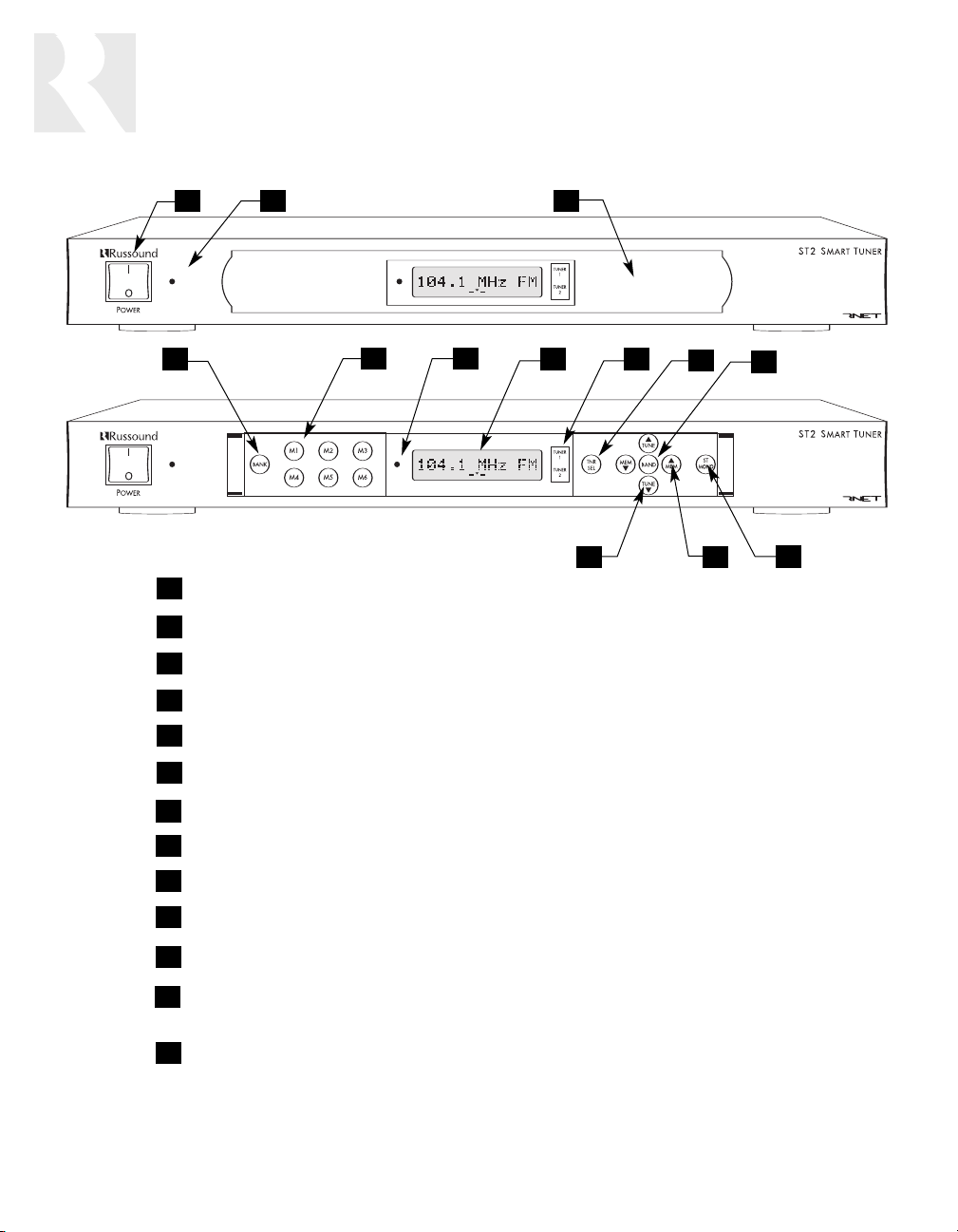
ST2 FRONT PANEL
1
4
1
MAIN POWER SWITCH - Turns power on and off
2
POWER ON/OFF LED - Indicates power on or off
3
REMOVABLE COVER LENS - Covers the selection buttons on the tuner
4
BANK SELECT BUTTON - Selects bank 1-6
5
MEMORY SELECT BUTTONS - Sets and selects memory presets 1-6 for each bank
2
5
6
3
7
13
8
9
12
10
11
6
IR RECEIVER - Receives IR signal from remote control
7
LCD PANEL - 12-character backlit display shows station, custom names, etc.
8
TUNER 1/TUNER 2 - Backlit tuner selection indicator
9
TNR SEL - Selects Tuner 1 or Tuner 2, and accesses tuner setup menus
10
BAND - Selects AM or FM band, enters menu selections when programming
11
ST/MONO - Selects stereo or mono mode for AM/FM, and Distant/Local reception
12
MEM PRESET UP/DOWN - Selects memory presets starting with last preset, and toggles through
menu features
13
TUNE UP/DOWN - Manually selects radio stations, toggles through menu settings
6
RS-232
INTERFACE
IR
LR
A
UDIO OUTPUT
12VDC 1.5A
I
NOUT
NEWMARKET, NH U.S.A.
ST2
Smart Tuner
LINK
K
EYPAD PORTS
T
UNER
1T
UNER
2
FM C
OAX
L
OOP
A
NTENNA
FM C
OAX
L
OOP
A
NTENNA
Serial#
MADE IN KOREA
IR
L
R
A
UDIO OUTPUT
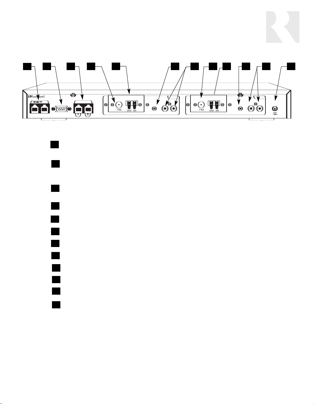
COMPONENT GUIDE
ST2 REAR PANEL
1
2 8
3 124 5
TUNER 2
1
RNET LINK IN/LINK OUT - Links to other Russound components that are RNET compatible, dis-
6 7 10 11
9
TUNER 1
plays frequency and other information on the UNO keypads
2
RS-232 INTERFACE - The RS-232 Interface allows the tuner to be controlled by PC or other devices
that have an RS-232 Interface. The RS-232 Interface also allows for firmware updates and programming (DB9 Cable)
3
KEYPAD PORTS - RJ-45 Keypad ports for ST2-KP tuner keypads in dedicated, non-RNET systems (Do not connect UNO keypads to these ports)
4
FM COAX - FM Antenna threaded F-connection (75 ohms)
5
LOOP ANTENNA - AM antenna connection (300 ohms)
6
IR INPUT - IR control input (direct IR control per tuner)
7
AUDIO OUTPUT - Line level audio signal outputs (RCA Cable)
8
FM COAX - FM Antenna threaded F-connection (75 ohms)
9
LOOP ANTENNA - AM antenna connection (300 ohms)
10
IR INPUT - IR control input (direct IR control per tuner)
11
AUDIO OUTPUT - Line level audio signal outputs (RCA Cable)
12
POWER SUPPLY - 12VDC external power supply connection
7
TUNE
TUNE
FAV 1
SEEK
ST/
MONO
LOC/
DX
SEEK
TUNE
TUNER 1 TUNER 2
4
MEM
BAN
K
123
56
789
0
PWR
MEM
TUNE
AM/FM
FAV 2
OK
COMPONENT GUIDE
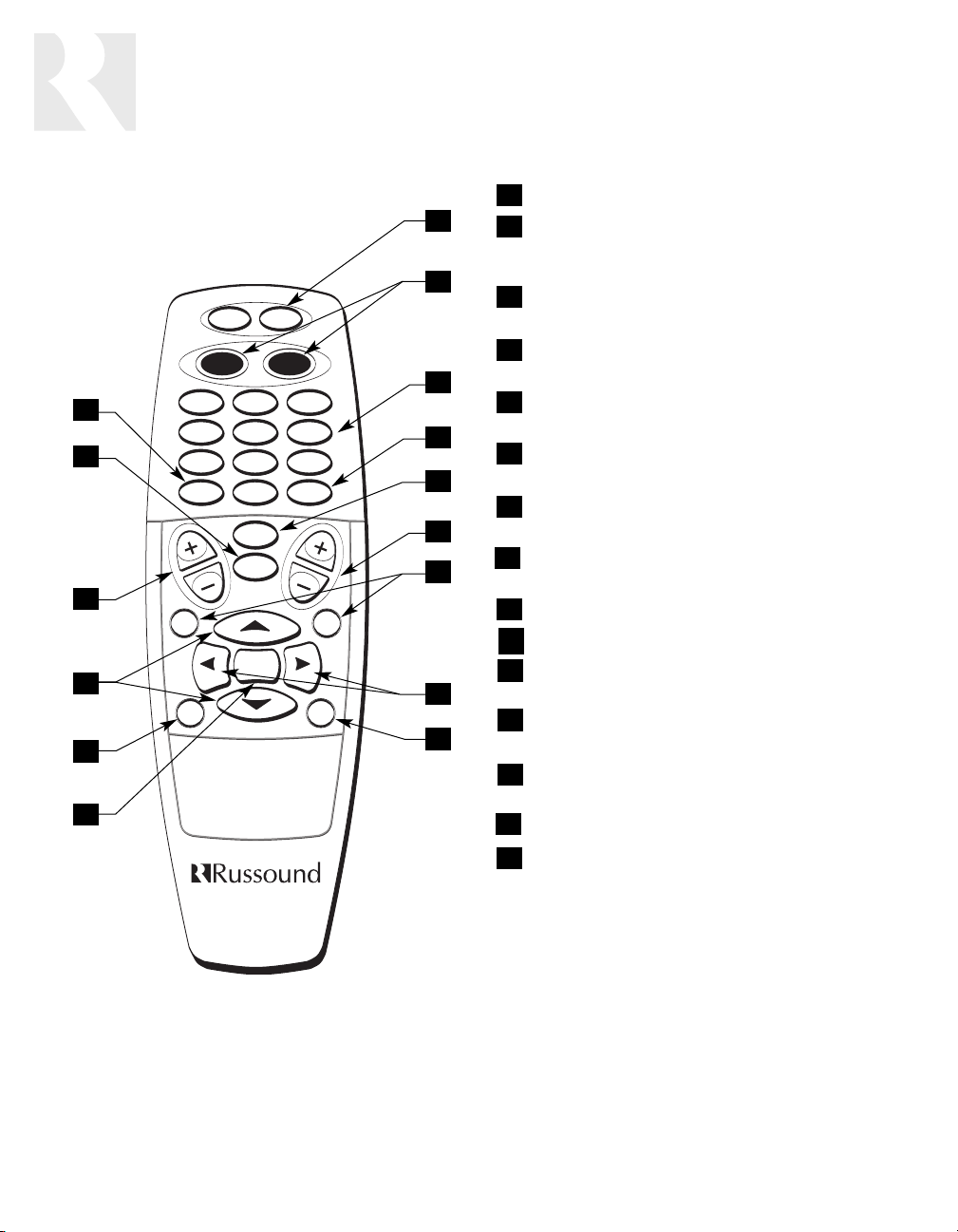
ST2-RC REMOTE CONTROL
15
14
13
12
11
10
1
POWER - Puts the tuner in/out of standby mode
1
2
TUNER CONTROL - Select Tuner 1 or
Tuner 2 and all subsequent button presses affect
2
that tuner
3
NUMERIC INPUT - Number buttons for direct
selection of station, bank, preset
4
BANK SELECT - Used for direct bank selection
3
4
5
6
7
8
9
(numeric input 1-6)
5
TUNE SELECT - Used for direct station selec-
tion (numeric input)
6
TUNE UP/DOWN - Incrementally scrolls through
station numbers
7
FAV 1/FAV 2 - Sets/Selects Favorite 1 or 2
preset selection on ST2 tuner
8
SEEK UP/DOWN - Seeks the next tuned station
up/down
9
LOCAL/DISTANCE - Optimizes station reception
10
OK - Confirms direct entries
11
STEREO/MONO - Selects stereo or mono
broadcast
12
TUNE UP/DOWN - Scrolls through station
numbers
13
MEM UP/DOWN - Scrolls through preset sta-
tions within selected bank
14
AM/FM - Selects AM or FM band
15
MEM SELECT - Used for direct memory select
(numeric input 1-6)
8
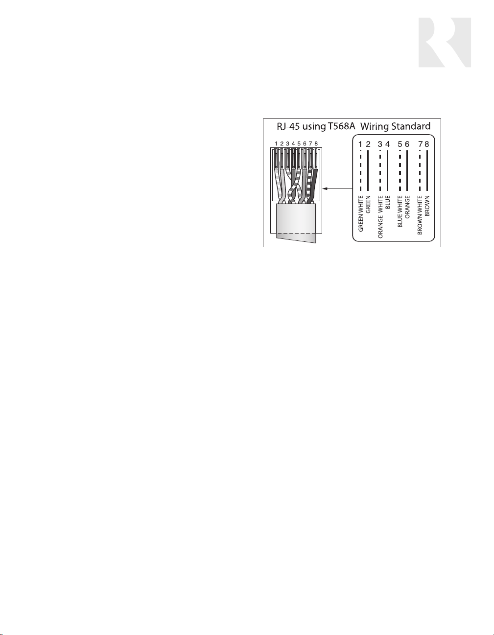
Power
ST2-KP RJ-45 Connection Wiring
To power the tuner, connect the 12VDC external
power supply by inserting the power supply jack
into the power supply connection on the tuner’s
rear panel.
Audio Output
Connect one end of a dual RCA audio cable to
the Tuner 1 Audio Output connection. Keep proper channel identity. Attach the other end of the
RCA cables to the source input of the audio control system. Repeat the same procedure for the
Tuner 2 Audio Output.
IR Connections
The ST2 Tuner can be controlled by infrared
commands received through the two IR connections on the rear panel. The ST2 Tuner component contains two tuners, which must be set up
as two sources. There are two IR connections one for each tuner in the ST2. You will need two
IR link cables (Russound P/N 09-0508) for these
connections. There is a unique IR code set each
for Tuner 1 and Tuner 2, which allow each to be
controlled independently. These codes can be
learned from the ST2-RC remote into learningcapable remotes and keypads. If you are using
an IR-controlled system from another manufacturer, installation should be similar. The ST2 IR
codes may be learned into many other manufacturers’ remote controls that have learning capability for unified control over the A/V equipment.
RNET Connection
o link the ST2 to an RNET-compatible device,
T
-5 passthr
use a CA
lar wiring terminations at each end. Connect one
end of the cable to the RNET Link In of the ST2
tuner
cable to the RNET Link Out connection on the
RNET-compatible device.
T
, and connect the other end of the patch
ough patch cable with simi-
ST2 SETUP AND CONNECTIONS
BASIC CONNECTIONS
ST2-KP Keypad to ST2 Connection
(Non-RNET System)
The ST2-KP connects to the ST2 tuner with
CAT-5 cable, using an RJ-45 (T568A) jack on the
tuner connection end of the cable. Be sure to
use the keypad ports for the ST2-KP and NOT
the RNET link ports. The ST2 tuner provides
connections for up to two ST2-KP keypads. An
SA-ZX3 Keypad Splitter can be used to add additional keypads.
Note: ST2-KP keypads are designed for use
with IR-controlled systems (non-RNET systems).
When the ST2 Tuner is a component of an RNET
system such as CAV6.6, the RNET-system UNOS2 keypads are used
Rack Mount Installation
The ST2 can be mounted in a standard component rack using the rack ears provided. Line up
the rack ear’s two rows of screw holes with the
ew holes on the side of the tuner
ee scr
thr
ovided to secur
ews pr
the scr
onto the unit on both sides. The ST2 tuner
should not be installed above a high heat-pr
ducing component such as a power amplifier
e the rack ears
. Use
-
o
.
9
 Loading...