


DTR-8.8
Table of contents
 Loading...
DTR-8.8
Instruction Manual
AV Receiver
2
Important Safety Instructions
1. Read these instructions.
2. Keep these instructions.
3. Heed all warnings.
4. Follow all instructions.
5. Do not use this apparatus near water.
6. Clean only with dry cloth.
7. Do not block any ventilation openings. Install in
accordance with the manufacturer’s instructions.
8. Do not install near any heat sources such as radia-
tors, heat registers, stoves, or other apparatus
(including amplifiers) that produce heat.
9. Do not defeat the safety purpose of the polarized or
grounding-type plug. A polarized plug has two
blades with one wider than the other. A grounding
type plug has two blades and a third grounding
prong. The wide blade or the third prong are pro-
vided for your safety. If the provided plug does not
fit into your outlet, consult an electrician for
replacement of the obsolete outlet.
10. Protect the power cord from being walked on or
pinched particularly at plugs, convenience recepta-
cles, and the point where they exit from the appara-
tus.
11. Only use attachments/accessories specified by the
manufacturer.
12.
Use only with the cart, stand,
tripod, bracket, or table spec-
ified by the manufacturer, or
sold with the apparatus.
When a cart is used, use cau-
tion when moving the cart/
apparatus combination to
avoid injury from tip-over.
13. Unplug this apparatus during lightning storms or
when unused for long periods of time.
14. Refer all servicing to qualified service personnel.
Servicing is required when the apparatus has been
damaged in any way, such as power-supply cord or
plug is damaged, liquid has been spilled or objects
have fallen into the apparatus, the apparatus has
been exposed to rain or moisture, does not operate
normally, or has been dropped.
15. Damage Requiring Service
Unplug the apparatus from the wall outlet and refer
servicing to qualified service personnel under the
following conditions:
A. When the power-supply cord or plug is damaged,
B. If liquid has been spilled, or objects have fallen
into the apparatus,
C. If the apparatus has been exposed to rain or
water,
D. If the apparatus does not operate normally by
following the operating instructions. Adjust only
those controls that are covered by the operating
instructions as an improper adjustment of other
controls may result in damage and will often
require extensive work by a qualified technician
to restore the apparatus to its normal operation,
E. If the apparatus has been dropped or damaged in
any way, and
F. When the apparatus exhibits a distinct change in
performance this indicates a need for service.
16. Object and Liquid Entry
Never push objects of any kind into the apparatus
through openings as they may touch dangerous volt-
age points or short-out parts that could result in a
fire or electric shock.
The apparatus shall not be exposed to dripping or
splashing and no objects filled with liquids, such as
vases shall be placed on the apparatus.
Don’t put candles or other burning objects on top of
this unit.
17. Batteries
Always consider the environmental issues and fol-
low local regulations when disposing of batteries.
18. If you install the apparatus in a built-in installation,
such as a bookcase or rack, ensure that there is ade-
quate ventilation.
Leave 20 cm (8") of free space at the top and sides
and 10 cm (4") at the rear. The rear edge of the shelf
or board above the apparatus shall be set 10 cm (4")
away from the rear panel or wall, creating a flue-like
gap for warm air to escape.
WARNING:
TO REDUCE THE RISK OF FIRE OR ELECTRIC
SHOCK, DO NOT EXPOSE THIS APPARATUS
TO RAIN OR MOISTURE.
CAUTION:
TO REDUCE THE RISK OF ELECTRIC SHOCK,
DO NOT REMOVE COVER (OR BACK). NO
USER-SERVICEABLE PARTS INSIDE. REFER
SERVICING TO QUALIFIED SERVICE
PERSONNEL.
The lightning flash with arrowhead symbol, within an
equilateral triangle, is intended to alert the user to the
presence of uninsulated “dangerous voltage” within
the product’s enclosure that may be of sufficient
magnitude to constitute a risk of electric shock to
persons.
The exclamation point within an equilateral triangle is
intended to alert the user to the presence of important
operating and maintenance (servicing) instructions in
the literature accompanying the appliance.
WARNING
RISK OF ELECTRIC SHOCK
DO NOT OPEN
RISQUE DE CHOC ELECTRIQUE
NE PAS
OUVRIR
AVIS
PORTABLE CART WARNING
S3125A
Thank you for purchasing an Integra AV Receiver. Please read this manual thoroughly before making
connections and plugging in the unit. Following the instructions in this manual will enable you to
obtain optimum performance and listening enjoyment from your new AV Receiver.
Please retain this manual for future reference.

3
Precautions
1. Recording Copyright
—Unless it’s for personal use
only, recording copyrighted material is illegal with-
out the permission of the copyright holder.
2. AC Fuse
—The AC fuse inside the unit is not user-
serviceable. If you cannot turn on the unit, contact
the dealer from whom you purchased this unit.
3. Care
—Occasionally you should dust the unit all
over with a soft cloth. For stubborn stains, use a soft
cloth dampened with a weak solution of mild deter-
gent and water. Dry the unit immediately afterwards
with a clean cloth. Don’t use abrasive cloths, thin-
ners, alcohol, or other chemical solvents, because
they may damage the finish or remove the panel let-
tering.
4. Power
WARNING
BEFORE PLUGGING IN THE UNIT FOR THE
FIRST TIME, READ THE FOLLOWING SEC-
TION CAREFULLY.
AC outlet voltages vary from country to country.
Make sure that the voltage in your area meets the
voltage requirements printed on the unit’s rear panel
(e.g., AC 230 V, 50 Hz or AC 120 V, 60 Hz).
The power cord plug is used to disconnect this unit
from the AC power source. Make sure that the plug
is readily operable (easily accessible) at all times.
Pressing the [Standby/On] button to select Standby
mode does not fully shutdown the unit. If you do not
intend to use the unit for an extended period,
remove the power cord from the AC outlet.
5. Never Touch this Unit with Wet Hands
—Never
handle this unit or its power cord while your hands
are wet or damp. If water or any other liquid gets
inside this unit, have it checked by the dealer from
whom you purchased this unit.
6. Handling Notes
• If you need to transport this unit, use the original
packaging to pack it how it was when you origi-
nally bought it.
• Do not leave rubber or plastic items on this unit
for a long time, because they may leave marks on
the case.
• This unit’s top and rear panels may get warm
after prolonged use. This is normal.
• If you do not use this unit for a long time, it may
not work properly the next time you turn it on, so
be sure to use it occasionally.
For U.S. models
FCC Information for User
CAUTION:
The user changes or modifications not expressly
approved by the party responsible for compliance could
void the user’s authority to operate the equipment.
NOTE:
This equipment has been tested and found to comply
with the limits for a Class B digital device, pursuant to
Part 15 of the FCC Rules. These limits are designed to
provide reasonable protection against harmful interfer-
ence in a residential installation.
This equipment generates, uses and can radiate radio
frequency energy and, if not installed and used in accor-
dance with the instructions, may cause harmful interfer-
ence to radio communications. However, there is no
guarantee that interference will not occur in a particular
installation. If this equipment does cause harmful inter-
ference to radio or television reception, which can be
determined by turning the equipment off and on, the
user is encouraged to try to correct the interference by
one or more of the following measures:
• Reorient or relocate the receiving antenna.
• Increase the separation between the equipment and
receiver.
• Connect the equipment into an outlet on a circuit dif-
ferent from that to which the receiver is connected.
• Consult the dealer or an experienced radio/TV techni-
cian for help.
For Canadian Models
NOTE:
THIS CLASS B DIGITAL APPARATUS
COMPLIES WITH CANADIAN ICES-003.
For models having a power cord with a polarized plug:
CAUTION:
TO PREVENT ELECTRIC SHOCK,
MATCH WIDE BLADE OF PLUG TO WIDE SLOT,
FULLY INSERT.
Modèle pour les Canadien
REMARQUE:
CET APPAREIL NUMÉRIQUE DE
LA CLASSE B EST CONFORME À LA NORME
NMB-003 DU CANADA.
Sur les modèles dont la fiche est polarisée:
ATTENTION:
POUR ÉVITER LES CHOCS ÉLEC-
TRIQUES, INTRODUIRE LA LAME LA PLUS
LARGE DE LA FICHE DANS LA BORNE CORRE-
SPONDANTE DE LA PRISE ET POUSSER
JUSQU’AU FOND.

4
Contents
Features ............................................................ 6
Supplied Accessories ...................................... 7
Multiroom Capability ........................................ 8
Getting to Know the AV Receiver ................... 9
Front Panel .............................................................. 9
Display .................................................................. 11
Rear Panel ............................................................. 12
Remote Controller .......................................... 15
Installing the Batteries .......................................... 15
Using the Remote Controller ................................ 15
About the Remote Controller Modes .................... 16
Receiver/Tape Mode ............................................. 16
DVD Mode ........................................................... 18
CD/MD/CDR Modes ............................................ 19
Dock Mode ........................................................... 20
Net/USB Mode ..................................................... 21
Connecting Your Speakers ........................... 22
Enjoying Home Theater ........................................ 22
Connecting Your Speakers ................................... 23
Bi-amping the Front Speakers .............................. 25
Bridging the Front Speakers ................................. 26
Connecting Antennas .................................... 27
Connecting the Indoor FM Antenna ..................... 27
Connecting the AM Loop Antenna ...................... 27
Connecting an Outdoor FM Antenna ................... 28
Connecting an Outdoor AM Antenna ................... 28
Connecting Your Components ..................... 29
About AV Connections ........................................ 29
Connecting Audio and Video Signals to
the AVReceiver .................................................. 30
Which Connections Should I Use? ....................... 30
Connecting a TV or Projector ............................... 32
Connecting a DVD player .................................... 33
Connecting a VCR or DVR for Playback ............. 35
Connecting a VCR or DVR for Recording ........... 36
Connecting a Satellite, Cable, or Terrestrial
Set-top box or Other Video Source .................... 37
Connecting Components with HDMI ................... 38
Connecting a Game Console ................................ 40
Connecting a Camcorder or Other AV
Component ......................................................... 41
Connecting a CD Player ....................................... 42
Connecting a Turntable ........................................ 42
Connecting a Cassette, CDR, MiniDisc,
or DAT Recorder ................................................ 43
Connecting a Power Amplifier ............................. 43
Connecting an RI Dock ........................................ 44
Connecting the Power Cords of Other
Components (North American model only) ....... 44
Connecting an External Controller ....................... 44
Connecting Integra/Onkyo Components ....... 45
Connecting the Power Cord .................................. 45
Turning On the AV Receiver ......................... 46
Turning On and Standby ....................................... 46
First Time Setup ............................................. 47
Speaker Settings .................................................... 47
HDMI Monitor Setup ............................................ 48
HDMI Input Setup ................................................50
Component Video Input Setup .............................. 51
Changing the Input Display ..................................52
Digital Input Setup ................................................ 52
Analog Input Setup ...............................................53
Picture Quality Menu ............................................ 54
Automatic Speaker Setup
(Audyssey MultEQ XT) .....................................55
TV Format Setup
(not North American models) ............................. 60
AM Frequency Step Setup (on some models) ......61
Playing Your AV Components ...................... 62
Basic AV Receiver Operation ............................... 62
Listening to the Radio .................................... 63
Listening to AM/FM Stations ............................... 63
Using RDS (not North American model) .............65
Listening to HD Radio™ Stations
(North American model only) ............................67
Listening to XM Satellite Radio
®
(North American Model Only) ...........................69
Listening to SIRIUS Satellite Radio
®
(North American Models Only) .........................74
Presetting AM, FM, XM, and SIRIUS Stations .... 82
Common Functions ........................................ 83
Setting the Display Brightness .............................. 83
Adjusting Speaker Levels .....................................83
Muting the AV Receiver ....................................... 83
Using the Sleep Timer ..........................................84
Using Headphones ................................................84
Displaying Source Information .............................84
Selecting Audio Inputs .......................................... 85
Specifying the Digital Signal Format ...................85
Using the Re-EQ Function .................................... 86
Using the Late Night Function .............................. 86
Tone Control Settings ...........................................87
Using the Listening Modes ............................ 88
Selecting the Listening Modes .............................. 88
Listening Modes Available for Each
Source Format ....................................................89
About the Listening Modes ................................... 93
Recording ........................................................ 95
Recording the Input Source ..................................95
Recording from Different AV Sources ................. 95
Onscreen Setup Menus ................................. 96
Menu Map ............................................................. 96
Adjusting the Listening Modes .....................97
Audio Adjust ......................................................... 97
Listening Mode Presets ......................................... 99

5
Contents
—Continued
Advanced Setup ...........................................101
Speaker Setup ...................................................... 101
Source Setup ........................................................108
Miscellaneous Setup ............................................111
Hardware Setup ...................................................113
Lock Setup ..........................................................115
Net/USB ......................................................... 116
About Net/USB ................................................... 116
Connecting the AV Receiver ..............................117
Playing Music Files on a Server ..........................118
Windows Media
®
Player 11 Setup .....................119
Playing Music Files on a USB Device ................119
Listening to Internet Radio ..................................121
Network Settings .................................................122
Zone 2 and Zone 3 ........................................ 124
Connecting Zone 2 .............................................. 124
Connecting Zone 3 .............................................. 125
Powered Zone 2 Setting ......................................126
Zone 2/Zone 3 Out Settings ................................127
Using Zone 2 and Zone 3 ....................................127
Using the 12V Triggers .......................................130
Using the Remote Controller in Zone 2/3 and
Multiroom Control Kits ....................................131
Controlling Other Components ................... 132
Entering Remote Control Codes .........................132
Resetting the Remote Controller .........................133
Learning Commands ........................................... 135
Using Macros ......................................................136
Troubleshooting ........................................... 137
Specifications ............................................... 141
If you can’t resolve an issue, try resetting the AV
receiver by holding down the [VCR/DVR] button
and pressing the [Standby/On] button.
6
Features
Amplifier
• 7-channel amplifier
• 140 watts minimum continuous power per channel, 8
ohm loads, 2 channels driven from 20 Hz to 20 kHz,
with a maximum total harmonic distortion of 0.05%
(FTC)
• Linear Optimum Gain Volume Circuitry
•Powered Zone 2 capability
• Bi-amp and bridging capability for front speakers
• WRAT (Wide Range Amplifier Technology)
• VLSC
*1
(Vector Linear Shaping Circuitry) on all
channels
• Massive High Current Power Supply (H.C.P.S.) trans-
former
Processing
• THX
*1
Surround EX
• THX Ultra2
*2
certified
• Dolby
*3
Digital, Dolby Digital EX, Dolby Digital
Plus, Dolby TrueHD, Dolby Pro Logic IIx
• DTS
*4
, DTS-ES Discrete, DTS-ES Matrix, DTS-HD
Master Audio, DTS-HD High Resolution, DTS 96/24,
DTS Neo:6
• Neural Surround
*5
, THX-Neural
• Theater-Dimensional
*6
virtual surround sound
• DSD Direct
• 192 kHz/24-bit D/A converters
•Powerful and highly accurate 32-bit DSP processing
• Re-EQ
*7
function
•Tone control on all channels (7.1)
• 15-band EQ on 7 channels, 5-band EQ on subwoofer
Audio/Video
• Zone 2 with level, tone, balance, and left, right, and
subwoofer pre outs, and composite video output, and
component video output (assignable).
• Zone 3 with level, balance, and left, right, and sub-
woofer pre outs
•4 HDMI
*8
inputs, 2 outputs (Version 1.3a)
• HDMI upconversion of composite video, S-Video,
and component sources (720p, 1080i, 1080p capable)
• Component video upconversion of composite video
and S-Video sources
• Composite video to S-Video and S-Video to compos-
ite video conversion
•6 digital inputs (3 optical, 3 coaxial), 1 output (optical)
•3 component video inputs, 2 outputs
•6 S-Video inputs, 2 outputs
• RS-232 control
• Color-coded, assignable 7.1 multichannel input
• 7.1-channel pre out
Tuner
•XM
*9
Satellite Radio ready (N. America only)
* XM Mini-Tuner and Home Dock required; sold separately.
• SIRIUS
*10
Satellite Radio ready (N. America only)
* SiriusConnect Home tuner kit required; sold separately.
• HD Radio
*11
reception (N. America only)
• 40 AM/FM/SIRIUS/XM presets (N. American model)
• 40 AM/FM presets (other models)
• AM/FM auto tuning
• RDS radio data
• Direct tuning
Others
• Network-ready for playing music files on a networked
computer or media server, or for listening to Internet
radio
• USB port for playing music files on USB mass storage
devices (e.g., USB flash drives and MP3 players)
• Supports MP3, WMA, WAV, and M4A file formats
• Audyssey MultEQ XT room correction
*12
• Easy-to-use onscreen setup menus
• IR IN A/B and OUT
• 12V TRIGGER OUT A, B, C
• Preprogrammed remote controller for use with other
AV components, with Learning and Macro functions
*1
VLSC and the VLSC logo are registered trademarks of Onkyo
Corporation.
*2
THX and Ultra2 are trademarks of THX Ltd. THX may be reg-
istered in some jurisdictions. All rights reserved. Surround EX
is a trademark of Dolby Laboratories. Used with permission.
*3
Manufactured under license from Dolby Laboratories.
“Dolby”, “Pro Logic” and the double-D symbol are trademarks
of Dolby Laboratories.
*4
“DTS” is a registered trademark of DTS, Inc., and “DTS-HD
Master Audio” is a trademark of DTS, Inc.
*5
Neural Surround is a trademark owned by Neural Audio Cor-
poration, THX is a trademark of THX Ltd., which may be reg-
istered in some jurisdictions. All rights reserved.
*6
Theater-Dimensional is a trademark of Onkyo Corporation.
*7 Re-Equalization and the “Re-EQ” logo are trademarks of THX
Ltd.
*8
HDMI, the HDMI logo and High Definition Multimedia Inter-
face are trademarks or registered trademarks of HDMI Licens-
ing, LLC.
7
Features
—Continued
*9
XM Ready
®
is a trademark of XM Satellite Radio Inc. ©2005
XM Satellite Radio Inc. All rights reserved.
*10
©2005 SIRIUS Satellite Radio Inc. “SIRIUS,” SiriusConnect,
the SIRIUS dog logo, channel names and logos are trademarks
of SIRIUS Satellite Radio Inc. Available only in the contiguous
United States (excluding Alaska and Hawaii) and Canada.
*11
HD Radio
™
Technology Manufactured Under License From
iBiquity Digital Corporation. “iBiquity Digital” and the “HD
Radio” and “HD” Symbols are registered trademarks of iBiq-
uity Digital Corporation. “HD Radio” is a trademark of iBiq-
uity Digital Corporation. U.S. and Foreign Patents.
*12
Manufactured under license from Audyssey Laboratories. U.S.
and foreign patents pending. Audyssey MultEQ XT is a trade-
mark of Audyssey Laboratories.
* AMD is a trademark of Advanced Micro Devices, Inc.
* Apple and iPod are trademarks of Apple Computer, Inc., regis-
tered in the U.S. and other countries.
* Intel and Pentium are registered trademarks of Intel Corpora-
tion.
* Microsoft, Windows, Windows Mobile, Windows Media,
ActiveSync, DirectX, and Internet Explorer are either regis-
tered trademarks or trademarks of Microsoft Corporation in the
United States and/or other countries.
* Microsoft product screen shot(s) reprinted with permission
from Microsoft Corporation.
* “Niles” is a registered trademark of Niles Audio Corporation.
* “Xantech” is a registered trademark of Xantech Corporation.
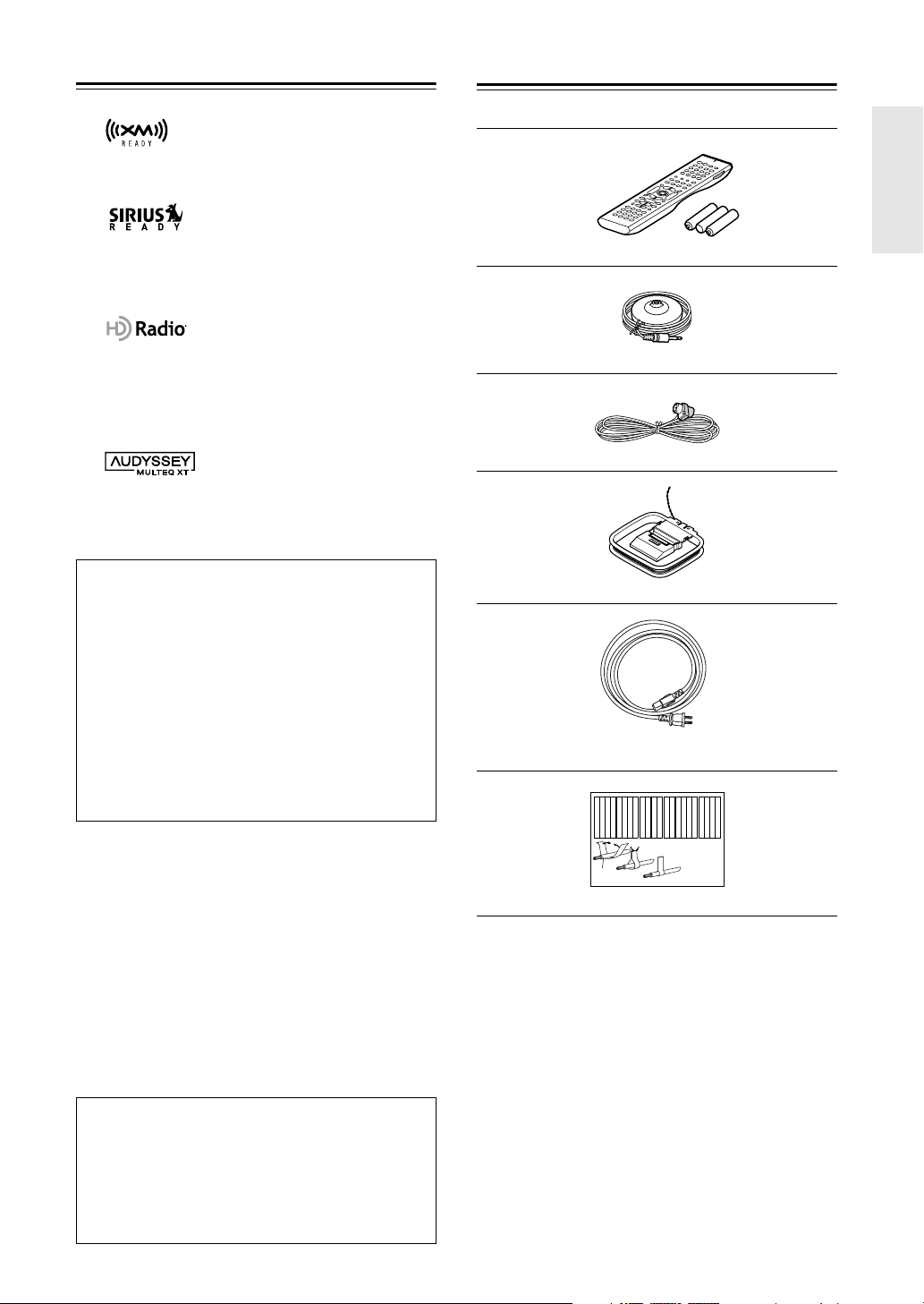
Supplied Accessories
Make sure you have the following accessories:
* In catalogs and on packaging, the letter at the end of the product
name indicates the color. Specifications and operation are the same
regardless of color.
THX Ultra2
Before any home theater component can be THX Ultra2
certified, it must pass a rigorous series of quality and per-
formance tests. Only then can a product feature the THX
Ultra2 logo, which is your guarantee that the Home The-
ater products you purchase will give you superb perfor-
mance for many years to come. THX Ultra2 requirements
define hundreds of parameters, including power amplifier
performance, and pre-amplifier performance and opera-
tion for both digital and analog domains. THX Ultra2
receivers also feature proprietary THX technologies (e.g.,
THX Mode) which accurately translate movie
soundtracks for home theater playback.
This product incorporates copyright protection technol-
ogy that is protected by U.S. patents and other intellectual
property rights. Use of this copyright protection technol-
ogy must be authorized by Macrovision Corporation, and
is intended for home and other limited consumer uses
only unless otherwise authorized by Macrovision.
Reverse engineering or disassembly is prohibited.
Remote controller and three batteries (AA/R6)
Speaker setup microphone
Indoor FM antenna
AM loop antenna
Power cord
(Power cord varies from country to country.)
Speaker cable labels
Front
Left
Front
Left
SP-B
/
Zone 2
Left
SP-B
/
Zone 2
Left
Surround
Right
Surround
Right
Surround Back
Right
Surround Back
Right
Zone 2
Right
Zone 2
Right
Front
Left
Front
Left
SP-B
/
Zone 2
Left
SP-B
/
Zone 2
Left
Front
Right
Front
Right
SP-B
/
Zone 2
Right
SP-B
/
Zone 2
Right
Front
Right
Front
Right
SP-B
/
Zone 2
Right
SP-B
/
Zone 2
Right
Surround
Right
Surround
Right
Center
Center
Center
Center
Surround
Left
Surround
Left
Surround
Left
Surround
Left
Surround Back
Right
Surround Back
Right
Zone 2
Right
Zone 2
Right
Surround Back
Left
Surround Back
Left
Zone 2
Left
Zone 2
Left
Surround Back
Left
Surround Back
Left
Zone 2
Left
Zone 2
Left
1
2
3
Speaker Cable
8
Multiroom Capability
You can use three speaker systems with this AV receiver
—a surround-sound speaker system (up to 7.1 channels) in
your main listening room, a stereo speaker system in a second room, or Zone 2, as we call it, and another stereo
speaker system in a third room that we call Zone 3. And, you can select a different audio source for each room.
Main Room:
In your main listening room, you can enjoy up to 7.1-channel playback (see pages 22–26).
You can enjoy the various listening modes such as Dolby, DTS, and THX (see pages 88–94).
*While Powered Zone 2 is being used, playback is reduced to 5.1-channels (see page 124).
Zone 2:
In your Zone 2 room, you can enjoy 2-channel stereo playback and video playback (see page 124).
*The listening modes cannot be used with Zone 2 and Zone 3.
Zone 3:
In your Zone 3 room, you can enjoy 2-channel stereo playback (see page 125).
*The listening modes cannot be used with Zone 2 and Zone 3.
*External power amplifier required.
Main Room
Front left and right speakers
Center speaker
Surround left and right speakers
Subwoofer
Zone 2 Room
Left and right
stereo speakers
Zone 3 Room
Left and right
stereo speakers
Surround back left and right
speakers
*While Powered Zone 2 is being
used, nothing is output by these
speakers (page 126).
9
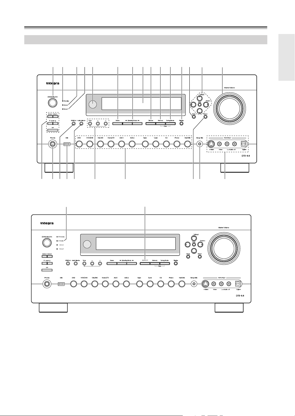
Getting to Know the AV Receiver
The actual front panel has various logos printed on it. They are not shown here for clarity.
The page numbers in parentheses show where you can find the main explanation for each item.
A
Standby/On button (46)
Sets the AV receiver to On or Standby.
B
Standby indicator (46)
Lights up when the AV receiver is on Standby and
flashes while a signal is being received from the
remote controller.
C
Ready indicator (114)
North American model doesn’t have this indicator.
Lights up when the AV receiver is on Standby and
HDMI Power Control is enabled.
D
Zone 2 indicator (128)
Flashes when Zone 2 is being set. Lights up when
Zone 2 is on.
Front Panel
PO
6 97 8 J K L MN1 2
ZYRQ
54
UTS W
X
V
J
3
North American model
Other models

10
Getting to Know the AV Receiver
—Continued
E
Zone 3 indicator (128)
Flashes when Zone 3 is being set. Lights up when
Zone 3 is on.
F
Remote-control sensor (15)
Receives control signals from the remote controller.
G
Stereo button (88)
Selects the Stereo listening mode.
H
Listening Mode [ ]/[ ] buttons (88)
Select the listening modes.
I
Display
See “Display” on page 11.
J
Dimmer (RT/PTY/TP) button (66, 83)
Adjusts the display brightness.
On models other than the North American model,
this is the RT/PTY/TP button, and it’s used with
RDS (Radio Data System). See “Using RDS (not
North American model)” on page 65.
K
Memory button (82)
Used when storing or deleting radio presets.
L
Tuning Mode button (63)
Selects the Auto or Manual tuning mode for AM
and FM radio.
M
Display button (84)
Displays various information about the currently
selected input source.
N
Setup button
Opens and closes the onscreen setup menus, which
are displayed on the connected TV.
O
Tuning, Preset, Arrow, and Enter buttons
When AM or FM is selected, the Tuning [ ] [ ]
buttons are used for radio tuning, and the Preset
[] [ ] buttons are used to select radio presets
(see page 82). With the onscreen setup menus, they
work as arrow buttons and are used to select and set
items. The Enter button is also used with the
onscreen setup menus.
P
Master Volume control (62)
Sets the volume of the AV receiver to –
∞
dB,
–81.5 dB, –81.0 dB through +18.0 dB (relative dis-
play).
The volume level can also be displayed as an abso-
lute value. See “Volume Setup” on page 111.
Q
Zone 2, Zone 3, Level [ ]/[ ], and Off
buttons (128, 129)
The Zone 2 button is used when setting Zone 2.
The Zone 3 button is used when setting Zone 3.
The Level Up and Down [ ]/[ ] buttons are used
when adjusting the volume level of Zone 2 or
Zone 3.
The Off button is used to turn off Zone 2 or Zone 3.
R
Phones jack (84)
This 1/4-inch phone jack is for connecting a stan-
dard pair of stereo headphones for private listening.
S
HDMI Out (49)
Used to set the HDMI Monitor setting.
T
USB port
A USB mass storage device, such as a USB flash
drive or MP3 player, containing music files (MP3,
WMA, WAV, M4A) can be plugged in here and the
music selected and played through the AV receiver.
U
Audio Selector button (85)
Selects the audio input: analog, digital, HDMI, or
multichannel.
V
Tone, Plus [+], and Minus [–] buttons (87,
129)
Used to adjust the tone (bass and treble), and the
volume and balance of Zone 2 and Zone 3.
W
Input selector buttons (62)
Select the following input sources: DVD,
VCR/DVR, CBL/SAT, Game/TV, AUX 1, AUX 2,
Tape, Tuner, CD, Phono, Net/USB.
X
Return button
Selects the previously displayed onscreen setup
menu.
Y
Setup Mic (55)
The automatic speaker setup microphone connects
here.
Z
AUX 2 Input (41, 95)
Used to connect a camcorder, game console, and so
on. There are input jacks for optical digital audio,
S-Video, composite video, and analog audio.
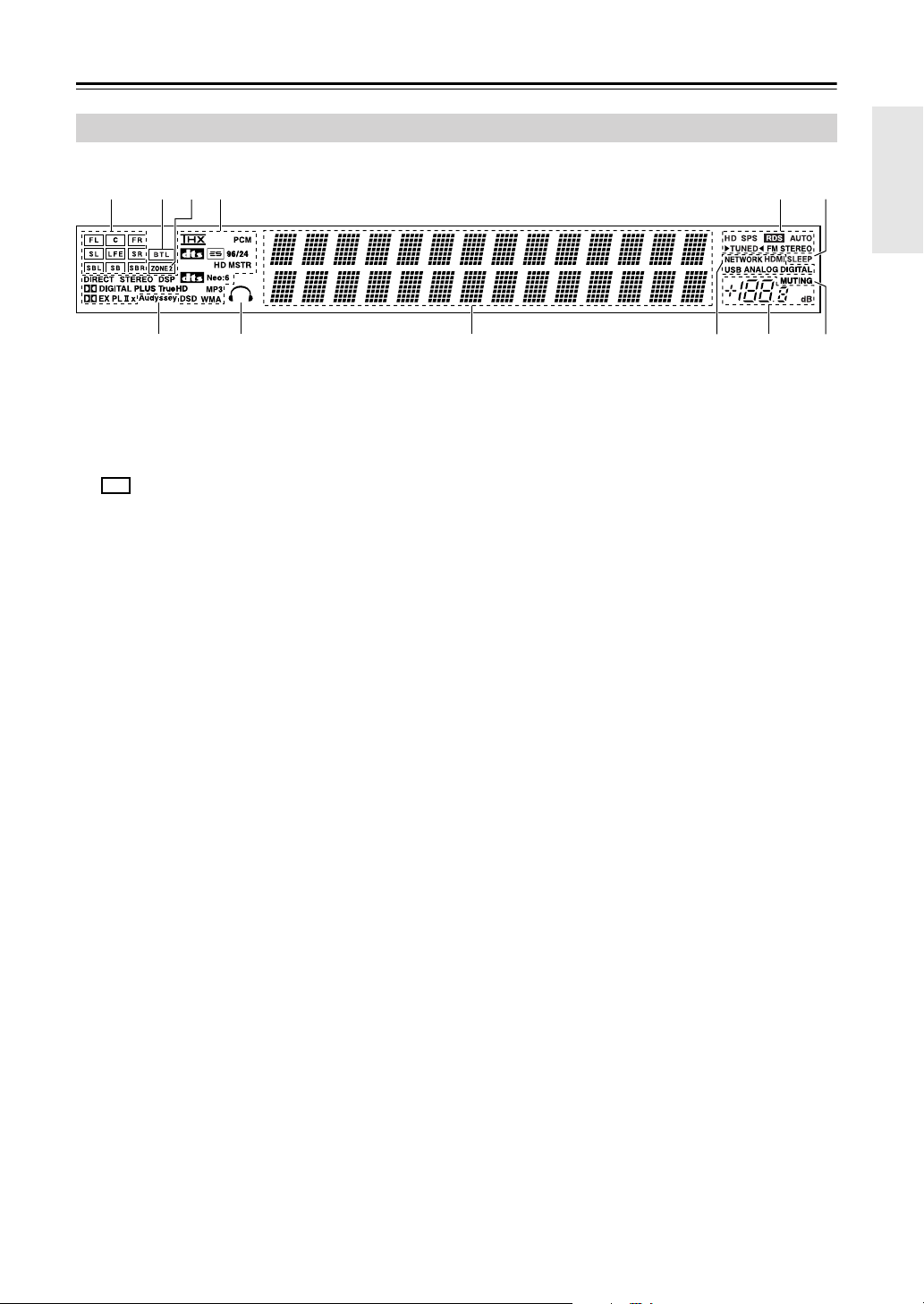
11
Getting to Know the AV Receiver
—Continued
For detailed information, see the pages in parentheses.
1
Speaker/channel indicators
Indicate the speaker configuration and channels
used by the current input source.
– : A box is displayed for each speaker that’s set
in the Speaker Configuration. No box appears for
speakers that are set to No or None.
The following abbreviations indicate which audio
channels are included in the current input signal.
–
FL
: Front left
–
C
: Center
–
FR
: Front right
–
SL
: Surround left
–
LFE
: Subwoofer (Low Frequency Effects)
–
SR
: Surround right
–
SBL
: Surround back left
–
SB
: Surround back
–
SBR
: Surround back right
2
BTL indicator (page 47)
Lights up when the Speaker Type setting is set to
BTL for bridged front speaker operation.
3
ZONE 2 indicator (page 128)
Lights up when Powered Zone 2 is being used.
4
Listening mode and format indicators (88)
Show the selected listening mode and audio input
signal format.
5
Tuning indicators (63)
HD (North American model only) (67):
Lights
up if the current AM or FM station supports HD
Radio technology.
SPS (North American model only) (68):
Lights up when tuned to a HD Radio station that’s
transmitting secondary multicast channels.
RDS (not North American model) (65):
Lights up when tuned to a radio station that supports
RDS (Radio Data System).
AUTO (63):
Lights up when Auto Tuning mode is
selected for AM or FM radio. Goes off when Man-
ual Tuning mode is selected.
TUNED (63):
Lights up when tuned to a radio sta-
tion.
FM STEREO (63):
Lights up when tuned to a ste-
reo FM station.
6
SLEEP indicator (84)
Lights up when the Sleep function has been set.
7
Audyssey indicator (55)
Lights up during automatic speaker setup.
8
Headphone indicator (84)
Lights up when a pair of headphones are plugged
into the PHONES jack.
9
Message area
Displays various information.
0
Audio input indicators (67, 85)
Indicate the type of audio input that’s selected as the
audio source: NETWORK, HDMI, USB, ANA-
LOG, or DIGITAL.
While a digital HD Radio transmission is being
received, the DIGITAL indicator lights up. While an
analog HD Radio transmission is being received,
the ANALOG indicator lights up.
A
Volume level (62)
Displays the volume level.
B
MUTING indicator (83)
Flashes while the AV receiver is muted.
Display
14 56
78 9 0AB
32
12
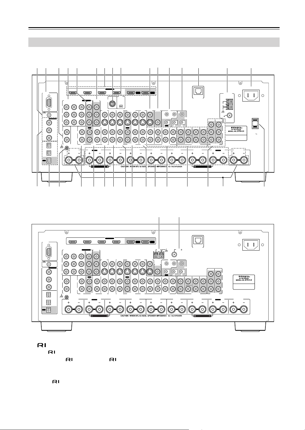
Getting to Know the AV Receiver
—Continued
A
REMOTE CONTROL
This (Remote Interactive) jack can be con-
nected to the jack on another -capable Inte-
gra/Onkyo component for remote and system
control.
To use , you must make an analog audio connec-
tion (RCA) between the AV receiver and the other
component, even if they are connected digitally.
B
RS232
This port is for connecting the AV receiver to home
automation equipment and external controllers.
C
PHONO IN
This audio input is for connecting a turntable.
Rear Panel
FRONT L
(BTL)
FRONT R
(BTL)
V
S
MONITOR
OUT
RS232
DIGITAL
COAXIAL
OPTICAL
REMOTE
CONTROL
IN 1
IN 1
IN 2
IN IN IN IN
PHONO
ZONE2 L
FRONT R FRONT LSURR R CENTER SURR L
SURR BACK R
CD TAPE AUX 1
GAME/TV
GAME/TV CBL/SAT
CBL/SAT
AUX 1 VCR/DVR
VCR/DVR DVD
DVD
GND
IN 2
IN 3
LL
RR
ASSIGNABLE
(DVD)
(CBL/SAT)
(VCR/DVR)
(GAME/TV)
(CD)
OUT
SIRIUS
XM
OUT
IN IN
OUT
IN IN FRONT FRONTCENTER
SUBWOOFER SUBWOOFER
CENTERSURR SURR
MULTI CH
PRE OUT
SURR BACK SURR BACK
AC OUTLET
AC INLET
AC 120V
SWITCHED
120W 1A MAX.
60Hz
Bi-AMP
SURR BACK L
Bi-AMP
ETHERNET
HDMI
IN 1IN 2IN 3IN 4
ASSIGNABLE
OUT
MAIN
OUT
SUB
ZONE2 R
COMPONENT VIDEO
ASSIGNABLE
IN 3
Y
CB/PB
CR/PR
IN 2 IN
1(DVD)
MONITOR
OUT 1
MONITOR OUT 2
/ZONE 2 OUT
V
S
ZONE 2
OUT
ZONE 2 ZONE 3
PRE OUT
L
R
SW
AM
ANTENNA
FM
75
HD RADIO
AB
IR
12V TRIGGER OUT
B
OUT
C
g
T U
8 9
64 5 J O21
R
QP
S
3 7
L
N
hVWX Za d e fbcY
North American model
Other models
FRONT L
(BTL)
FRONT R
(BTL)
V
S
MONITOR
OUT
ZONE 2
OUT
RS232
DIGITAL
COAXIAL
OPTICAL
REMOTE
CONTROL
IN 1
IN 1
IN 2
IN IN IN IN
PHONO
ZONE2 L
FRONT R FRONT LSURR R CENTER SURR L
SURR BACK R
CD TAPE AUX 1
GAME/TV
GAME/TV CBL/SAT
CBL/SAT
AUX 1 VCR/DVR
VCR/DVR DVD
DVD
GND
IN 2
IN 3
LL
RR
ASSIGNABLE
(DVD)
(CBL/SAT)
(VCR/DVR)
(GAME/TV)
(CD)
OUT
OUT
IN IN
OUT
IN IN FRONT FRONTCENTER
SUBWOOFER SUBWOOFER
CENTERSURR SURR
MULTI CH
PRE OUT
SURR BACK SURR BACK
AC INLET
Bi-AMP
SURR BACK L
Bi-AMP
ETHERNET
HDMI
IN 1IN 2IN 3IN 4
ASSIGNABLE
OUT
MAIN
OUT
SUB
ZONE2 R
AM
ANTENNA
FM75
COMPONENT VIDEO
ASSIGNABLE
IN 3
Y
CB/PB
CR/PR
IN 2 IN
1(DVD)
MONITOR
OUT 1
MONITOR OUT 2
/ZONE 2 OUT
V
S
ZONE 2 ZONE 3
PRE OUT
L
R
SW
AB
IR
12V TRIGGER OUT
B
OUT
C
K M

13
Getting to Know the AV Receiver
—Continued
D
COMPONENT VIDEO IN 1, 2, and 3
These RCA component video inputs are for con-
necting components with a component video output,
such as a DVD player, DVD recorder, or DVR (dig-
ital video recorder). They’re assignable, which
means you can assign each one to an input selector
to suit your setup. See “Component Video Input
Setup” on page 51.
E
COMPONENT VIDEO MONITOR OUT 1
This RCA component video output is for connect-
ing a TV or projector with a component video input.
F
COMPONENT VIDEO MONITOR OUT 2/
ZONE 2 OUT
This RCA component video output is for connect-
ing a TV or projector with a component video input
located in your main listening room or Zone 2.
G
HDMI IN 1–4, OUT MAIN, and OUT SUB
HDMI (High Definition Multimedia Interface) con-
nections carry digital audio and digital video.
The HDMI inputs are for connecting components
with an HDMI output, such as a DVD player, DVD
recorder, or DVR (digital video recorder). They’re
assignable, which means you can assign each one to
an input selector to suit your setup. See “HDMI
Input Setup” on page 50.
The HDMI outputs are for connecting a TV or pro-
jector with an HDMI input.
H
SIRIUS antenna (on North American model)
This jack is for connecting a SIRIUS digital
antenna, sold separately (see page 74).
I
XM antenna (on North American model)
This jack is for connecting an XM Mini-Tuner and
Home Dock, sold separately (see page 69).
J
MONITOR OUT
The S-Video or composite video jack should be
connected to a video input on your TV or projector.
K
AM ANTENNA (not North American model)
These push terminals are for connecting an AM
antenna.
L
ZONE 2 OUT
This composite video output can be connected to a
video input on a TV in Zone 2.
M
FM ANTENNA (not North American model)
This jack is for connecting an FM antenna.
N
IR IN A/B and OUT
A commercially available IR receiver can be con-
nected to the IR IN A or B jack, allowing you to
control the AV receiver while you’re in Zone 2, or
control it when it’s out of sight, for example,
installed in a cabinet.
A commercially available IR emitter can be con-
nected to the IR OUT jack to pass IR (infrared)
remote control signals through to other components.
O
12V TRIGGER OUT (A/B/C)
These outputs can be connected to the 12-volt trig-
ger inputs on other components.
P
ETHERNET
This port is for connecting the AV receiver to your
Ethernet network (e.g., router or switch) for playing
music files on a networked computer or media
server, or for listening to Internet radio.
Q
AM and FM ANTENNA (HD Radio) (on North
American model)
The AM push terminals are for connecting an AM
antenna. The FM jack is for connecting an FM
antenna.
R
AC INLET
The supplied power cord is connected here. The
other end of the power cord should be connected to
a suitable wall outlet.
S
DIGITAL COAXIAL IN 1, 2, and 3
These coaxial digital audio inputs are for connect-
ing components with a coaxial digital audio output,
such as a CD player or DVD player. They’re assign-
able, which means you can assign each one to an
input selector to suit your setup. See “Digital Input
Setup” on page 52.
T
DIGITAL OPTICAL IN 1, 2, and OUT
These optical digital audio inputs are for connecting
components with an optical digital audio output,
such as a CD player or DVD player. They’re assign-
able, which means you can assign each one to an
input selector to suit your setup. See “Digital Input
Setup” on page 52.
The optical digital audio output is for connecting a
digital recorder with an optical digital input, such as
a CD recorder.
U
GND screw
This screw is for connecting a turntable’s ground
wire.
V
CD IN
This analog audio input is for connecting a CD
player’s analog audio output.
W
TAPE IN/OUT
These analog audio input and output jacks are for
connecting a recorder with an analog audio input and
output, such as a cassette deck, MD recorder, etc.
X
AUX 1 IN
A VCR for playback only or other video source can
be connected here. There’s S-Video and composite
video input jacks for connecting the video signal.
Y
GAME/TV IN
A game console or TV output can be connected
here. There’s S-Video and composite video input
jacks for connecting the video signal.

14
Getting to Know the AV Receiver
—Continued
Z
CBL/SAT IN
A cable or satellite receiver can be connected here.
There’s S-Video and composite video input jacks
for connecting the video signal.
a
VCR/DVR IN/OUT
A video component, such as a VCR or DVR, can be
connected here for recording and playback. There’s
S-Video and composite video input and output jacks
for connecting the video signal.
b
DVD IN
This input is for connecting a DVD player. There’s
S-Video and composite video input jacks for con-
necting the video signal.
c
FRONT L/R, CENTER, SURR L/R, and SURR
BACK L/R SPEAKERS
These terminal posts are for connecting the front,
center, surround, and surround back speakers.
The FRONT L/R and SURR BACK L/R terminal
posts can be used with front speakers and surround
back speakers, respectively, or used to bi-amp or
bridge the front speakers. See “Bi-amping the Front
Speakers” on page 25 and “Bridging the Front
Speakers” on page 26.
d
MULTI CH input: FRONT L/R, CENTER,
SUBWOOFER, SURR L/R, and SURR BACK
L/R
This analog multichannel input is for connecting a
component with a 5.1/7.1-channel analog audio out-
put, such as a DVD player, DVD-Audio or
SACD-capable player, or an MPEG decoder.
e
PRE OUT: FRONT L/R, CENTER, SUB-
WOOFER, SURR L/R, and SURR BACK L/R
This 5.1/7.1 multichannel analog audio output can
be connected to the analog audio input on a multi-
channel power amplifier for when you want to use
the AV receiver solely as a preamplifier. The SUB-
WOOFER jack is for connecting a powered sub-
woofer.
f
PRE OUT: ZONE 2, ZONE 3
These analog audio outputs can be connected to the
line inputs on amplifiers in Zone 2 and Zone 3. The
SW jacks can be connected to the inputs on pow-
ered subwoofers in Zone 2 and Zone 3.
g
ZONE 2 L/R SPEAKERS
These terminal posts are for connecting speakers in
Zone 2.
h
AC OUTLET (North American model only)
These switched AC outlets can be used to supply
power to other AV components. The type and num-
ber of outlets depends on the country in which you
purchased your AV receiver.
See pages 22–45 for hookup information.
15
Remote Controller
Notes:
• If the remote controller doesn’t work reliably, try
replacing the batteries.
• Don’t mix new and old batteries or different types of
batteries.
• If you intend not to use the remote controller for a long
time, remove the batteries to prevent damage from
leakage or corrosion.
• Expired batteries should be removed as soon as possi-
ble to prevent damage from leakage or corrosion.
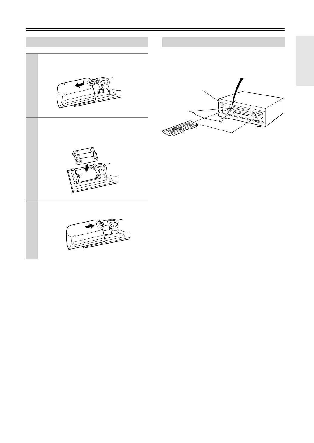
When using the remote controller, point it toward the AV
receiver’s remote control sensor, as shown below.
Notes:
• The remote controller may not work reliably if the AV
receiver is subjected to bright light, such as direct sun-
light or inverter-type fluorescent lights. Keep this in
mind when installing.
• If another remote controller of the same type is used in
the same room, or the AV receiver is installed close to
equipment that uses infrared rays, the remote control-
ler may not work reliably.
• Don’t put anything on top of the remote controller,
such as a book or magazine, because a button may be
pressed continuously, thereby draining the batteries.
• The remote controller may not work reliably if the AV
receiver is installed in a rack behind colored glass
doors. Keep this in mind when installing.
• The remote controller will not work if there’s an obsta-
cle between it and the AV receiver’s remote control
sensor.
Installing the Batteries
1
To open the battery compartment, press
the small hollow and slide open the cover.
2
Insert the three supplied batteries (AA/R6)
in accordance with the polarity diagram
inside the battery compartment.
3
Slide the cover shut.
Using the Remote Controller
30˚
30˚
Approx. 16 ft.
(5 m)
Remote control sensor
Standby indicator
AV receiver
16
Remote Controller
—Continued
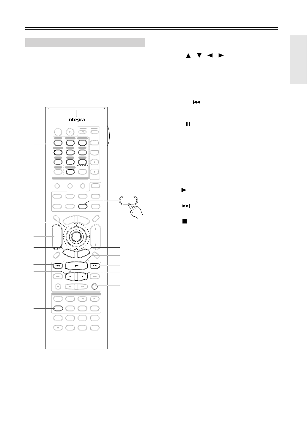
As well as the AV receiver, you can also use the remote
controller to control your other AV components. The
remote controller has a specific operating mode for use
with each type of component. Modes are selected by
using the Remote Mode buttons.
■
Receiver/Tape Mode
In Receiver/Tape mode, you can control the AV receiver
and an Onkyo cassette recorder connected via .
■
DVD Mode
By default, you can control an Integra/Onkyo DVD
player in this mode. By entering the appropriate remote
control code, you can control components made by other
manufacturers (see page 132).
■
CD/CDR/MD Mode
By default, you can control an Integra/Onkyo CD player
in this mode. By entering the appropriate remote control
code, you can control a CD player, MD recorder, or CD
recorder made by another manufacturer (see page 132).
■
Dock Mode
This mode is for controlling an Apple iPod in an Onkyo
RI Dock. By default, you can control an RI Dock that has
a remote control sensor, such as the DS-A2. To control
an RI Dock that’s connected via , you must enter the
appropriate remote control code first (see page 132).
■
TV and VCR Modes
With these modes, you can control a TV and VCR. You
must enter the appropriate remote control code first (see
page 132).
■
Cable/SAT Mode
In Cable/SAT mode, you can control a cable or satellite
TV receiver. You must enter the appropriate remote con-
trol code first (see page 132).
■
Net/USB Mode
This mode is for playing music files on a networked
computer, media server, or USB mass storage device, or
for listening to Internet radio.
■
Zone 2/Zone 3 Modes
These modes are for controlling Zone 2 and Zone 3 (see
page 128).
Receiver/Tape mode is used to control the AV receiver.
It can also be used to control an Onkyo cassette recorder
connected via .
To set the remote controller to Receiver/Tape mode,
press the [Receiver] Remote Mode button.
Note:
• Some of the remote controller functions described in
this manual may not work as expected with other com-
ponents.
About the Remote Controller Modes
1
Use the Remote Mode buttons to select a
mode.
2
Use the buttons supported by that mode
to control the component.
Receiver/Tape mode: see right column
DVD mode: see page 18
CD/MD/CDR mode: see page 19
Dock mode: see page 20
Net/USB mode: see page 21
TV, VCR, Cable/SAT modes: see page 134
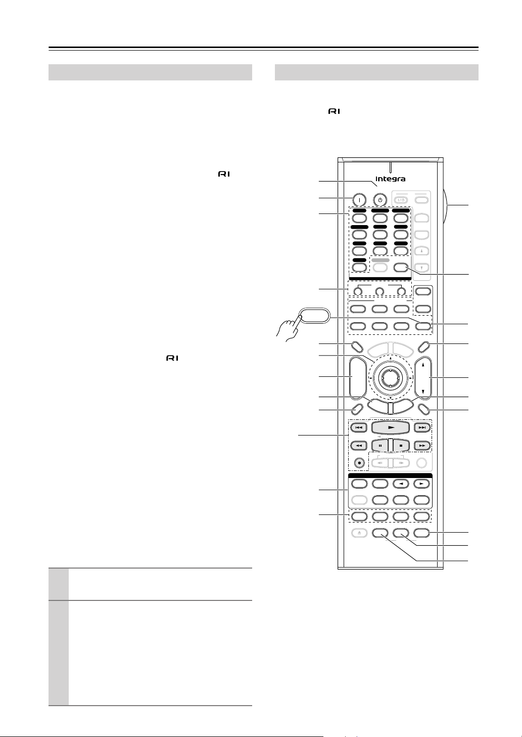
Receiver/Tape Mode
+
-
On Standby
TV
Input
TV CH
TV VOL
--
/
---
10 11 12
D.TUN
+10
0
Clear
123
456
789
Input Selector
VCR
/
DVR CBL
/
SAT
DVD
Tape
Tuner
CD
Phono
Game
/
TV
Macro
123
VCRDVD CD
Zone
2
Remote Mode
Dimmer
Tape/AMP
Sleep
Receiver
TV
Cable
VOL
CH
Disc
Album
+
-
Enter
T
o
p
M
e
n
u
M
e
n
u
Display Muting
E
x
i
t
G
u
i
d
e
Prev
CH
R
e
t
u
r
n
S
e
t
u
p
Audio
Repeat
Play Mode
Open/Close
Listening Mode
DVD HDD
Playlist
RandomRec
Test Tone
CH Sel
Direct
Stereo
Level
+
Level
-
L Night
Audio Sel
THX All ST
Re-EQ
Subtitle
Video Off
VCR
Surround
SAT
Zone
3
AUX 1 AUX 2
Net/USB
CDR/MD/Dock
Net/USB
RC-688M
Tape/AMP
Receiver
1
B
K
H
F
5
I
A
R
S
T
U
G
J
C
D
P
O
N
Q
M
L
17
Remote Controller
—Continued
For detailed information, see the pages in parentheses.
A
Standby button (46)
Sets the AV receiver to Standby.
B
On button (46)
Turns on the AV receiver.
C
Input Selector buttons (62)
Used to select the input source.
D
Macro buttons (136)
Used with the Macro function.
E
Dimmer button (83)
Adjusts the display brightness.
F
Arrow [ ]/[ ]/[ ]/[ ] and Enter buttons
Used to select and adjust settings.
G
CH +/– button (82)
Selects radio presets.
H
Setup button
Used to change settings.
I
Display button (84)
Displays information about the current input source.
J
Listening Mode buttons (88)
Used to select the listening modes. The [Stereo],
[Surround], and Listening Mode [ ]/[ ] buttons
can be used at any time, regardless of the currently
selected remote controller mode.
K
Test Tone, CH Sel, Level–, and Level+
buttons (83, 105)
Used to adjust the level of each speaker.
L
Light button
Turns the remote controller’s illuminated buttons on
or off.
M
D.TUN button (64)
Selects the Direct tuning mode for radio.
N
Remote Mode buttons (16)
Used to select the remote controller modes. When
you press a button, the Remote Mode button for the
currently selected mode lights up.
O
Sleep button (84)
Used with the Sleep function.
P
VOL [ ]/[ ] button (62)
Adjusts the volume of the AV receiver regardless of
the currently selected remote controller mode.
Q
Return button
Returns to the previous display when changing set-
tings.
R
Muting button (83)
Mutes or unmutes the AV receiver.
S
Re-EQ button (86)
Turns the Re-EQ function on or off.
T
L Night button (86)
Turns the Late Night function on or off.
U
Audio Sel button (85)
Selects the audio input: analog, digital, HDMI, or
multichannel.
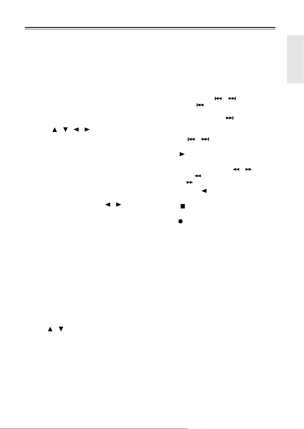
■
TAPE mode
On twin cassette decks, only Deck B can be controlled.
1
Previous and Next [ ]/[ ] buttons
The Previous [ ] button selects the previous
track. During playback it selects the beginning of
the current track. The Next [ ] button selects the
next track.
Depending on how they were recorded, the Previous
and Next [ ]/[ ] buttons may not work prop-
erly with some cassette tapes.
Play [ ] button
Starts playback.
Rewind and Fast Forward [ ]/[ ] buttons
The Rewind [ ] button starts rewind. The Fast
Forward [ ] button starts fast forward.
Reverse Play [ ] button
Starts reverse playback.
Stop [ ] button
Stops playback.
Rec [ ] button
Starts recording.
18
Remote Controller
—Continued
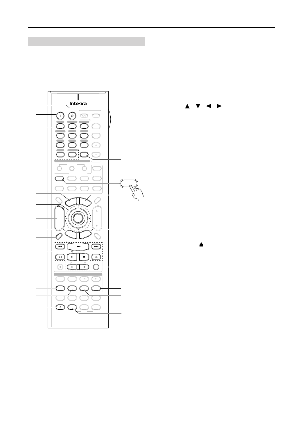
To set the remote controller to DVD mode, press the
[DVD] Remote Mode button.
A
Standby button
Sets the DVD player to Standby.
B
On button
Turns on the DVD player.
C
Number buttons
Used to enter title, chapter, and track numbers, and
to enter times for locating specific points.
D
Top Menu button
Selects a DVD’s top menu.
E
Arrow [ ]/[ ]/[ ]/[ ] and Enter buttons
Used to navigate menus and select items.
F
Disc +/– button
Selects discs on a DVD changer.
G
Setup button
Used to access the DVD player’s settings.
H
Display button
Displays information about the current disc, title,
chapter, or track, including elapsed time, remaining
time, total time, and so on.
I
Playback buttons
From left to right: Previous, Play, Next, Rewind,
Pause, Stop, Fast Forward, Slow Reverse, and Slow
Forward.
J
Repeat button
Used with the repeat playback function.
K
Audio button
Selects foreign language soundtracks and audio for-
mats (e.g., Dolby Digital or DTS).
L
Open/Close [ ] button
Opens and closes the disc tray.
M
Clear button
Cancels functions and clears entered numbers.
N
Menu button
Displays a DVD’s menu.
O
Return button
Exits the DVD player’s onscreen setup menu.
P
Random button
Used with the random playback function.
Q
Play Mode button
Selects play modes on components with selectable
play modes.
R
Subtitle button
Selects subtitles.
S
Video Off button
Turns off the internal video circuitry, eliminating
any possibility of interference.
DVD Mode
+
-
On Standby
TV
Input
TV CH
TV VOL
--
/
---
10 11 12
D.TUN
+10
0
Clear
123
456
789
Input Selector
VCR
/
DVR CBL
/
SAT
DVD
Tape
Tuner
CD
Phono
Game
/
TV
Macro
123
VCRDVD CD
Zone
2
Remote Mode
Dimmer
Tape/AMP
Sleep
Receiver
TV
Cable
VOL
CH
Disc
Album
+
-
Enter
T
o
p
M
e
n
u
M
e
n
u
Display Muting
E
x
i
t
G
u
i
d
e
Prev
CH
R
e
t
u
r
n
S
e
t
u
p
Audio
Repeat
Play Mode
Open/Close
Listening Mode
DVD HDD
Playlist
RandomRec
Test Tone
CH Sel
Direct
Stereo
Level
+
Level
-
L Night
Audio Sel
THX All ST
Re-EQ
Subtitle
Video Off
VCR
Surround
SAT
Zone
3
AUX 1 AUX 2
Net/USB
CDR/MD/Dock
Net/USB
RC-688M
L
B
G
H
M
Q
R
S
F
E
I
C
D
A
O
N
P
J
K
DVD
19
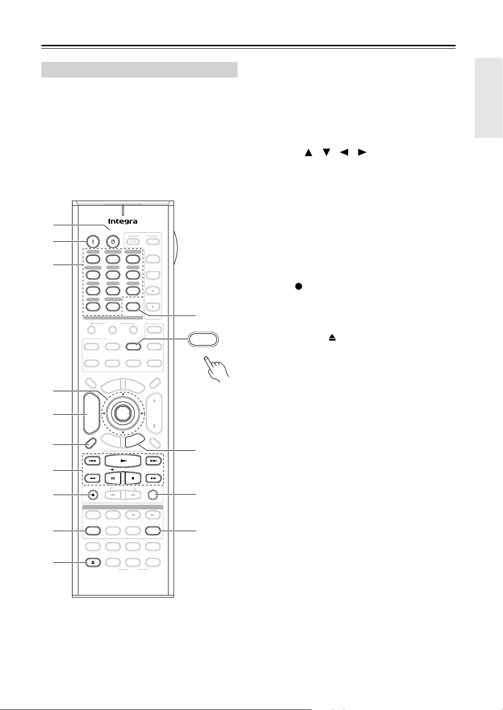
Remote Controller
—Continued
To control an Integra/Onkyo CD player, MD
recorder, or CD recorder, or a CD or MD
player/recorder made by another manufacturer,
press the [CD] Remote Mode button to select the
CD/MD/CDR remote controller mode.
In order to control an Onkyo MD recorder or CD
recorder, or a component made by another manufacturer,
you must first enter the appropriate remote control code
(see page 132).
A
Standby button
Sets the component to Standby.
B
On button
Set the component to On or Standby.
C
Number buttons
Used to enter track numbers and times for locating
specific points.
D
Arrow [ ]/[ ]/[ ]/[ ] and Enter buttons
Used with some components.
E
Disc +/– button
Selects discs on a CD changer.
F
Display button
Displays information about the current disc or track,
including elapsed time, remaining time, total time,
and so on.
G
Playback buttons
From left to right: Previous, Play, Next, Rewind,
Pause, Stop, and Fast Forward.
H
Rec [ ] button
Starts recording.
I
Repeat button
Used with the repeat playback function.
J
Open/Close [ ] button
Opens or closes the disc tray or ejects the MiniDisc.
K
Clear button
Cancels functions and clears entered numbers.
L
Return button
Used with some components.
M
Random button
Used with the random playback function.
N
Play Mode button
Selects play modes on components with selectable
play modes.
CD/MD/CDR Modes
+
-
On Standby
TV
Input
TV CH
TV VOL
--
/
---
10 11 12
D.TUN
+10
0
Clear
123
456
789
Input Selector
VCR
/
DVR CBL
/
SAT
DVD
Tape
Tuner
CD
Phono
Game
/
TV
Macro
123
VCRDVD CD
Zone
2
Remote Mode
Dimmer
Tape/AMP
Sleep
Receiver
TV
Cable
VOL
CH
Disc
Album
+
-
Enter
T
o
p
M
e
n
u
M
e
n
u
Display Muting
E
x
i
t
G
u
i
d
e
Prev
CH
R
e
t
u
r
n
S
e
t
u
p
Audio
Repeat
Play Mode
Open/Close
Listening Mode
DVD HDD
Playlist
RandomRec
Test Tone
CH Sel
Direct
Stereo
Level
+
Level
-
L Night
Audio Sel
THX All ST
Re-EQ
Subtitle
Video Off
VCR
Surround
SAT
Zone
3
AUX 1 AUX 2
Net/USB
CDR/MD/Dock
Net/USB
RC-688M
B
K
F
7
8
9
J
E
L
C
D
A
M
N
CDR/MD/Dock
CD

20
Remote Controller
—Continued
Dock mode is for controlling an Apple iPod in an Onkyo
RI Dock.
To control an RI Dock, press the [CD] REMOTE
MODE button to select the Dock remote controller
mode.
In order to control an RI Dock, you must first enter the
appropriate remote control code (see page 132).
When Using an RI Dock:
• Connect the RI Dock to the TAPE IN or GAME/TV
IN L/R jacks.
• Set the RI Dock’s RI MODE switch to HDD or
HDD/DOCK.
• Set the AV receiver’s Input Display to DOCK (see
page 52).
• See to the RI Dock’s instruction manual for more
information.
A
Standby button
Turns off the iPod.
B
On button*
Turns on the iPod.
C
Top Menu button
Works as a Mode button when used with a DS-A2
RI Dock.
D
Arrow [ ]/[ ] and Enter buttons*
Used to navigate menus and select items.
E
Album +/– button*
Selects the next or previous album.
F
Display button*
Turns on the backlight for 30 seconds.
G
Previous [ ] button
Restarts the current song. Press it twice to select the
previous song.
H
Pause [ ] button
Pauses playback. (With 3rd generation iPods, it
works as a Play/Pause button.)
I
Rewind [ ] button
Press and hold to rewind.
J
Playlist [ ]/[ ] buttons*
Used to select the previous or next playlist on the
iPod.
K
Repeat button*
Used with the repeat function.
L
Menu button*
Used to access menus.
M
Play [ ] button
Starts playback. If the component is off, it will turn
on automatically. (With 3rd generation iPods, this
button works as a Play/Pause button.)
N
Next [ ] button
Selects the next song.
O
Stop [ ] button
Stops playback and displays a menu.
P
Fast Forward [ ] button
Press and hold to fast forward.
Q
Random button*
Used with the shuffle function.
R
Play Mode button
Used to select play modes on components with
selectable play modes.
Works as a Resume button when used with a DS-A2
RI Dock.
*Buttons marked with an asterisk (*) are not supported
by 3rd generation iPods.
Dock Mode
+
-
On Standby
TV
Input
TV CH
TV VOL
--
/
---
10 11 12
D.TUN
+10
0
Clear
123
456
789
Input Selector
VCR
/
DVR CBL
/
SAT
DVD
Tape
Tuner
CD
Phono
Game
/
TV
Macro
123
VCRDVD CD
Zone
2
Remote Mode
Dimmer
Tape/AMP
Sleep
Receiver
TV
Cable
VOL
CH
Disc
Album
+
-
Enter
T
o
p
M
e
n
u
M
e
n
u
Display Muting
E
x
i
t
G
u
i
d
e
Prev
CH
R
e
t
u
r
n
S
e
t
u
p
Audio
Repeat
Play Mode
Open/Close
Listening Mode
DVD HDD
Playlist
RandomRec
Test Tone
CH Sel
Direct
Stereo
Level
+
Level
-
L Night
Audio Sel
THX All ST
Re-EQ
Subtitle
Video Off
VCR
Surround
SAT
Zone
3
AUX 1 AUX 2
Net/USB
CDR/MD/Dock
Net/USB
RC-688M
B
N
7
6
4
5
C
A
P
O
Q
R
8
9
J
K
M
L
CD
CDR/MD/Dock
21
Remote Controller
—Continued
Net/USB mode is for playing music files on a networked
computer, media server, or USB mass storage device, or
for listening to Internet radio.
To set the remote controller to Net/USB mode, press
the [Net/USB] Remote Mode button.
A
Number buttons
Used to enter track numbers.
B
Arrow [ ]/[ ]/[ ]/[ ] and Enter buttons
Used to navigate menus and select items.
C
CH +/– button
Used to select Internet radio stations.
D
Setup button
Displays the URL input screen for Internet radio.
E
Previous [ ] button
Restarts the current song. Press it twice to select the
previous song.
F
Pause [ ] button
Pauses playback of music stored on a USB mass
storage device.
G
Repeat button
Used with the repeat playback function, which can
be used with music files on a networked computer,
media server, or USB mass storage device.
H
Return button
Returns to the previous display.
I
Play [ ] button
Starts playback.
J
Next [ ] button
Selects the next song.
K
Stop [ ] button
Stops playback.
L
Random button
Used with the random playback function, which can
be used with music files on a networked computer,
media server, or USB mass storage device.
Net/USB Mode
+
-
On Standby
TV
Input
TV CH
TV VOL
--
/
---
10 11 12
D.TUN
+10
0
Clear
123
456
789
Input Selector
VCR
/
DVR CBL
/
SAT
DVD
Tape
Tuner
CD
Phono Net/USB
Game
/
TV
Macro
12
3
VCRDVD
CDR/MD/Dock
CD
Zone
2
Remote Mode
Dimmer
Tape/AMP
Sleep
Receiver
TV
Net/USB
Cable
VOL
CH
Disc
Album
+
-
Enter
T
o
p
M
e
n
u
M
e
n
u
Display Muting
E
x
i
t
G
u
i
d
e
Prev
CH
R
e
t
u
r
n
S
e
t
u
p
RC-688M
Audio
Repeat
Play Mode
Open/Close
Listening Mode
DVD HDD
Playlist
RandomRec
Test Tone
CH Sel
Direct
Stereo
Level
+
Level
-
L Night
Audio Sel
THX All ST
Re-EQ
Subtitle
Video Off
VCR
Surround
SAT
Zone
3
AUX 1 AUX 2
4
6
3
2
5
1
7
Net/USB
8
9
J
K
L
22
Connecting Your Speakers
Thanks to the AV receiver’s superb capabilities, you can enjoy surround sound with a real sense of movement in your
own home—just like being in a movie theater or concert hall. You can enjoy DVDs featuring Dolby Digital or DTS.
With analog or digital TV, you can enjoy Dolby Pro Logic IIx, DTS Neo:6, or Onkyo’s original DSP listening modes.
You can also enjoy THX Surround EX (THX-certified THX speaker system recommended).
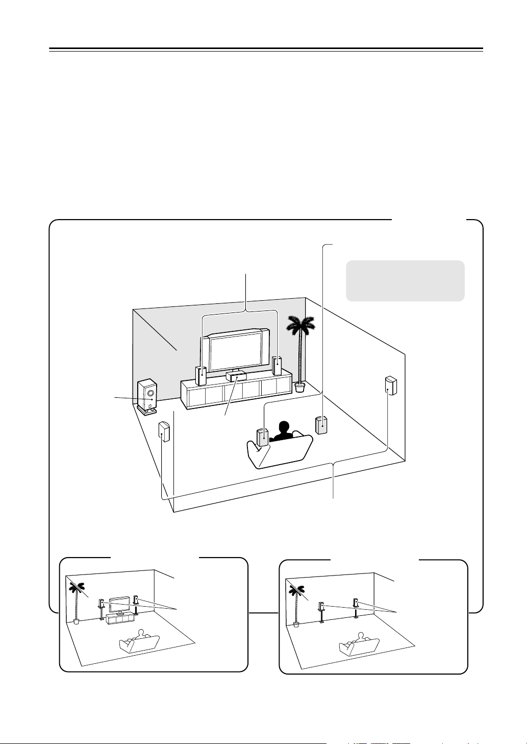
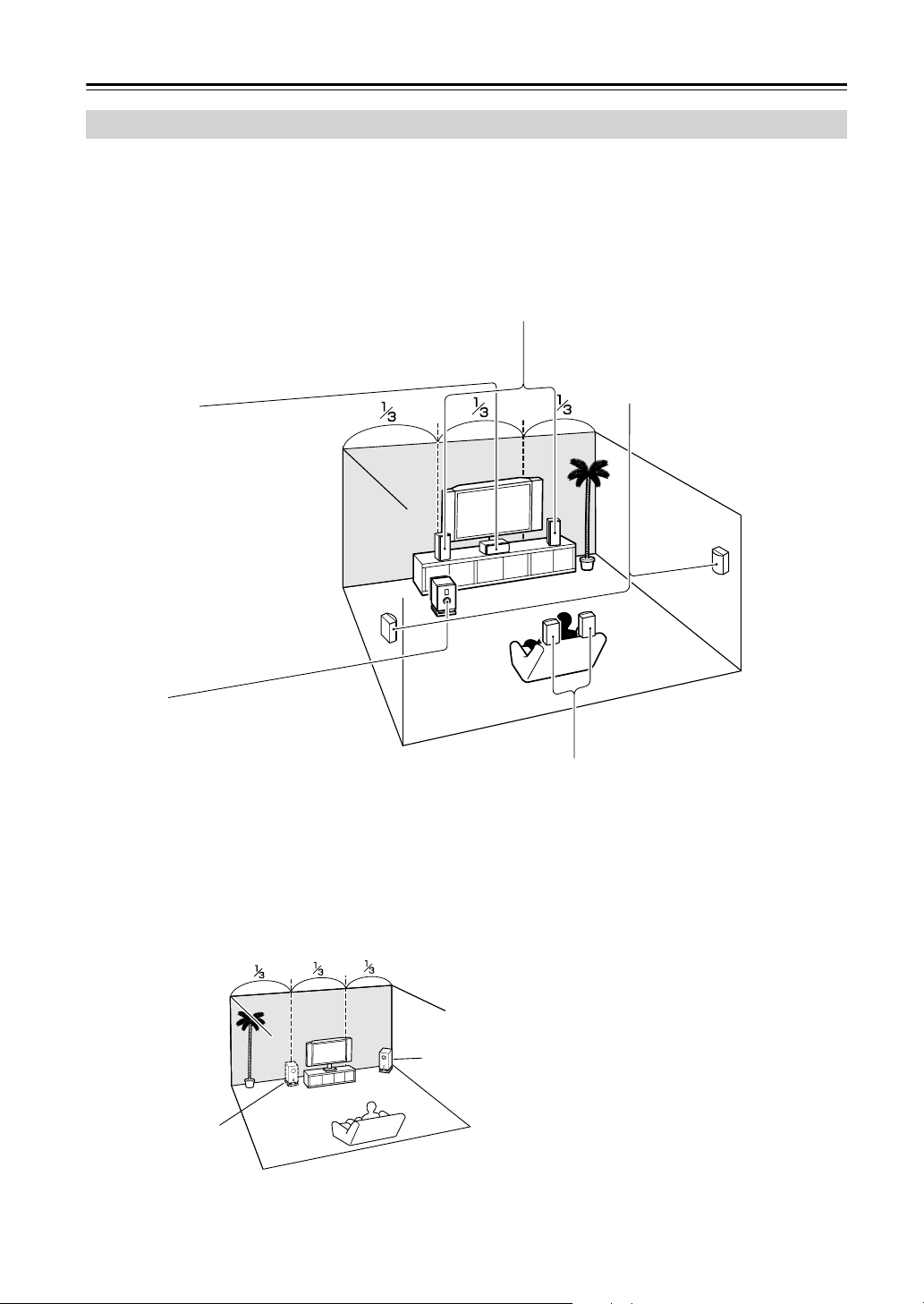
Enjoying Home Theater
Corner
position
1/3 of wall
position
Surround back left and right speakers
These speakers are necessary to enjoy Dolby Digital
EX, DTS-ES Matrix, DTS-ES Discrete, THX Surround
EX, etc. They enhance the realism of surround sound
and improve sound localization behind the listener. Posi-
tion them behind the listener about 2–3 feet
(60–100 cm) above ear level.
Surround left and right speakers
These speakers are used for precise
sound positioning and to add realistic
ambience.
Position them at the sides of the lis-
tener, or slightly behind, about 2–3 feet
(60–100 cm) above ear level. Ideally
they should be equally spaced from the
listener.
Center speaker
This speaker enhances the front left
and right speakers, making sound
movements distinct and providing a
full sound image. For movies it’s used
mainly for dialog.
Position it close to your TV (preferably
on top) facing forward at about ear
level, or at the same height as the
front left and right speakers.
Subwoofer
The subwoofer handles the bass sounds of
the LFE (Low-Frequency Effects) channel.
The volume and quality of the bass output
from your subwoofer will depend on its posi-
tion, the shape of your listening room, and
your listening position. In general, a good bass
sound can be obtained by installing the sub-
woofer in a front corner, or at one-third the way
along the front wall, as shown.
Tip: To find the best position for your sub-
woofer, while playing a movie or some music
with good bass, experiment by placing your
subwoofer at various positions within the
room and choose the
one that provides
the most satisfying
results.
Front left and right speakers
These output the main sound. Their role in a home theater is to provide a solid
anchor for the sound image. They should be positioned facing the listener at
about ear level, and equally spaced from the TV. Angle them inward slightly so
as to create a triangle, with the listener at the apex.
23
Connecting Your Speakers
—Continued
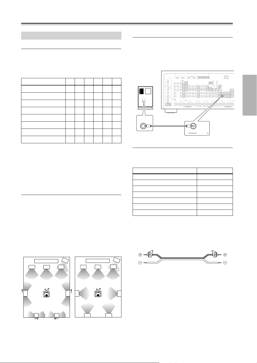
Speaker Configuration
For the best surround-sound experience, you should con-
nect seven speakers and a powered subwoofer.
The following table shows which channels you should
use based on the number of speakers you have.
* If you’re using only one surround back speaker, use the SURR
BACK L terminals.
No matter how many speakers you use, a powered sub-
woofer is recommended for a powerful and solid bass.
To get the best from your surround-sound system, you
must set the speaker settings. You can do this automati-
cally (see page 55) or manually (see page 101).
Using Dipole Speakers
You can use dipole speakers for the surround left and
right and surround back left and right speakers. Dipole
speakers output the same sound in two directions.
Dipole speakers typically have an arrow printed on them to
indicate how they should be positioned. The surround left
and right dipole speakers should be positioned so that their
arrows point toward your TV or screen, while the surround
back left and right dipolar speakers should be positioned
so that their arrows point toward each other, as shown.
Connecting a Powered Subwoofer
Using a suitable cable, connect the AV receiver’s SUB-
WOOFER PRE OUT to the input on your powered sub-
woofer. If your subwoofer is unpowered and you’re
using an external amplifier, connect the SUBWOOFER
PRE OUT to the amp’s input.
Attaching the Speaker Labels
The AV receiver’s positive (+) speaker terminals are
color-coded for ease of identification. (The negative (–)
speaker terminals are all black.)
The supplied speaker labels are also color-coded and you
should attach them to the positive (+) side of each
speaker cable in accordance with the above table. All you
need to do then is to match the color of each label to the
corresponding speaker terminal.
Connecting Your Speakers
Number of speakers: 234567
Front left
✓✓✓✓✓✓
Front right
✓✓✓✓✓✓
Center
✓ ✓✓✓
Surround left
✓✓✓✓
Surround right
✓✓✓✓
Surround back*
✓
Surround back left
✓
Surround back right
✓
2
1
3
4
2
1
3
4
5
6
78
5
7 8
6
TV/screen TV/screen
1. Subwoofer
2. Front left speaker
3. Center speaker
4. Front right speaker
5. Surround left speaker
6. Surround right speaker
7. Surround back left
speaker
8. Surround back right
speaker
Dipole speakers
Normal speakers
Speaker terminal Color
Front left, Zone 2 left White
Front right, Zone 2 right Red
Center Green
Surround left Blue
Surround right Gray
Surround back left Brown
Surround back right Tan
FRONT L
(BTL)
FRONT R
(BTL)
V
S
MONITOR
OUT
ZONE 2
OUT
RS232
DIGITAL
COAXIAL
OPTICAL
REMOTE
CONTROL
IN 1
IN 1
IN 2
IN IN IN IN
PHONO
FRONT R FRONT LSURR R CENTER SURR L
SURR BACK R
CD TAPE AUX 1
GAME/TV
GAME/TV CBL/SAT
CBL/SAT
AUX 1 VCR/DVR
VCR/DVR DVD
DVD
GND
IN 2
IN 3
LL
RR
ASSIGNABLE
(DVD)
(CBL/SAT)
(VCR/DVR)
(GAME/TV)
(CD)
OUT
OUT
IN IN
OUT
IN IN FRONT FRONTCENTER
SUBWOOFER SUBWOOFER
CENTERSURR SURR
MULTI CH
PRE OUT
SURR BACK SURR BACK
Bi-AMP
SURR B
Bi-A
M
ETHERNET
HDMI
IN 1IN 2IN 3IN 4
ASSIGNABLE
OUT
MAIN
OUT
SUB
ZONE2 R
AM
ANTENNA
FM75
COMPONENT VIDEO
ASSIGNABLE
IN 3
Y
CB/PB
CR/PR
IN 2 IN
1(DVD)
MONITOR
OUT 1
MONITOR OUT 2
/ZONE 2 OUT
V
S
ZONE 2 ZO
N
PRE OUT
AB
IR
12V TRIGGER OUT
B
OUT
C
LINE INPUT
SUBWOOFER
PRE OUT
LINE INPUT
Powered
subwoofer
24
Connecting Your Speakers
—Continued
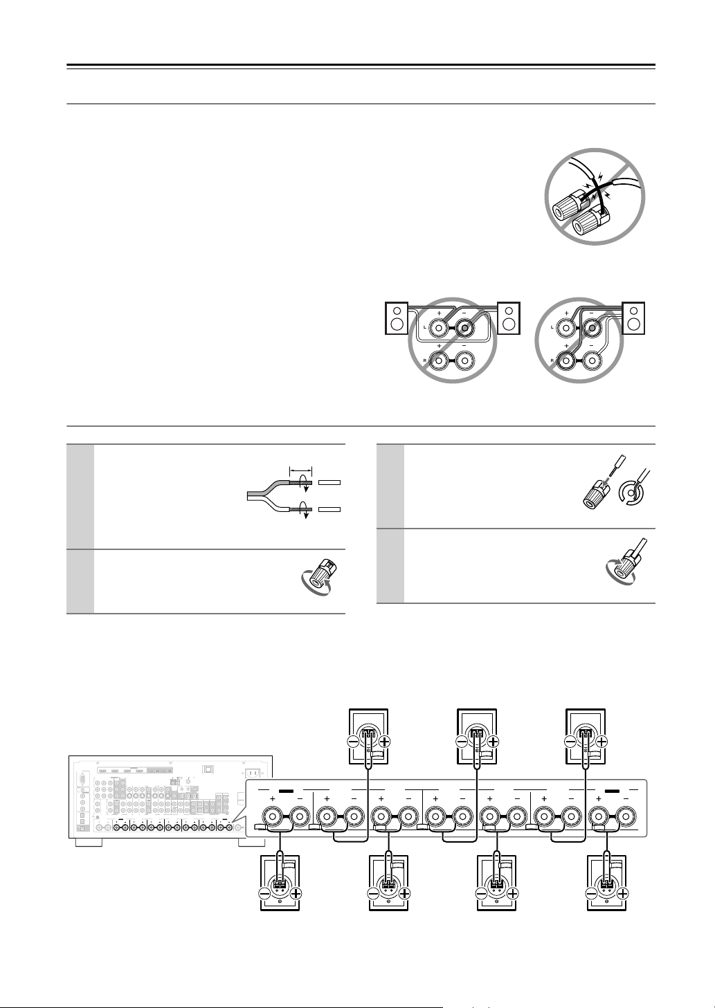
Speaker Connection Precautions
Read the following before connecting your speakers:
•You can connect speakers with an impedance of
between 4 and 16 ohms. If the impedance of any of the
connected speakers is 4 ohms or more but less than 6,
be sure to set the speaker impedance to 4 ohms (see
page 47). If you use speakers with a lower impedance,
and use the amplifier at high volume levels for a long
period of time, the built-in amp protection circuit may
be activated.
• Disconnect the power cord from the wall outlet before
making any connections.
• Read the instructions supplied with your speakers.
•Pay close attention to speaker wiring polarity. Connect
positive (+) terminals to only positive (+) terminals,
and negative (–) terminals to only negative (–) termi-
nals. If you get them the wrong way around, the sound
will be out of phase and will sound unnatural.
• Unnecessarily long or very thin speaker cables may
affect the sound quality and should be avoided.
• Be careful not to short the
positive and negative wires.
Doing so may damage the AV
receiver.
• Don’t connect more than one
cable to each speaker termi-
nal. Doing so may damage the
AV receiver.
• Don’t connect a speaker to several terminals.
Connecting the Speaker Cables
The following illustration shows which speaker should be connected to each pair of terminals.
If you’re using only one surround back speaker, connect it to the SURR BACK L terminals.
1
Strip about 5/8" (15
mm) of insulation from
the ends of the
speaker cables, and
twist the bare wires
tightly, as shown.
2
Unscrew the terminal.
5/8" (15 mm)
3
Fully insert the bare wire.
4
Screw the terminal tight.
RS232
DIGITAL
COAXIAL
OPTICAL
REMOTE
CONTROL
IN 1
IN 1
IN 2
IN IN IN IN
PHONO
ZONE2 R ZONE2 LFRONT R FRONT LSURR R CENTER SURR L
SURR BACK R
CD TAPE AUX 1
GAME/TV
GAME/TV CBL/SAT
CBL/SAT
AUX 1 VCR/DVR
VCR/DVR DVD
DVD
GND
IN 2
IN 3
LL
V
S
RR
ASSIGNABLE
(DVD)
(CBL/SAT)
(VCR/DVR)
(GAME/TV)
(CD)
OUT
COMPONENT VIDEO
ASSIGNABLE
IN 3
Y
C
B
/P
B
C
R
/P
R
IN 2 IN
1(DVD)
MONITOR
OUT 1
OUT
IN IN
OUT
IN IN FRONT FRONTCENTER
SUBWOOFER SUBWOOFER
CENTERSURR SURR
MULTI CH
PRE OUT
SURR BACK SURR BACK
AM
ANTENNA
FM75
AC INLET
Bi-AMP
SURR BACK L
Bi-AMP
ETHERNET
MONITOR OUT 2
/ZONE 2 OUT
ZONE 2 ZONE 3
PRE OUT
L
R
SW
AB
IR
12V TRIGGER OUT
IN
AB
OUT
V
S
MONITOR
OUT
ZONE 2
OUT
C
HDMI
IN 1IN 2IN 3IN 4
ASSIGNABLE
OUT
MAIN
OUT
SUB
FRONT R FRONT LSURR R CENTER SURR L
SURR BACK R
Bi-AMP
SURR BACK L
Bi-AMP
Surround back
left speaker
Surround back
right speaker
Front left speakerFront right speaker Center speaker
Surround right
speaker
Surround left
speaker
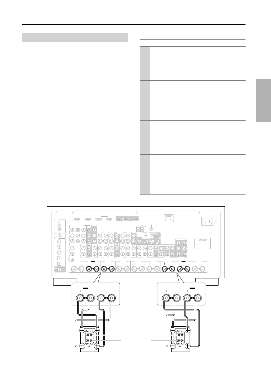
25
Connecting Your Speakers
—Continued
The FRONT L/R and SURR BACK L/R terminal posts
can be used with front speakers and surround back
speakers respectively, or bi-amped to provide separate
tweeter and woofer feeds for a pair of front speakers that
support bi-amping, providing improved bass and treble
performance.
• When bi-amping is used, the AV receiver is able to
drive up to 5.1 speakers in the main room.
•For bi-amping, the FRONT L/R terminal posts con-
nect to the front speakers’ tweeter terminals. And the
SURR BACK L/R terminal posts connect to the front
speakers’ woofer terminals.
• Once you’ve completed the bi-amping connections
shown below and turned on the AV receiver, you must
set the Speaker Type setting to Bi-Amp to enable bi-
amping (see page 47).
Important:
• When making the bi-amping connections, be sure
to remove the jumper bars that link the speakers’
tweeter (high) and woofer (low) terminals.
• Bi-amping can only be used with speakers that support
bi-amping. Refer to your speaker manual.
Bi-amping Speaker Hookup
Bi-amping the Front Speakers
1
Connect the AV receiver’s FRONT R positive (+)
terminal to the right speaker’s positive (+) tweeter
(high) terminal. And connect the AV receiver’s
FRONT R negative (–) terminal to the right
speaker’s negative (–) tweeter (high) terminal.
2
Connect the AV receiver’s SURR BACK R posi-
tive (+) terminal to the right speaker’s positive (+)
woofer (low) terminal. And connect the AV
receiver’s SURR BACK R negative (–) terminal to
the right speaker’s negative (–) woofer (low) ter-
minal.
3
Connect the AV receiver’s FRONT L positive (+)
terminal to the left speaker’s positive (+) tweeter
(high) terminal. And connect the AV receiver’s
FRONT L negative (–) terminal to the left
speaker’s negative (–) tweeter (high) terminal.
4
Connect the AV receiver’s SURR BACK L posi-
tive (+) terminal to the left speaker’s positive (+)
woofer (low) terminal. And connect the AV
receiver’s SURR BACK L negative (–) terminal to
the left speaker’s negative (–) woofer (low) ter-
minal.
RS232
DIGITAL
COAXIAL
OPTICAL
REMOTE
CONTROL
IN 1
IN 1
IN 2
IN IN IN IN
PHONO
ZONE2 R ZONE2 LFRONT R FRONT LSURR R CENTER SURR L
SURR BACK R
CD TAPE AUX 1
GAME/TV
GAME/TV CBL/SAT
CBL/SAT
AUX 1 VCR/DVR
VCR/DVR DVD
DVD
GND
IN 2
IN 3
LL
V
S
RR
ASSIGNABLE
(DVD)
(CBL/SAT)
(VCR/DVR)
(GAME/TV)
(CD)
OUT
COMPONENT VIDEO
ASSIGNABLE
IN 3
Y
C
B
/P
B
C
R
/P
R
IN 2 IN
1(DVD)
MONITOR
OUT 1
OUT
IN IN
OUT
IN IN FRONT FRONTCENTER
SUBWOOFER SUBWOOFER
CENTERSURR SURR
MULTI CH
PRE OUT
SURR BACK SURR BACK
AM
ANTENNA
FM75
AC INLET
Bi-AMP
SURR BACK L
Bi-AMP
ETHERNET
MONITOR OUT 2
/ZONE 2 OUT
ZONE 2 ZONE 3
PRE OUT
L
R
SW
AB
IR
12V TRIGGER OUT
IN
AB
OUT
V
S
MONITOR
OUT
ZONE 2
OUT
C
HDMI
IN 1IN 2IN 3IN 4
ASSIGNABLE
OUT
MAIN
OUT
SUB
FRONT R
SURR BACK R
Bi-AMP
FRONT L
SURR BACK L
Bi-AMP
Right speaker Left speaker
Tw eeter (high)
Woofer (low)
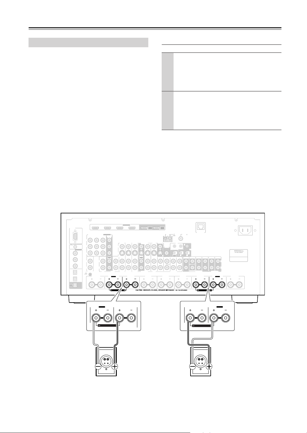
26
Connecting Your Speakers
—Continued
The FRONT L/R and SURR BACK L/R terminal posts
can be used with front speakers and surround back
speakers respectively, or bridged together to provide
almost double the output power for the front speakers.
• When bridging is used, the AV receiver is able to drive
2 speakers in the main room (2.1 speakers if you’re
using a powered subwoofer).
•For bridging, the positive (+) FRONT L/R and SURR
BACK L/R terminal posts are used, but the negative
(–) FRONT L/R and SURR BACK L/R terminals are
not.
• Once you’ve completed the bridging connections
shown below and turned on the AV receiver, you must
set the Speaker Type setting to BTL to enable bridging
(see page 47).
Notes:
• Use only front speakers with an impedance of 8
ohms or higher for bridging. Failure to do so may
seriously damage the AV receiver.
• When using bridging, make sure that your front speak-
ers can handle the additional power.
Bridged Speaker Hookup
Bridging the Front Speakers
1
Connect the AV receiver’s FRONT R positive (+)
terminal to the right speaker’s positive (+) ter-
minal. And connect the AV receiver’s SURR
BACK R positive (+) terminal to the right
speaker’s negative terminal.
2
Connect the AV receiver’s FRONT L positive (+)
terminal to the left speaker’s positive (+) terminal.
And connect the AV receiver’s SURR BACK L
positive (+) terminal to the left speaker’s negative
terminal.
FRONT L
(BTL)
FRONT R
(BTL)
V
S
MONITOR
OUT
ZONE 2
OUT
RS232
DIGITAL
COAXIAL
OPTICAL
REMOTE
CONTROL
IN 1
IN 1
IN 2
IN IN IN IN
PHONO
ZONE2 L
FRONT R FRONT LSURR R CENTER SURR L
SURR BACK R
CD TAPE AUX 1
GAME/TV
GAME/TV CBL/SAT
CBL/SAT
AUX 1 VCR/DVR
VCR/DVR DVD
DVD
GND
IN 2
IN 3
LL
V
S
RR
ASSIGNABLE
(DVD)
(CBL/SAT)
(VCR/DVR)
(GAME/TV)
(CD)
OUT
COMPONENT VIDEO
ASSIGNABLE
IN 3
Y
C
B
/P
B
C
R
/P
R
IN 2 IN
1(DVD)
MONITOR
OUT
OUT
IN IN
OUT
IN IN FRONT FRONTCENTER
SUBWOOFER SUBWOOFER
CENTERSURR SURR ZONE 2 ZONE 3
MULTI CH
PRE OUT PRE OUT
SURR BACK SURR BACK
L
R
AC INLET
Bi-AMP
SURR BACK L
Bi-AMP
ETHERNET
HDMI
IN 1IN 2IN 3IN 4
ASSIGNABLE
OUT
MAIN
OUT
SUB
ZONE2 R
AM
ANTENNA
FM75
AB
IR
12V TRIGGER OUT
IN
AB
OUT
C
FRONT L
(BTL)
FRONT R
FRONT R
(BTL)
SURR BACK R
Bi-AMP
FRONT L
SURR BACK L
Bi-AMP
Right speaker Left speaker
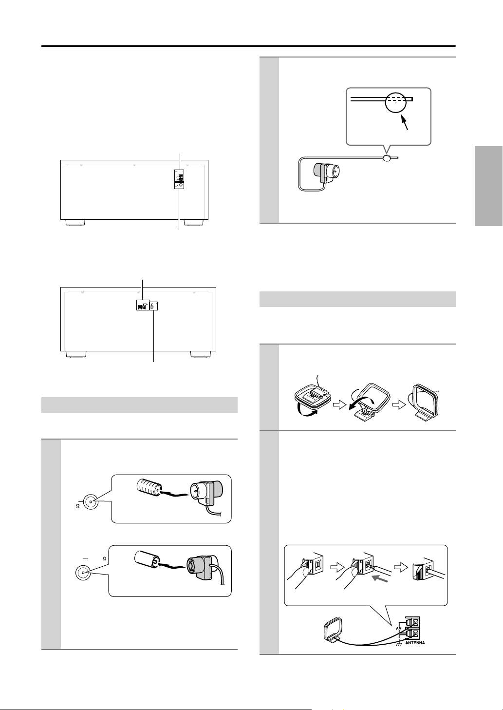
27
Connecting Antennas
This section explains how to connect the supplied indoor
FM antenna and AM loop antenna, and how to connect
commercially available outdoor FM and AM antennas.
The AV receiver won’t pick up any radio signals without
any antenna connected, so you must connect the antenna
to use the tuner.
■
North American Model
■
Other Models
The supplied indoor FM antenna is for indoor use only.
If you cannot achieve good reception with the supplied
indoor FM antenna, try a commercially available out-
door FM antenna instead (see page 28).
The supplied indoor AM loop antenna is for indoor use
only.
Connecting the Indoor FM Antenna
1
Attach the FM antenna, as shown.
■
North American Model
■
Other Models
Once your AV receiver is ready for use, you’ll
need to tune into an FM radio station and adjust
the position of the FM antenna to achieve the best
possible reception.
AM
ANTENNA
FM
75
HD RADIO
AM antenna push terminals
FM antenna jack
AM
ANTENNA
FM75
AM antenna push terminals
FM antenna jack
FM
75
Insert the plug fully
into the jack.
FM75
Insert the plug fully
into the jack.
2
Use thumbtacks or something similar to
fix the FM antenna into position.
Caution:
Be careful that you don’t injure yourself
when using thumbtacks.
Connecting the AM Loop Antenna
1
Assemble the AM loop antenna, inserting
the tabs into the base, as shown.
2
Connect both wires of the AM loop
antenna to the AM push terminals, as
shown.
(The antenna’s wires are not polarity sensitive, so
they can be connected either way around).
Make sure that the wires are attached securely and
that the push terminals are gripping the bare
wires, not the insulation.
■
North American Model
Thumbtacks, etc.
Push Insert wire Release
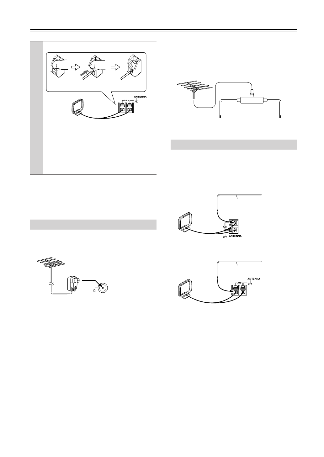
28
Connecting Antennas
—Continued
If you cannot achieve good reception with the supplied
indoor AM loop antenna, try using it with a commer-
cially available outdoor AM antenna (see page 28).
If you cannot achieve good reception with the supplied
indoor FM antenna, try a commercially available out-
door FM antenna instead.
Notes:
• Outdoor FM antennas work best outside, but usable
results can sometimes be obtained when installed in an
attic or loft.
•For best results, install the outdoor FM antenna well
away from tall buildings, preferably with a clear line
of sight to your local FM transmitter.
• Outdoor antenna should be located away from possi-
ble noise sources, such as neon signs, busy roads, etc.
•For safety reasons, outdoor antenna should be situated
well away from power lines and other high-voltage
equipment.
• Outdoor antenna must be grounded in accordance
with local regulations to prevent electrical shock haz-
ards.
■
Using a TV/FM Antenna Splitter
It’s best not to use the same antenna for both FM and TV
reception, as this can cause interference problems. If cir-
cumstances demand it, use a TV/FM antenna splitter, as
shown.
If good reception cannot be achieved using the supplied
AM loop antenna, an outdoor AM antenna can be used in
addition to the loop antenna, as shown.
■
North American Model
■
Other Models
Outdoor AM antennas work best when installed horizon-
tally outside, but good results can sometimes be obtained
indoors by mounting horizontally above a window. Note
that the AM loop antenna should be left connected.
Outdoor antenna must be grounded in accordance with
local regulations to prevent electrical shock hazards.
■
Other Models
Once your AV receiver is ready for use, you’ll
need to tune into an AM radio station and adjust
the position of the AM antenna to achieve the best
possible reception.
Keep the antenna as far away as possible from
your AV receiver, TV, speaker cables, and power
cords.
Connecting an Outdoor FM Antenna
Push Insert wire Release
FM
75
North American
model is shown
Connecting an Outdoor AM Antenna
To AV receiver To TV (or VCR)
TV/FM antenna splitter
Outdoor antenna
AM loop antenna
Insulated antenna cable
Outdoor antenna
AM loop antenna
Insulated antenna cable
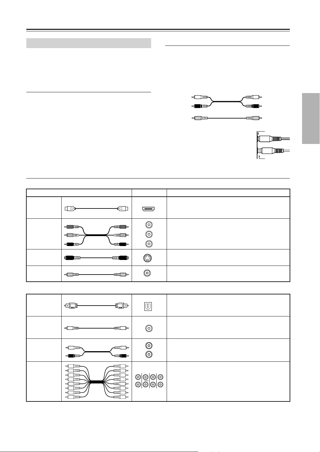
29
Connecting Your Components
• Before making any AV connections, read the manuals
supplied with your other AV components.
• Don’t connect the power cord until you’ve completed
and double-checked all AV connections.
Optical Digital Jacks
The AV receiver’s optical digital jacks have shutter-type
covers that open when an optical plug is inserted and
close when it’s removed. Push plugs in all the way.
Caution:
To prevent shutter damage, hold the optical
plug straight when inserting and removing.
AV Connection Color Coding
RCA-type AV connections are usually color coded: red,
white, and yellow. Use red plugs to connect right-
channel audio inputs and outputs (typically labeled “R”).
Use white plugs to connect left-channel audio inputs and
outputs (typically labeled “L”). And use yellow plugs to
connect composite video inputs and outputs.
• Push plugs in all the way to make
good connections (loose connections
can cause noise or malfunctions).
•To prevent interference, keep audio
and video cables away from power
cords and speaker cables.
AV Cables and Jacks
Note:
The AV receiver does not support SCART connections.
About AV Connections
Left (white)
Right (red)
(Yellow)
Analog audio
Composite video
Left (white)
Right (red)
(Yellow)
Right!
Wrong!
Video
Cable Jack Description
HDMI
HDMI connections can carry uncompressed stan-
dard- or high-definition digital video and audio and
offer the best picture and sound quality.
Component
video cable
Component video separates the luminance (Y) and
color difference signals (P
R
, P
B
), providing the best
picture quality. (Some TV manufacturers label their
component video jacks slightly differently.)
S-Video cable
S-Video separates the luminance and color signals and
provides better picture quality than composite video.
Composite
video cable
Composite video is commonly used on TVs, VCRs,
and other video equipment.
Audio
Optical digital
audio cable
This offers the best sound quality and allows you to
enjoy Dolby Digital and DTS. The audio quality is the
same as for coaxial.
Coaxial digital
audio cable
This offers the best sound quality and allows you to
enjoy Dolby Digital and DTS. The audio quality is the
same as for optical.
Analog audio
cable (RCA)
This cable carries analog audio. It’s the most common
connection format for analog audio and can be found
on virtually all AV components.
Multichannel
analog audio
cable (RCA)
This cable carries multichannel analog audio and is
typically used to connect DVD players with a 7.1-
channel analog audio output. Several standard analog
audio cables can be used instead of a multichannel
cable.
HDMI
Y
P
R
P
B
P
R
P
B
Y
Y
C
B
/P
B
C
R
/P
R
S
V
OPTICAL
COAXIAL
L
R
FRONT CENTER
SUBWOOFER
SURR
MULTI CH
SURR BACK
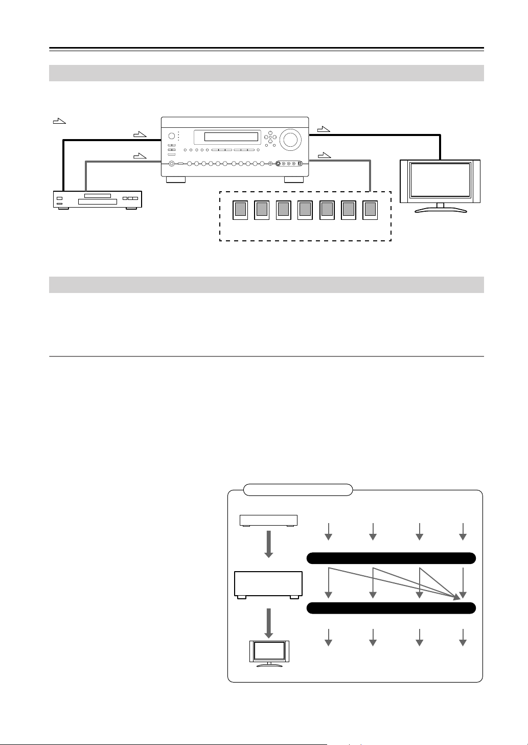
30
Connecting Your Components
—Continued
By connecting both the audio and video outputs of your DVD player and other AV components to the AV receiver, you
can switch the audio and video signals simultaneously simply by changing the input source on the AV receiver.
The AV receiver supports several connection formats for compatibility with a wide range of AV equipment. The format
you choose will depend on the formats supported by your other components. Use the following sections as a guide.
For video components, you must make an audio connection and a video connection.
Video Connection Formats
Video equipment can be connected to the AV receiver by using any one of the following video connection formats:
composite video, S-Video, component video, or HDMI, the latter offering the best picture quality.
The AV receiver can upconvert and downconvert between video formats, depending on the HDMI Monitor setting,
which generally determines whether video signals are upconverted for the component video output or the HDMI output.
For optimal video performance, THX recommends that video signals pass through the system without upconver-
sion (e.g., component video input through to component video output). It’s also recommended that you set the
Immediate Display preference to Off (page 112).
■
HDMI Monitor Setting Set to Main or Sub
With the HDMI Monitor setting set to Main or
Sub (see page 48), video input signals flow
through the AV receiver as shown, with com-
posite video, S-Video, and component video
sources all being upconverted for the HDMI
output.
Use the Main or Sub setting if you
connect the AV receiver’s HDMI OUT
MAIN or HDMI OUT SUB, respectively, to
your TV.
The composite video, S-Video, and component
video outputs pass through their respective
input signals as they are.
Connecting Audio and Video Signals to the AV Receiver
: Signal Flow
Video
Video
Audio
Speakers (see page 23 for hookup details)
DVD player, etc.
TV, projector,
etc.
Audio
Which Connections Should I Use?
IN
MONITOR OUT
DVD player, etc.
AV receiver
TV, projector, etc.
Composite S-Video Component
Video Signal Flow Chart
HDMI
Composite S-Video Component
HDMI
Loading...