


 Loading...
AV Receiver
DTR-5.9
Instruction Manual
Thank you for purchasing an Integra AV Receiver. Please read this manual thoroughly before making connections and plugging in the unit. Following the instructions in this manual will enable you to obtain optimum performance and listening enjoyment from your new AV Receiver.
Please retain this manual for future reference.
WARNING:
TO REDUCE THE RISK OF FIRE OR ELECTRIC SHOCK, DO NOT EXPOSE THIS APPARATUS TO RAIN OR MOISTURE.
CAUTION:
TO REDUCE THE RISK OF ELECTRIC SHOCK, DO NOT REMOVE COVER (OR BACK). NO USER-SERVICEABLE PARTS INSIDE. REFER SERVICING TO QUALIFIED SERVICE PERSONNEL.
WARNING |
|
AVIS |
RISK OF ELECTRIC SHOCK |
|
RISQUE DE CHOC ELECTRIQUE |
DO NOT OPEN |
|
NE PAS OUVRIR |
The lightning flash with arrowhead symbol, within an equilateral triangle, is intended to alert the user to the presence of uninsulated “dangerous voltage” within the product’s enclosure that may be of sufficient
magnitude to constitute a risk of electric shock to persons.
The exclamation point within an equilateral triangle is intended to alert the user to the presence of important operating and maintenance (servicing) instructions in the literature accompanying the appliance.
Important Safety Instructions
1.Read these instructions.
2.Keep these instructions.
3.Heed all warnings.
4.Follow all instructions.
5.Do not use this apparatus near water.
6.Clean only with dry cloth.
7.Do not block any ventilation openings. Install in accordance with the manufacturer’s instructions.
8.Do not install near any heat sources such as radiators, heat registers, stoves, or other apparatus (including amplifiers) that produce heat.
9.Do not defeat the safety purpose of the polarized or grounding-type plug. A polarized plug has two blades with one wider than the other. A grounding type plug has two blades and a third grounding prong. The wide blade or the third prong are provided for your safety. If the provided plug does not fit into your outlet, consult an electrician for replacement of the obsolete outlet.
10.Protect the power cord from being walked on or pinched particularly at plugs, convenience receptacles, and the point where they exit from the apparatus.
11.Only use attachments/accessories specified by the manufacturer.
12. Use only with the cart, stand, tripod, bracket, or table specified by the manufacturer, or sold with the apparatus. When a cart is used, use caution when moving the cart/ apparatus combination to avoid injury from tip-over.
13.Unplug this apparatus during lightning storms or when unused for long periods of time.
14.Refer all servicing to qualified service personnel. Servicing is required when the apparatus has been damaged in any way, such as power-supply cord or
|
plug is damaged, liquid has been spilled or objects |
|
have fallen into the apparatus, the apparatus has |
|
been exposed to rain or moisture, does not operate |
2 |
normally, or has been dropped. |
|
15.Damage Requiring Service
Unplug the apparatus from the wall outlet and refer servicing to qualified service personnel under the following conditions:
A.When the power-supply cord or plug is damaged,
B.If liquid has been spilled, or objects have fallen into the apparatus,
C.If the apparatus has been exposed to rain or water,
D.If the apparatus does not operate normally by following the operating instructions. Adjust only those controls that are covered by the operating instructions as an improper adjustment of other controls may result in damage and will often require extensive work by a qualified technician to restore the apparatus to its normal operation,
E.If the apparatus has been dropped or damaged in any way, and
F.When the apparatus exhibits a distinct change in performance this indicates a need for service.
16.Object and Liquid Entry
Never push objects of any kind into the apparatus through openings as they may touch dangerous voltage points or short-out parts that could result in a fire or electric shock.
The apparatus shall not be exposed to dripping or splashing and no objects filled with liquids, such as vases shall be placed on the apparatus.
Don’t put candles or other burning objects on top of this unit.
17.Batteries
Always consider the environmental issues and follow local regulations when disposing of batteries.
18.If you install the apparatus in a built-in installation, such as a bookcase or rack, ensure that there is adequate ventilation.
Leave 20 cm (8") of free space at the top and sides and 10 cm (4") at the rear. The rear edge of the shelf or board above the apparatus shall be set 10 cm (4") away from the rear panel or wall, creating a flue-like gap for warm air to escape.

Precautions
1.Recording Copyright—Unless it’s for personal use only, recording copyrighted material is illegal without the permission of the copyright holder.
2.AC Fuse—The AC fuse inside the unit is not userserviceable. If you cannot turn on the unit, contact the dealer.
3.Care—Occasionally you should dust the unit all over with a soft cloth. For stubborn stains, use a soft cloth dampened with a weak solution of mild detergent and water. Dry the unit immediately afterwards with a clean cloth. Don’t use abrasive cloths, thinners, alcohol, or other chemical solvents, because they may damage the finish or remove the panel lettering.
4.Power WARNING
BEFORE PLUGGING IN THE UNIT FOR THE FIRST TIME, READ THE FOLLOWING SECTION CAREFULLY.
AC outlet voltages vary from country to country. Make sure that the voltage in your area meets the voltage requirements printed on the unit’s rear panel (e.g., AC 230 V, 50 Hz or AC 120 V, 60 Hz).
The power cord plug is used to disconnect this unit from the AC power source. Make sure that the plug is readily operable (easily accessible) at all times.
Pressing the [On/Standby] button to select Standby mode does not fully shutdown the unit. If you do not intend to use the unit for an extended period, remove the power cord from the AC outlet.
5.Never Touch this Unit with Wet Hands—Never handle this unit or its power cord while your hands are wet or damp. If water or any other liquid gets inside this unit, have it checked by the dealer.
6.Handling Notes
•If you need to transport this unit, use the original packaging to pack it how it was when you originally bought it.
•Do not leave rubber or plastic items on this unit for a long time, because they may leave marks on the case.
•This unit’s top and rear panels may get warm after prolonged use. This is normal.
•If you do not use this unit for a long time, it may not work properly the next time you turn it on, so be sure to use it occasionally.
For U.S. models
FCC Information for User
CAUTION:
The user changes or modifications not expressly approved by the party responsible for compliance could void the user’s authority to operate the equipment.
NOTE:
This equipment has been tested and found to comply with the limits for a Class B digital device, pursuant to Part 15 of the FCC Rules. These limits are designed to provide reasonable protection against harmful interference in a residential installation.
This equipment generates, uses and can radiate radio frequency energy and, if not installed and used in accordance with the instructions, may cause harmful interference to radio communications. However, there is no guarantee that interference will not occur in a particular installation. If this equipment does cause harmful interference to radio or television reception, which can be determined by turning the equipment off and on, the user is encouraged to try to correct the interference by one or more of the following measures:
•Reorient or relocate the receiving antenna.
•Increase the separation between the equipment and receiver.
•Connect the equipment into an outlet on a circuit different from that to which the receiver is connected.
•Consult the dealer or an experienced radio/TV technician for help.
For Canadian Models
NOTE: THIS CLASS B DIGITAL APPARATUS COMPLIES WITH CANADIAN ICES-003.
For models having a power cord with a polarized plug: CAUTION: TO PREVENT ELECTRIC SHOCK, MATCH WIDE BLADE OF PLUG TO WIDE SLOT, FULLY INSERT.
Pour les Modèles Canadiens
REMARQUE: CET APPAREIL NUMÉRIQUE DE LA CLASSE B EST CONFORME À LA NORME NMB-003 DU CANADA.
Sur les modèles dont la fiche est polarisée: ATTENTION: POUR ÉVITER LES CHOCS ÉLECTRIQUES, INTRODUIRE LA LAME LA PLUS LARGE DE LA FICHE DANS LA BORNE CORRESPONDANTE DE LA PRISE ET POUSSER JUSQU’AU FOND.
3
Supplied Accessories
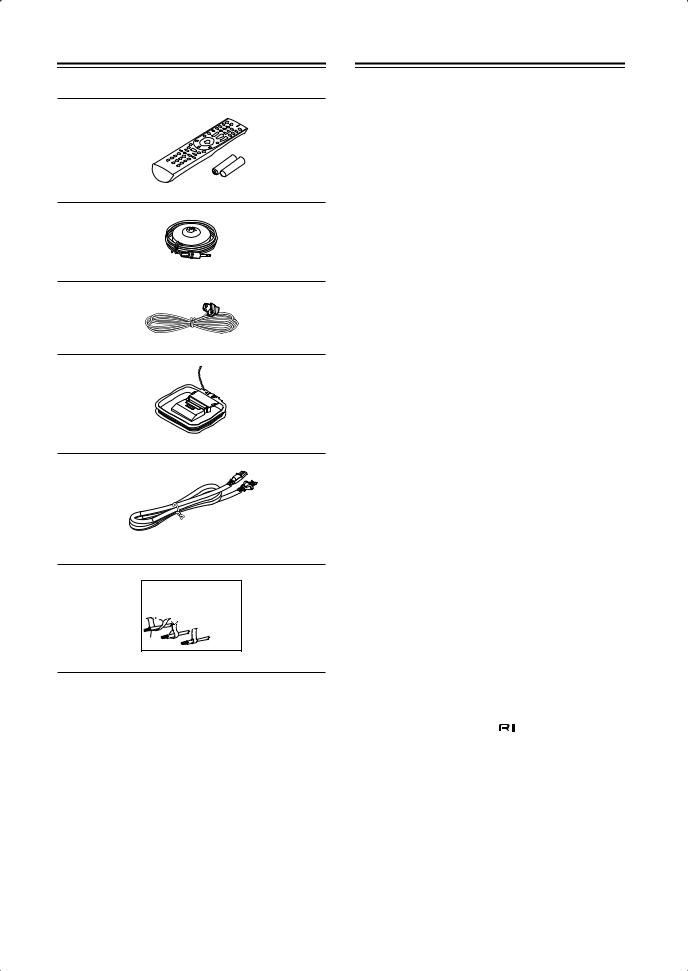
Make sure you have the following accessories:
Remote controller and two batteries (AA/R6)
Speaker setup microphone
Indoor FM antenna
AM loop antenna
Power cord
(Power cord varies from country to country.)
Front |
Left |
Front |
Left |
SP-B /Zone2 |
Left |
SP-B /Zone2 |
Left |
Front |
Right |
Front |
Right |
SP-B /Zone2 |
Right |
SP-B /Zone2 |
Right |
Surround |
Left |
Surround |
Left |
Surround |
Right |
Surround |
Right |
Center |
Center |
SurroundBack |
Left |
SurroundBack |
Left |
Zone2 |
Left |
Zone2 |
Left |
SurroundBack |
Right |
SurroundBack |
Right |
Zone2 |
Right |
Zone2 |
Right |
Front |
Left |
Front |
Left |
SP-B / Zone 2 |
Left |
SP-B / Zone 2 |
Left |
Front |
Right |
Front |
Right |
SP-B / Zone 2 |
Right |
SP-B / Zone 2 |
Right |
Surround |
Left |
Surround |
Left |
Surround |
Right |
Surround |
Right |
Center |
Center |
Surround Back |
Left |
Surround Back |
Left |
Zone 2 |
Left |
Zone 2 |
Left |
Surround Back |
Right |
Surround Back |
Right |
Zone 2 |
Right |
Zone 2 |
Right |
1
2
3
Speaker Cable
Speaker cable labels
*In catalogs and on packaging, the letter at the end of the product name indicates the color. Specifications and operation are the same regardless of color.
Contents |
|
|
Important Safety Instructions........................... |
2 |
|
Supplied Accessories ...................................... |
|
4 |
Features ............................................................. |
|
6 |
Multiroom Capability ........................................ |
|
7 |
Getting to Know the AV Receiver .................... |
8 |
|
Front Panel .............................................................. |
|
8 |
Display .................................................................... |
|
9 |
Rear Panel ............................................................. |
|
10 |
Remote Controller .......................................... |
|
12 |
Controlling the AV Receiver ................................ |
|
12 |
Installing the Batteries .......................................... |
|
13 |
Using the Remote Controller ................................ |
|
13 |
Connecting Your Speakers ............................ |
|
14 |
Enjoying Home Theater ....................................... |
|
14 |
Bi-amping Front Speakers .................................... |
|
18 |
Connecting Antennas ..................................... |
|
19 |
Connecting the Indoor FM Antenna ..................... |
19 |
|
Connecting the AM Loop Antenna ...................... |
19 |
|
Connecting an Outdoor FM Antenna ................... |
20 |
|
Connecting an Outdoor AM Antenna ................... |
20 |
|
Connecting Your Components ...................... |
21 |
|
About AV Connections ........................................ |
|
21 |
Connecting Audio and Video Signals |
|
|
to the AV Receiver ............................................. |
|
22 |
Which Connections Should I Use? ....................... |
22 |
|
Connecting a TV or Projector ............................... |
|
24 |
Connecting a DVD player .................................... |
|
25 |
Connecting a VCR or DVR for Playback ............. |
27 |
|
Connecting a VCR or DVR for Recording ........... |
28 |
|
Connecting a Satellite, Cable, Terrestrial Set-top |
|
|
box, or Other Video Source ............................... |
|
29 |
Connecting a Game Console ................................ |
|
30 |
Connecting Components with HDMI ................... |
31 |
|
Making HDMI Connections ................................. |
|
32 |
Connecting a Camcorder or Other Device ........... |
33 |
|
Connecting a Power Amplifier ............................. |
|
33 |
Connecting a CD Player or Turntable .................. |
34 |
|
Connecting a Cassette, CDR, MiniDisc, or |
|
|
DAT Recorder .................................................... |
|
35 |
Connecting an RI Dock ........................................ |
|
36 |
Connecting Integra/Onkyo |
Components ....... |
37 |
Turning On the AV Receiver .......................... |
|
38 |
Connecting the Power Cord .................................. |
|
38 |
Turning On and Standby ...................................... |
|
38 |
First Time Setup .............................................. |
|
39 |
Automatic Speaker Setup ..................................... |
|
39 |
Speaker Settings ................................................... |
|
43 |
HDMI Input Setup ................................................ |
|
44 |
Component Video Input Setup ............................. |
|
45 |
Digital Input Setup ............................................... |
|
45 |
Changing the Input Display .................................. |
|
46 |
Automatic Audio Input Selection Setup ............... |
47 |
|
4

Contents—Continued
Playing Your AV Components ...................... |
48 |
Basic AV Receiver Operation ............................... |
48 |
Common Functions ........................................ |
49 |
Setting the Display Brightness .............................. |
49 |
Muting the AV Receiver ....................................... |
49 |
Using the Sleep Timer ........................................... |
49 |
Using Headphones ................................................ |
50 |
Displaying Source Information ............................. |
50 |
Specifying the Digital Signal Format .................... |
51 |
Listening to the Radio .................................... |
52 |
AM Frequency Step Setup |
|
(on some models) ................................................ |
52 |
Listening to AM/FM Stations ............................... |
53 |
Presetting AM/FM Stations ................................... |
55 |
Listening to SIRIUS Satellite Radio® |
|
(North American Models Only) .......................... |
56 |
Using RDS (European models only) ..................... |
65 |
Using the Listening Modes ............................ |
67 |
Selecting the Listening Modes .............................. |
67 |
Listening Modes Available for Each Source |
|
Format ................................................................. |
68 |
About the Listening Modes ................................... |
74 |
Recording ........................................................ |
76 |
Recording the Input Source ................................... |
76 |
Recording from Different AV Sources ................. |
76 |
Adjusting the Listening Modes ..................... |
77 |
Using the Audio Adjust Settings ........................... |
77 |
Using the Audio Settings ...................................... |
79 |
Listening Mode Presets ......................................... |
81 |
Advanced Setup ............................................. |
82 |
Speaker Setup ........................................................ |
82 |
Source Setup .......................................................... |
87 |
Miscellaneous Setup .............................................. |
88 |
Hardware Setup ..................................................... |
89 |
Lock Setup ............................................................ |
92 |
Zone 2 .............................................................. |
93 |
Connecting Zone 2 ................................................ |
93 |
Powered Zone 2 Setting ........................................ |
94 |
Zone 2 Out Settings ............................................... |
95 |
Using Zone 2 ......................................................... |
96 |
Using the 12V Triggers ......................................... |
98 |
Using the Remote Controller in Zone 2 and |
|
Multiroom Control Kits ...................................... |
99 |
Controlling Other Components ................... |
100 |
Preprogrammed Remote Control Codes ............. |
100 |
Entering Remote Control Codes ......................... |
100 |
Resetting the Remote Controller ......................... |
101 |
Controlling a TV ................................................. |
102 |
Controlling a DVD Player, or DVD Recorder .... |
103 |
Controlling a VCR or DVR ................................. |
104 |
Controlling a Satellite Receiver or Cable |
|
Receiver ............................................................ |
105 |
Controlling a CD Player, CD Recorder, |
|
or MD Player .................................................... |
106 |
Controlling an RI Dock ...................................... |
107 |
Controlling a Cassette Recorder ......................... |
108 |
Troubleshooting ........................................... |
109 |
Specifications ............................................... |
113 |
Video Resolution Chart ................................ |
114 |
Onscreen Setup Menus ................................ |
115 |
*To reset the AV receiver to its factory defaults, turn it on and, while holding down the [VCR/DVR] button, press the [On/Standby] button (see page 109).
5
Features
Amplifier
•7-channel amplifier
•90 Watts/Channel @ 8 ohms (FTC)
•WRAT-Wide Range Amplifier Technology (5Hz–100kHz bandwidth)
•Optimum Gain Volume Circuitry
Processing
•HDMI Video Upscaling (Up to 1080i)
•HDMI Video Upconversion
•Dolby TrueHD*1
•DTS-HD Master Audio*2
•Faroudja DCDi Edge Enhancement
•Direct Mode
•Music Optimizer*3 for Compressed Music
•CinemaFILTER
•Non-Scaling Configuration
•A-Form Listening Mode Memory
•24-bit/192kHz D/A Converters
•Powerful and Highly Accurate 32-bit DSP Processing
Connections
•4 HDMI*4 Inputs and 1 Output
•Integra RIHD for System Control
•HDTV-Ready Component Video Switching (2 Inputs/1 Output)
•4 Digital Inputs (2 Optical/2 Coaxial/4 Assignable),
1 Digital Output (Optical)
•4 S-Video Inputs/2 Outputs
•Powered Zone 2
•Color-Coded 7.1 Multichannel Inputs
•Bi-Amp Connectable for Front L/R with Surround Back L/R
Miscellaneous
•40 Sirius*5/AM/FM Presets (North American model)
•40 AM/FM Presets (Other models)
•Audyssey 2EQ*6 Room Correction and Speaker Calibration
•Audyssey Dynamic EQ*6 Loudness Correction
•Crossover Adjustment (40/45/50/55/60/70/80/90/100/110/120/130/150/ 200Hz)
•A/V Sync Control Function (up to 100 ms)
•On-Screen Display
•Compatible with RI Dock for iPod
•Aluminum Front Panel
•Preprogrammed 
 -Compatible Remote
*1.
Manufactured under license from Dolby Laboratories. Dolby, Pro Logic, and the double-D symbol are trademarks of Dolby Laboratories.
*2.
Manufactured under license under U.S. Patent #’s: 5,451,942; 5,956,674; 5,974,380; 5,978,762; 6,226,616; 6,487,535 & other U.S. and worldwide patents issued & pending. DTS is a registered trademark and the DTS logos, Symbol, DTS-HD and DTS-HD Master Audio are trademarks of DTS, Inc.
“DTS” and “DTS-ES | Neo: 6” are registered trademarks of DTS, Inc. “96/24” is a trademark of DTS, Inc.
*3 Music Optimizer™ is a trademark of Onkyo Corporation.
*4
HDMI, the HDMI logo and High Definition Multimedia Interface are trademarks or registered trademarks of HDMI Licensing, LLC.
*5
©2005 SIRIUS Satellite Radio Inc. “SIRIUS,” SiriusConnect, the SIRIUS dog logo, channel names and logos are trademarks of SIRIUS Satellite Radio Inc. Available only in the contiguous United States (excluding Alaska and Hawaii) and Canada.
*6
Manufactured under license from Audyssey Laboratories. U.S. and foreign patents pending. Audyssey 2EQ and Dynamic EQ are trademarks of Audyssey Laboratories.
*Apple and iPod are trademarks of Apple Computer, Inc., registered in the U.S. and other countries.
*“x.v.Color” is a trademark of Sony Corporation.
This product incorporates copyright protection technology that is protected by U.S. patents and other intellectual property rights. Use of this copyright protection technology must be authorized by Macrovision Corporation, and is intended for home and other limited consumer uses only unless otherwise authorized by Macrovision. Reverse engineering or disassembly is prohibited.
6
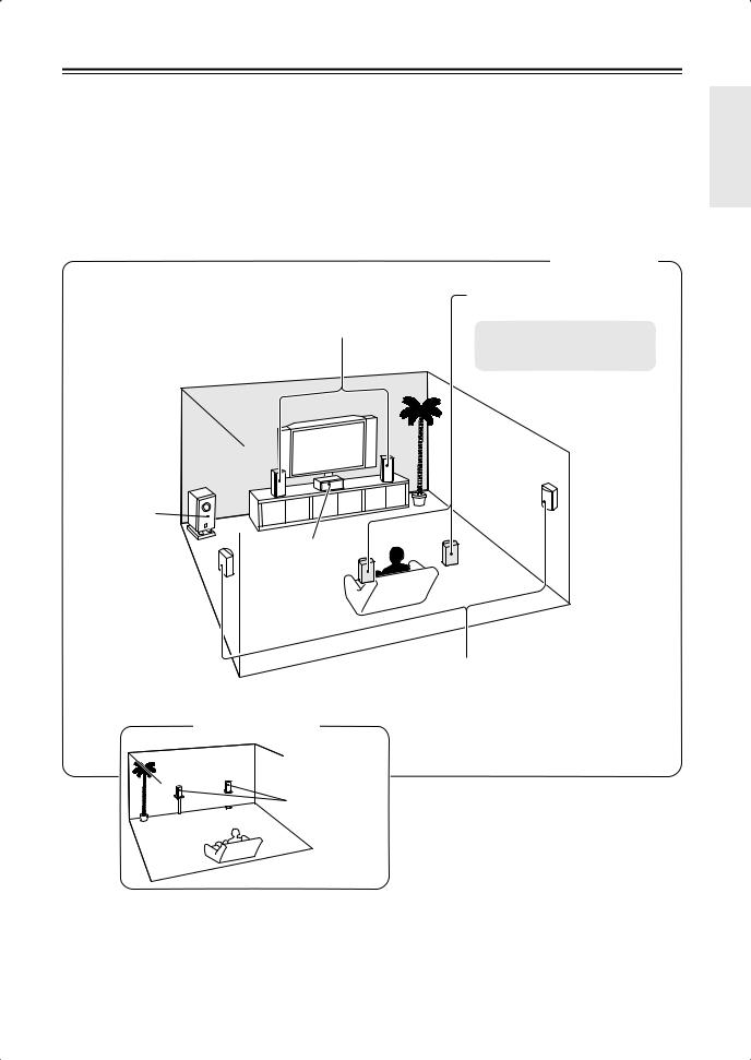
Multiroom Capability
You can use two speaker systems with this AV receiver—a surround-sound speaker system (up to 7.1 channels) in your main listening room, a stereo speaker system in a second room, or Zone 2, as we call it. And, you can select a different audio source for each room.
Main Room: In your main listening room, you can enjoy up to 7.1-channel playback (see page 14). You can enjoy the various listening modes such as Dolby and DTS (pages 67–75).
*While Powered Zone 2 is being used, playback is reduced to 5.1-channels (see page 93).
Zone 2: In your Zone 2 room, you can enjoy 2-channel stereo playback (see page 93). *The listening modes cannot be used with Zone 2.
Main Room
|
Surround back left and right |
|
speakers |
Front left and right speakers |
* While Powered Zone 2 is being |
|
|
|
used, nothing is output by these |
|
speakers (page 94). |
Subwoofer
Center speaker
Surround left and right speakers
Zone 2 Room
 Left and right
  stereo speakers
7
Getting to Know the AV Receiver
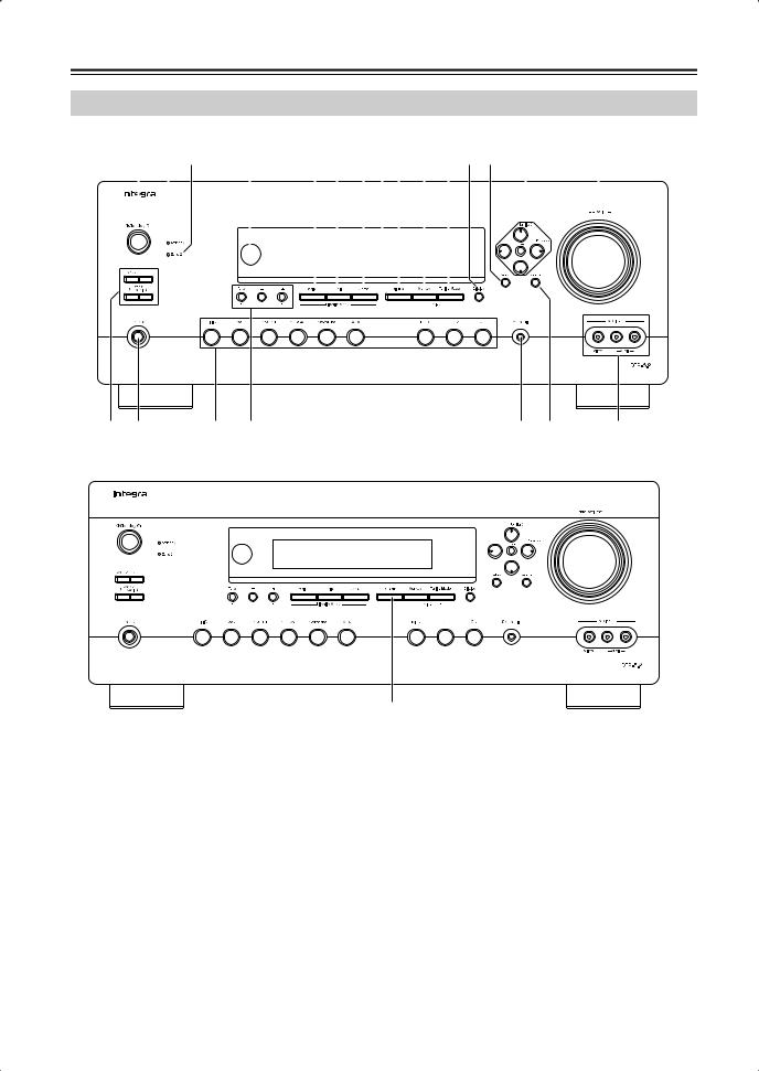
Front Panel
North American model
|
1 2 3 4 5 6 789 J K L M N |
O |
||||||||||||||
|
|
|
|
|
|
|
|
|
|
|
|
|
|
|
|
|
|
|
|
|
|
|
|
|
|
|
|
|
|
|
|
|
|
|
|
|
|
|
|
|
|
|
|
|
|
|
|
|
|
|
|
|
|
|
|
|
|
|
|
|
|
|
|
|
|
|
|
|
|
|
|
|
|
|
|
|
|
|
|
|
|
|
|
|
|
|
|
|
|
|
|
|
|
|
|
|
|
|
|
|
|
|
|
|
|
|
|
|
|
|
|
|
|
|
|
|
|
|
|
|
|
|
|
|
|
|
|
|
|
|
|
|
|
|
|
|
|
|
|
|
|
|
|
|
|
|
|
|
|
|
|
|
P Q |
R S |
T U |
V |
Other models
9
The actual front panel has various logos printed on it. They are not shown here for clarity.
The page numbers in parentheses show where you can find the main explanation for each item.
AOn/Standby button (38)
Sets the AV receiver to On or Standby.
BStandby indicator (38)
Lights up when the AV receiver is on Standby and flashes while a signal is being received from the remote controller.
CZone 2 indicator (96)
Flashes when Zone 2 is being set. Lights up when Zone 2 is on.
DRemote-control sensor (13)
Receives control signals from the remote controller.
EMovie/TV button (67)
Selects the listening modes intended for use with movies and TV.
FMusic button (67)
Selects the listening modes intended for use with music.
GGame button (67)
Selects the listening modes intended for use with video games.
HDisplay
See “Display” on page 9.
IDimmer (RT/PTY/TP) button (49, 66)
Adjusts the display brightness.
On the European models, this is the RT/PTY/TP button, and it’s used with RDS (Radio Data System). See “Using RDS (European models only)” on page 65.
8
Getting to Know the AV Receiver—Continued
JMemory button (55)
Used when storing or deleting radio presets.
KTuning Mode button (53)
Selects the Auto or Manual tuning mode for AM and FM radio.
LDisplay button (50)
Displays various information about the currently selected input source.
MSetup button
Opens and closes the onscreen setup menus, which are displayed on the connected TV.
NTuning, Preset, Arrow, and Enter buttons
When AM or FM is selected, the Tuning [ ] [
] [ ] buttons are used for radio tuning, and the Preset
[ ] [
] [ ] buttons are used to select radio presets (see page 55). With the onscreen setup menus, they work as arrow buttons and are used to select and set items. The Enter button is also used with the onscreen setup menus.
OMaster Volume control (48)
Sets the volume of the AV receiver to Min, 1 through, or Max.
The maximum volume level can be limited with the Maximum Volume setting. See “Volume Setup” on page 88.
PZone 2, Level [ ]/[
]/[ ], and Off buttons (96)
The Zone 2 button is used when setting Zone 2.
The Level Up and Down [ ]/[
]/[ ] buttons are used when adjusting the volume level of Zone 2.
The Off button is used to turn off Zone 2.
QPhones jack (50)
This 1/4-inch phone jack is for connecting a standard pair of stereo headphones for private listening.
RInput selector buttons (48)
Select the following input sources: DVD, VCR/DVR, CBL/SAT, Game/TV, AUX, Tape, Tuner, CD.
The [Multi CH] button selects the multichannel DVD input.
STone, Plus [+], and Minus [–] buttons (79, 97)
Used to adjust the tone (bass and treble), and the volume and balance of Zone 2.
TSetup Mic (39)
The automatic speaker setup microphone connects here.
UReturn button
Selects the previously displayed setup menu.
VAUX Input (33, 76)
Used to connect a camcorder, game console, and so on. There are input jacks for composite video and analog audio.
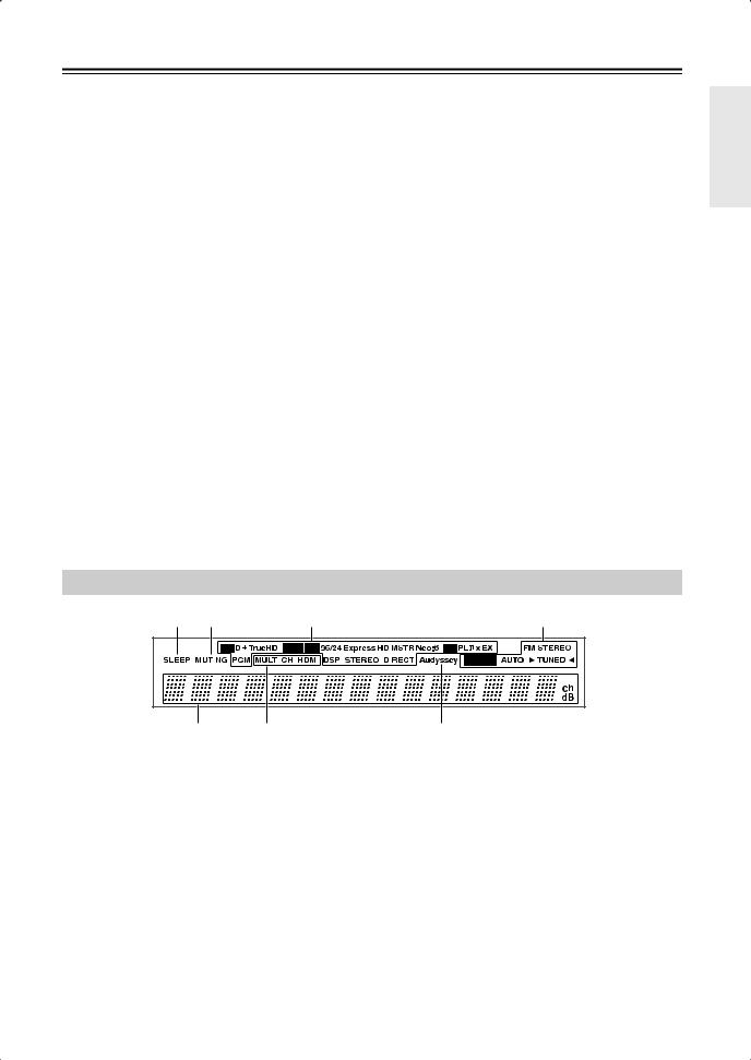
Display
1 2 |
3 |
4 |
||
|
|
|
|
|
|
|
|
|
|
56
For detailed information, see the pages in parentheses.
1SLEEP indicator (49)
Lights up when the Sleep function has been set.
2MUTING indicator (49)
Flashes while the AV receiver is muted.
3Listening mode and format indicators (51, 67)
Show the selected listening mode and audio input signal format.
4Tuning indicators (53)
FM STEREO (53): Lights up when tuned to a stereo FM station.
RDS (65): Lights up when tuned to a radio station that supports RDS (Radio Data System).
7
AUTO (53): Lights up when Auto Tuning mode is selected for AM or FM radio. Goes off when Manual Tuning mode is selected.
TUNED (53): Lights up when tuned to a radio station.
5Message area
Displays various information.
6Audio input indicators
Indicate the type of audio input that’s selected as the audio source: MULTI CH, or HDMI.
7Audyssey indicator
Flashes during automatic speaker setup.
9

Getting to Know the AV Receiver—Continued
Rear Panel
North American model 7Only North American model
1 2 3 4 56 89 J K L M N
SIRIUS |
AM |
ANTENNA
FM 75
O P Q R ST UV W |
X |
Y |
Z |
Other models
1 2 3 4 5 6 89 J K L M N
AM |
ANTENNA
FM 75
O P Q R ST UV W
ADIGITAL IN COAXIAL 1 and 2
These coaxial digital audio inputs are for connecting components with a coaxial digital audio output, such as a CD player or DVD player. They’re assignable, which means you can assign each one to an input selector to suit your setup. See “Digital Input Setup” on page 45.
BCOMPONENT VIDEO IN 1 and 2
These RCA component video inputs are for connecting components with a component video output, such as a DVD player, DVD recorder, or DVR (digital video recorder). They’re assignable, which
|
means you can assign each one to an input selector |
|
to suit your setup. See “Component Video Input |
10 |
Setup” on page 45. |
|
X Y Z
CCOMPONENT VIDEO OUT
This RCA component video output is for connecting a TV or projector with a component video input.
DHDMI IN 1–4 and OUT
HDMI (High Definition Multimedia Interface) connections carry digital audio and digital video.
The HDMI inputs are for connecting components with an HDMI output, such as a DVD player, DVD recorder, or DVR (digital video recorder). They’re assignable, which means you can assign each one to an input selector to suit your setup. See “HDMI Input Setup” on page 44.
The HDMI outputs are for connecting a TV or projector with an HDMI input.
Getting to Know the AV Receiver—Continued
EETHERNET
This port is for connecting the AV receiver to home automation equipment and external controllers. Use only shielded Ethernet cables.
FMONITOR OUT
The S-Video or composite video jack should be connected to a video input on your TV or projector.
GSIRIUS antenna (on North American model)
This jack is for connecting a SIRIUS digital antenna, sold separately (see the separate SIRIUS instructions).
HFM ANTENNA
This jack is for connecting an FM antenna.
IAM ANTENNA
These push terminals are for connecting an AM antenna.
JIR IN A/B and OUT
A commercially available IR receiver can be connected to the IR IN A or B jack, allowing you to control the AV receiver while you’re in Zone 2, or control it when it’s out of sight, for example, installed in a cabinet.
A commercially available IR emitter can be connected to the IR OUT jack to pass IR (infrared) remote control signals through to other components.
K12V TRIGGER OUT (A/B/C)
These outputs can be connected to the 12-volt trigger inputs on other components.
LRS232
This port is for connecting the AV receiver to home automation equipment and external controllers.
MZONE 2 PRE OUT L/R
These analog audio outputs can be connected to the line inputs on amplifiers in Zone 2.
NZONE 2 SPEAKERS L/R
These terminal posts are for connecting speakers in Zone 2.
ODIGITAL OPTICAL IN 1, 2, and OUT
These optical digital audio inputs are for connecting components with an optical digital audio output, such as a CD player or DVD player. They’re assignable, which means you can assign each one to an input selector to suit your setup. See “Digital Input Setup” on page 45.
The optical digital audio output is for connecting a digital recorder with an optical digital input, such as a CD recorder.
P
 REMOTE CONTROL
This 
 (Remote Interactive) jack can be connected to the
 jack on another
 -capable Integra/ Onkyo component for remote and system control.
To use 
 , you must make an analog audio connection (RCA) between the AV receiver and the other component, even if they are connected digitally.
QCD IN
This analog audio input is for connecting a CD player’s analog audio output.
RTAPE IN/OUT
These analog audio input and output jacks are for connecting a recorder with an analog audio input and output, such as a cassette deck, MD recorder, etc.
SGAME/TV IN
A game console or TV output can be connected here. There’s S-Video and composite video input jacks for connecting the video signal.
TCBL/SAT IN
A cable or satellite receiver can be connected here. There are S-Video and composite video input jacks for connecting the video signal, and there are analog audio input jacks for connecting the audio signal.
UVCR/DVR IN/OUT
A video component, such as a VCR or DVR, can be connected here for recording and playback. There are S-Video and composite video input and output jacks for connecting the video signal, and there are analog audio input jacks for connecting the audio signal.
VDVD IN
This input is for connecting a DVD player. There are S-Video and composite video input jacks for connecting the video signal.
WDVD FRONT L/R, CENTER, SUBWOOFER, SURR L/R, and SURR BACK L/R
This analog multichannel input is for connecting a component with a 5.1/7.1-channel analog audio output, such as a DVD player, DVD-Audio or SACD-capable player, or an MPEG decoder.
XPRE OUT: FRONT L/R, CENTER, SUBWOOFER, SURR L/R, and SURR BACK L/R
This 5.1/7.1 multichannel analog audio output can be connected to the analog audio input on a multichannel power amplifier for when you want to use the AV receiver solely as a preamplifier. The SUBWOOFER jack is for connecting a powered subwoofer.
YFRONT L/R, CENTER, SURR L/R, and SURR BACK L/R SPEAKERS
These terminal posts are for connecting the front speakers, center, surround, and surround back speakers.
ZAC INLET
The supplied power cord is connected here. The other end of the power cord should be connected to a suitable wall outlet.
See pages 14–37 for hookup information.
11
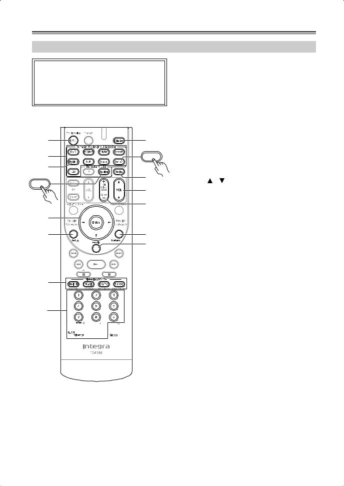
Remote Controller
Controlling the AV Receiver
To control the AV receiver, press the [Receiver] Remote Mode button to select Receiver mode. You can also use the remote controller to control your DVD player, CD player, and other components. See page 100 for more details.
CMulti CH button (48)
Selects the multichannel DVD input.
DArrow [ ]/[
]/[ ]/[
]/[ ]/[
]/[ ] and Enter buttons
Used to select and adjust settings.
ESetup button
Used to change settings.
FListening Mode buttons (67)
Used to select the listening modes.
GDimmer button (49)
A |
84 |
Adjusts the display brightness. |
|||
H Display button (50) |
|||||
|
|
||||
2 |
Tuner |
Displays information about the current input source. |
|||
I Muting button (49) |
|||||
3 |
|
||||
|
Mutes or unmutes the AV receiver. |
||||
|
9 |
||||
|
J VOL [ |
]/[ |
] button (48) |
||
Receiver |
|
||||
J
5
14 *


5 |
K |
L
6
2
37


 M
M
For detailed information, see the pages in parentheses.
AOn/Standby button (38)
Sets the AV receiver to On or Standby.
BRemote Mode/Input Selector buttons (48, 102–108)
Selects the remote controller modes and the input sources.
Adjusts the volume of the AV receiver regardless of the currently selected remote controller mode.
KReturn button
Returns to the previous display when changing settings.
LAudio button (79)
Used to change audio settings.
When the Audio TV Out setting is set to On (page 91), this button is disabled.
MSleep button (49)
Used with the Sleep function.
* SP A/B is not used in this AV receiver.
■ Controlling the tuner
To control the AV receiver’s tuner, press the [Tuner] (or [Receiver]) Remote Mode button.
You can select AM or FM by pressing the [Tuner] button repeatedly.
1Arrow [ ]/[
]/[ ] buttons
Used to tune into radio stations.
2Number buttons (54)
Used to select AM and FM radio stations directly.
3D.TUN button (54)
Selects the Direct tuning mode.
4Display button (54)
Displays information about the band, frequency, preset number, and so on.
5CH +/– button (55)
Selects radio presets.
Note:
•An Onkyo cassette recorder connected via 
 can also be controlled in Receiver mode (see page 108).
12
Remote Controller—Continued
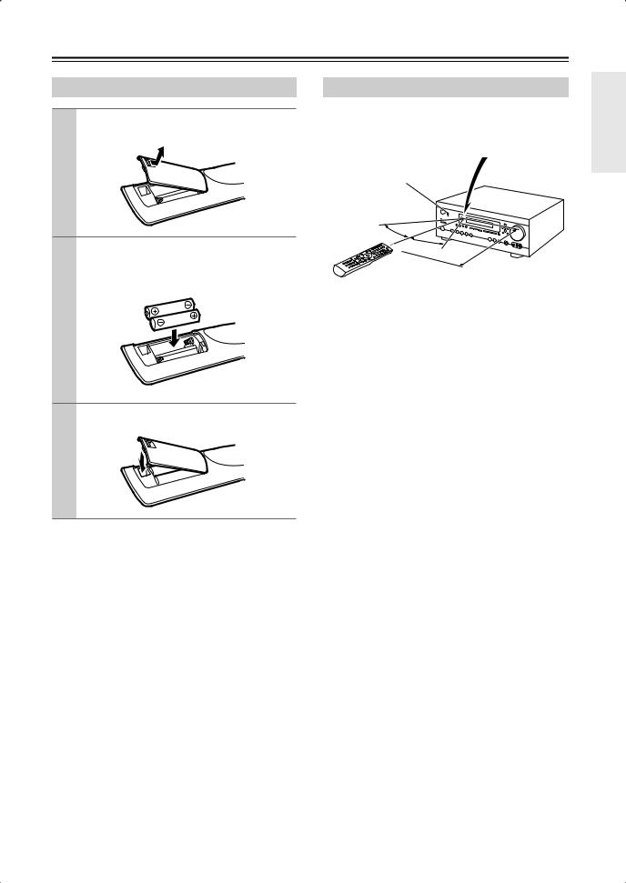
Installing the Batteries
1 To open the battery compartment, press the small lever and remove the cover.
2 Insert the two supplied batteries (AA/R6) in accordance with the polarity diagram inside the battery compartment.
3 Replace the cover and push it shut.
Notes:
•If the remote controller doesn’t work reliably, try replacing the batteries.
•Don’t mix new and old batteries or different types of batteries.
•If you intend not to use the remote controller for a long time, remove the batteries to prevent damage from leakage or corrosion.
•Expired batteries should be removed as soon as possible to prevent damage from leakage or corrosion.
Using the Remote Controller
When using the remote controller, point it toward the AV receiver’s remote control sensor, as shown below.
Remote control sensor
Standby indicator |
AV receiver |
30˚
30˚
Approx. 16 ft. (5 m)
Notes:
•The remote controller may not work reliably if the AV receiver is subjected to bright light, such as direct sunlight or inverter-type fluorescent lights. Keep this in mind when installing.
•If another remote controller of the same type is used in the same room, or the AV receiver is installed close to equipment that uses infrared rays, the remote controller may not work reliably.
•Don’t put anything on top of the remote controller, such as a book or magazine, because a button may be pressed continuously, thereby draining the batteries.
•The remote controller may not work reliably if the AV receiver is installed in a rack behind colored glass doors. Keep this in mind when installing.
•The remote controller will not work if there’s an obstacle between it and the AV receiver’s remote control sensor.
13
Connecting Your Speakers
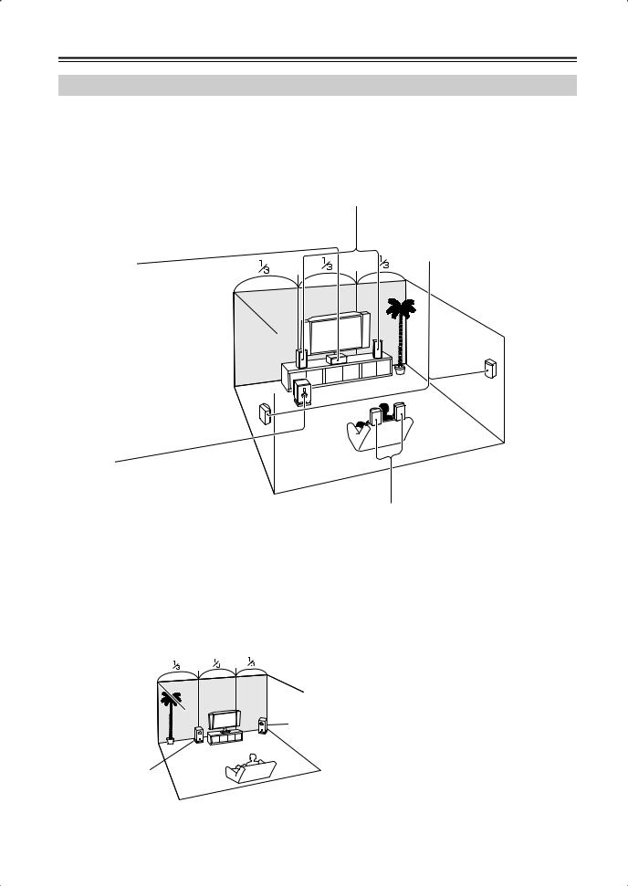
Enjoying Home Theater
Thanks to the AV receiver’s superb capabilities, you can enjoy surround sound with a real sense of movement in your own home—just like being in a movie theater or concert hall. You can enjoy DVDs featuring Dolby Digital or DTS. With analog or digital TV, you can enjoy Dolby Pro Logic IIx, DTS Neo:6, or Onkyo’s original DSP listening modes.
Front left and right speakers
These output the main sound. Their role in a home theater is to provide a solid anchor for the sound image. They should be positioned facing the listener at about ear level, and equally spaced from the TV. Angle them inward slightly so as to create a triangle, with the listener at the apex.
Center speaker
This speaker enhances the front left and right speakers, making sound movements distinct and providing a full sound image. For movies it’s used mainly for dialog.
Position it close to your TV (preferably on top) facing forward at about ear level, or at the same height as the front left and right speakers.
Surround left and right speakers
These speakers are used for precise sound positioning and to add realistic ambience.
Position them at the sides of the listener, or slightly behind, about 2–3 feet (60–100 cm) above ear level. Ideally they should be equally spaced from the listener.
Subwoofer
The subwoofer handles the bass sounds of the LFE (Low-Frequency Effects) channel. The volume and quality of the bass output from your subwoofer will depend on its position, the shape of your listening room, and your listening position. In general, a good bass sound can be obtained by installing the subwoofer in a front corner, or at one-third the way along the front wall, as shown.
Tip: To find the best position for your subwoofer, while playing a movie or some music with good bass, experiment by placing your subwoofer at various positions within the room and choose the one that provides the most satisfying results.
Corner position
1/3 of wall position
Surround back left and right speakers
These speakers are necessary to enjoy Dolby Digital EX, DTS-ES Matrix, DTS-ES Discrete, etc. They enhance the realism of surround sound and improve sound localization behind the listener. Position them behind the listener about 2–3 feet (60–100 cm) above ear level.
14
Connecting Your Speakers—Continued
Speaker Configuration
For 7.1-channel surround-sound playback, you need seven speakers and a powered subwoofer.
The following table shows which channels you should use based on the number of speakers you have.
Number of speakers: |
2 |
3 |
4 |
5 |
6 |
7 |
|
|
|
|
|
|
|
Front left |
|
|
|
|
|
|
|
|
|
|
|
|
|
Front right |
|
|
|
|
|
|
|
|
|
|
|
|
|
Center |
|
|
|
|
|
|
|
|
|
|
|
|
|
Surround left |
|
|
|
|
|
|
|
|
|
|
|
|
|
Surround right |
|
|
|
|
|
|
|
|
|
|
|
|
|
Surround back* |
|
|
|
|
|
|
|
|
|
|
|
|
|
Surround back left |
|
|
|
|
|
|
|
|
|
|
|
|
|
Surround back right |
|
|
|
|
|
|
|
|
|
|
|
|
|
*If you’re using only one surround back speaker, connect it to the SURR BACK L terminals.
No matter how many speakers you use, a powered subwoofer is recommended for a powerful and solid bass.
To get the best from your surround-sound system, you must set the speaker settings. You can do this automatically (see page 39) or manually (see page 82).
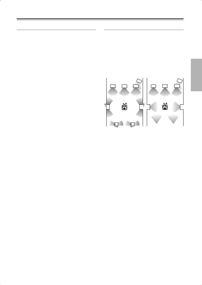
Using Dipole Speakers
You can use dipole speakers for the surround left and right and surround back left and right speakers. Dipole speakers output the same sound in two directions.
Dipole speakers typically have an arrow printed on them to indicate how they should be positioned. The surround left and right dipole speakers should be positioned so that their arrows point toward your TV or screen, while the surround back left and right dipolar speakers should be positioned so that their arrows point toward each other, as shown.
Dipole speakers |
|
|
Normal speakers |
|
||||
|
|
|
|
|
|
|
|
|
|
|
|
1 |
|
|
|
|
1 |
|
TV/screen |
|
|
TV/screen |
|
|||
2 |
3 |
4 |
2 |
3 |
4 |
5 |
6 |
5 |
6 |
|
7 |
|
|
8 |
|
|
7 |
|
8 |
|
|
1. Subwoofer |
|
|
6. Surround right speaker |
||||||||
2. Front left speaker |
7. Surround back left |
||||||||||
3. Center speaker |
|
|
|
speaker |
|
|
|||||
4. Front right speaker |
8. Surround back right |
||||||||||
5. Surround left speaker |
|
speaker |
|
|
|||||||
15
Connecting Your Speakers—Continued
Speaker Connection Precautions
Read the following before connecting your speakers:
•North American models: You can connect speakers with an impedance of between 6 and 16 ohms. If you use speakers with a lower impedance, and use the amplifier at high volume levels for a long period of time, the built-in amp protection circuit may be activated.
•Other models: You can connect speakers with an impedance of between 4 and 16 ohms. If the impedance of any of the connected speakers is 4 ohms or more, but less than 6 ohms, be sure to set the minimum speaker impedance to “4 ohms” (see page 43). If you use speakers with a lower impedance, and use the amplifier at high volume levels for a long period of time, the built-in amp protection circuit may be activated.
•Disconnect the power cord from the wall outlet before making any connections.
•Read the instructions supplied with your speakers.
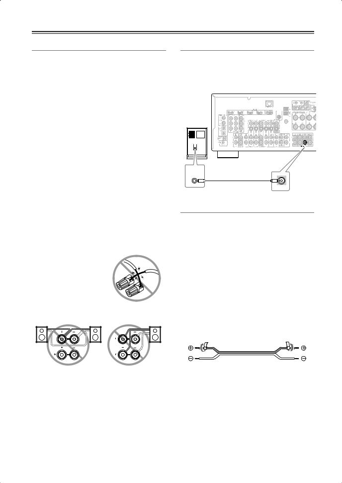
•Pay close attention to speaker wiring polarity. Connect positive (+) terminals to only positive (+) terminals, and negative (–) terminals to only negative (–) terminals. If you get them the wrong way around, the sound will be out of phase and will sound unnatural.
•Unnecessarily long or very thin speaker cables may affect the sound quality and should be avoided.
•Be careful not to short the positive and negative wires.
Doing so may damage the AV receiver.
• Don’t connect more than one cable to each speaker terminal. Doing so may damage the AV receiver.
• Don’t connect a speaker to several terminals.
Connecting a Powered Subwoofer
Using a suitable cable, connect the AV receiver’s PRE OUT: SUBWOOFER to the input on your powered subwoofer. If your subwoofer is unpowered and you’re using an external amplifier, connect the PRE OUT: SUBWOOFER to the amp’s input.
SIRIUS |
AM |
Powered
ANTENNA
subwoofer |
FM |
|
75 |
LINE INPUT
SUBWOOFER
PRE OUT
Attaching the Speaker Labels
The AV receiver’s positive (+) speaker terminals are all red. (The negative (–) speaker terminals are all black.)
Speaker |
Color |
Front left |
White |
|
|
Front right |
Red |
|
|
Center |
Green |
|
|
Surround left |
Blue |
|
|
Surround right |
Gray |
|
|
Surround back left |
Brown |
|
|
Surround back right |
Tan |
|
|
The supplied speaker labels are color-coded and you should attach them to the positive (+) side of each speaker cable in accordance with the above table. All you need to do then is to match the color of each label to the corresponding speaker terminal.
16
Connecting Your Speakers—Continued
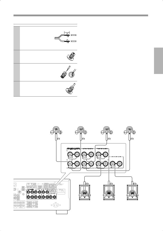
Connecting the Speaker Cables
1 |
Strip about 5/8" (15 |
5/8" (15 mm) |
|
mm) of insulation from |
|
|
the ends of the |
|
|
speaker cables, and |
|
|
twist the bare wires |
|
|
tightly, as shown. |
|
2 |
Unscrew the terminal. |
|
3 |
Fully insert the bare wire. |
|
4 Screw the terminal tight.
The following illustration shows which speaker should be connected to each pair of terminals.
If you’re using only one surround back speaker, connect it to the left (L) SURR BACK SPEAKERS terminals.
|
|
|
|
|
|
|
|
|
Surround back |
|
|
|
Surround back |
|
|
|
Surround left |
|
Surround right |
||||||||||||||||||||||||||||||||||||||||||||||||||||||||||||||||
|
|
|
|
|
|
|
|
|
|
left speaker |
|
|
|
right speaker |
|
|
|
|
|
speaker |
|
|
speaker |
||||||||||||||||||||||||||||||||||||||||||||||||||||||||||||
|
|
|
|
|
|
|
|
|
|
|
|
|
|
|
|
|
|
|
|
|
|
|
|
|
|
|
|
|
|
|
|
|
|
|
|
|
|
|
|
|
|
|
|
|
|
|
|
|
|
|
|
|
|
|
|
|
|
|
|
|
|
|
|
|
|
|
|
|
|
|
|
|
|
|
|
|
|
|
|
|
|
|
|
|
|
|
|
|
|
|
|
|
|
|
|
|
|
|
|
|
|
|
|
|
|
|
|
|
|
|
|
|
|
|
|
|
|
|
|
|
|
|
|
|
|
|
|
|
|
|
|
|
|
|
|
|
|
|
|
|
|
|
|
|
|
|
|
|
|
|
|
|
|
|
|
|
|
|
|
|
|
|
|
|
|
|
|
|
|
|
|
|
|
|
|
|
|
|
|
|
|
|
|
|
|
|
|
|
|
|
|
|
|
|
|
|
|
|
|
|
|
|
|
|
|
|
|
|
|
|
|
|
|
|
|
|
|
|
|
|
|
|
|
|
|
|
|
|
|
|
|
|
|
|
|
|
|
|
|
|
|
|
|
|
|
|
|
|
|
|
|
|
|
|
|
|
|
|
|
|
|
|
|
|
|
|
|
|
|
|
|
|
|
|
|
|
|
|
|
|
|
|
|
|
|
|
|
|
|
|
|
|
|
|
|
|
|
|
|
|
|
|
|
|
|
|
|
|
|
|
|
|
|
|
|
|
|
|
|
|
|
|
|
|
|
|
|
|
|
|
|
|
|
|
|
|
|
|
|
|
|
|
|
|
|
|
|
|
|
|
|
|
|
|
|
|
|
|
|
|
|
|
|
|
|
|
|
|
|
|
|
|
|
|
|
|
|
|
|
|
|
|
|
|
|
|
|
|
|
|
|
|
|
|
|
|
|
|
|
|
|
|
|
|
|
|
|
|
|
|
|
|
|
|
|
|
|
|
|
|
|
|
|
|
|
|
|
|
|
|
|
|
|
|
|
|
|
|
|
|
|
|
|
|
|
|
|
|
|
|
|
|
|
|
|
|
|
|
|
|
|
|
|
|
|
|
|
|
|
|
|
|
|
|
|
|
|
|
|
|
|
|
|
|
|
|
|
|
|
|
|
|
|
|
|
|
|
|
|
|
|
|
|
|
|
|
|
|
|
|
|
|
|
|
|
|
|
|
|
|
|
|
|
|
|
|
|
|
|
|
|
|
|
|
|
|
|
|
|
|
|
|
|
|
|
|
|
|
|
|
|
|
|
|
|
|
|
|
|
|
|
|
|
|
|
|
|
|
|
|
|
|
|
|
|
|
|
|
|
|
|
|
|
|
|
|
|
|
|
|
|
|
|
|
|
|
|
|
|
|
|
|
|
|
|
|
|
|
|
|
|
|
|
|
|
|
|
|
|
|
|
|
|
|
|
|
|
|
|
|
|
|
|
|
|
|
|
|
|
|
|
|
|
|
|
|
|
|
|
|
|
|
|
|
|
|
|
|
|
|
|
|
|
|
|
|
|
|
|
|
|
|
|
|
|
|
|
|
|
|
|
|
|
|
|
|
|
|
|
|
|
|
|
|
|
|
|
|
|
|
|
|
|
|
|
|
|
|
|
|
|
|
|
|
|
|
|
|
|
|
|
|
|
|
|
|
|
|
|
|
|
|
|
|
|
|
|
|
|
|
|
|
|
|
|
|
|
|
|
|
|
|
|
|
|
|
|
|
|
|
|
|
|
|
|
|
|
|
|
|
|
|
|
|
|
|
|
|
|
|
|
|
|
|
|
|
|
|
|
|
|
|
|
|
|
|
|
|
|
|
|
|
|
|
|
|
|
|
|
|
|
|
|
|
|
|
|
|
|
|
|
|
|
|
|
|
|
|
|
|
|
|
|
|
|
|
|
|
|
|
|
|
|
|
|
|
|
|
|
|
|
|
|
|
|
|
|
|
|
|
|
|
|
|
|
|
|
|
|
|
|
|
|
|
|
|
|
|
|
|
|
|
|
|
|
|
|
|
|
|
|
|
|
|
|
|
|
|
|
|
|
|
|
|
|
|
|
|
|
|
|
|
|
|
|
|
|
|
|
|
|
|
|
|
|
|
|
|
|
|
|
|
|
|
|
|
|
|
|
|
|
|
|
|
|
|
|
|
|
|
|
|
|
|
|
|
|
|
|
|
|
|
|
|
|
|
|
|
|
|
|
|
|
|
|
|
|
|
|
|
|
|
|
|
|
|
|
|
|
|
|
|
|
|
|
|
|
|
|
|
|
|
|
|
|
|
|
|
|
|
|
|
|
|
|
|
|
|
|
|
|
|
|
|
|
|
|
|
|
|
|
|
|
|
|
|
|
|
|
|
|
|
|
|
|
|
|
|
|
|
|
|
|
|
|
|
|
|
|
|
|
|
|
|
|
|
|
|
|
|
|
|
|
|
|
|
|
|
|
|
|
|
|
|
|
|
|
|
|
|
|
|
|
|
|
|
|
|
|
|
|
|
|
|
|
|
|
|
|
|
|
|
|
|
|
|
|
|
|
|
|
|
|
|
|
|
|
|
|
|
|
|
|
|
|
|
|
|
|
|
|
|
|
|
|
|
|
|
|
|
|
|
|
|
|
|
|
|
|
|
|
|
|
|
|
|
|
|
|
|
|
|
|
|
|
|
|
|
|
|
|
|
|
|
|
|
|
|
|
|
|
|
|
|
|
|
|
|
|
|
|
|
|
|
|
|
|
|
|
|
|
|
|
|
|
|
|
|
|
|
|
|
|
|
|
|
|
|
|
|
|
|
|
|
|
|
|
|
|
|
|
|
|
|
|
|
|
|
|
|
|
|
|
|
|
|
|
|
|
|
|
|
|
|
|
|
|
|
|
|
|
|
|
|
|
|
|
|
|
|
|
|
|
|
|
|
|
|
|
|
|
|
|
|
|
|
|
|
|
|
|
|
|
|
|
|
|
|
|
|
|
|
|
|
|
|
|
|
|
|
|
|
|
|
|
|
|
|
|
|
|
|
|
|
|
|
|
|
|
|
|
|
|
|
|
|
|
|
|
|
|
|
|
|
|
|
|
|
|
|
|
|
|
|
|
|
|
|
|
|
|
|
|
|
|
|
|
|
|
|
|
|
|
|
|
|
|
|
|
|
|
|
|
|
|
|
|
|
|
|
|
|
|
|
|
|
|
|
|
|
|
|
|
|
|
|
|
|
|
|
|
|
|
|
|
|
|
|
|
|
|
|
|
|
|
|
|
|
|
|
|
|
|
|
|
|
|
|
|
|
|
|
|
|
|
|
|
|
|
|
|
|
|
|
|
|
|
|
|
|
|
|
|
|
|
|
|
|
|
|
|
|
|
|
|
|
|
|
|
|
|
|
|
|
|
|
|
|
|
|
|
|
|
|
|
|
|
|
|
|
|
SIRIUS |
AM |
ANTENNA
FM |
75 |
|
|
|
|
|
|
|
Front right |
Front left |
Center |
|
|
|
|
|
|
|
|||
|
|
|
|
|
|
|
speaker |
speaker |
speaker |
|
|
|
|
|
|
|
|
|
|
|
|
|
|
|
|
|
|
|
|
|
|
|
|
|
|
|
|
|
|
17
Connecting Your Speakers—Continued
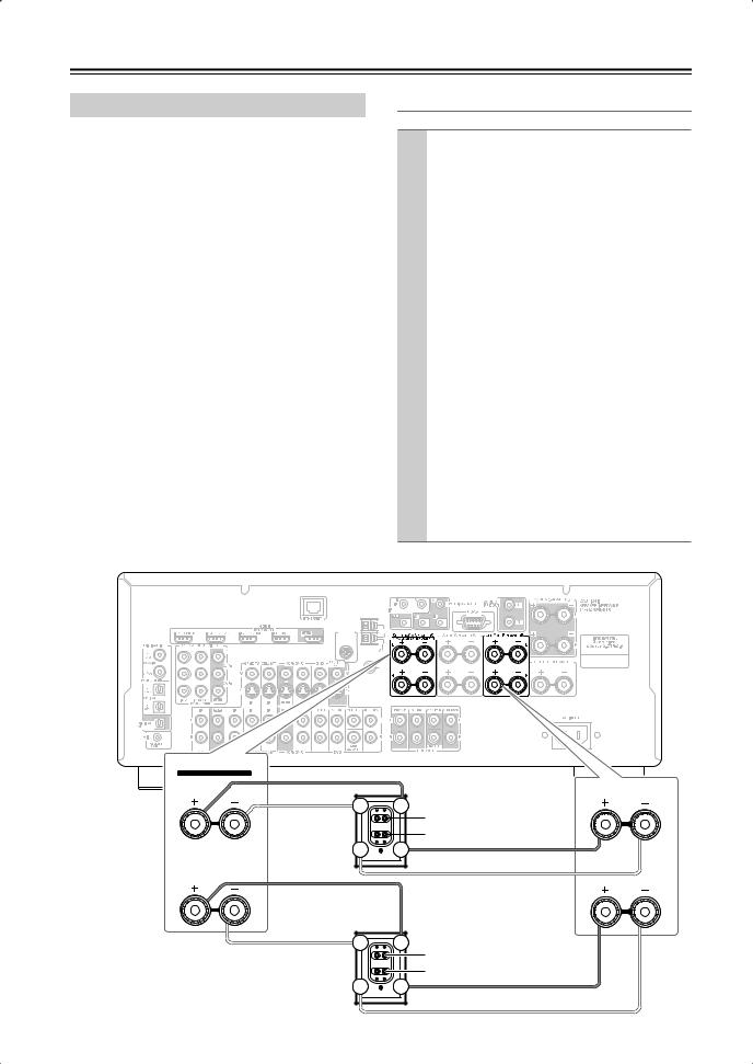
Bi-amping Front Speakers
The FRONT L/R and SURR BACK L/R terminal posts can be used with front speakers and surround back speakers respectively, or bi-amped to provide separate tweeter and woofer feeds for front speakers, providing improved bass and treble performance.
•When bi-amping is used, the AV receiver is able to drive up to 5.1 speakers in the main room.
•For bi-amping, the FRONT L/R terminal posts connect to the front speakers’ tweeter terminals. And the SURR BACK L/R terminal posts connect to the front speakers’ woofer terminals.
•Once you’ve completed the bi-amping connections shown below and turned on the AV receiver, you must set the Speaker Type setting to Bi-Amp to enable biamping (see page 43).
Important:
•When making the bi-amping connections, be sure to remove the jumper bars that link the speakers’ tweeter (high) and woofer (low) terminals.
•Bi-amping can only be used with speakers that support bi-amping. Refer to your speaker manual.
Bi-amping Speaker Hookup
1 |
Connect the AV receiver’s FRONT R positive (+) |
|
terminal to the right speaker’s positive (+) tweeter |
|
(high) terminal. And connect the AV receiver’s |
|
FRONT R negative (–) terminal to the right |
|
speaker’s negative (–) tweeter (high) terminal. |
|
|
2 |
Connect the AV receiver’s SURR BACK R posi- |
|
tive (+) terminal to the right speaker’s positive (+) |
|
woofer (low) terminal. And connect the AV |
|
receiver’s SURR BACK R negative (–) terminal to |
|
the right speaker’s negative (–) woofer (low) ter- |
|
minal. |
|
|
3 |
Connect the AV receiver’s FRONT L positive (+) |
|
terminal to the left speaker’s positive (+) tweeter |
|
(high) terminal. And connect the AV receiver’s |
|
FRONT L negative (–) terminal to the left |
|
speaker’s negative (–) tweeter (high) terminal. |
|
|
4 |
Connect the AV receiver’s SURR BACK L posi- |
tive (+) terminal to the left speaker’s positive (+) woofer (low) terminal. And connect the AV receiver’s SURR BACK L negative (–) terminal to the left speaker’s negative (–) woofer (low) terminal.
SIRIUS |
AM |
ANTENNA
FM 75
SURR BACK SPEAKERS
Bi-AMP for FRONT SPEAKERS
|
FRONT SPEAKERS |
L |
L |
|
Left speaker |
Woofer (low) |
|
Tweeter (high) |
|
|
|
|
R |
|
R |
Right speaker |
Woofer (low) |
|
Tweeter (high) |
||
|
18
Connecting Antennas
This section explains how to connect the supplied indoor FM antenna and AM loop antenna, and how to connect commercially available outdoor FM and AM antennas.
The AV receiver won’t pick up any radio signals without any antenna connected, so you must connect the antenna to use the tuner.
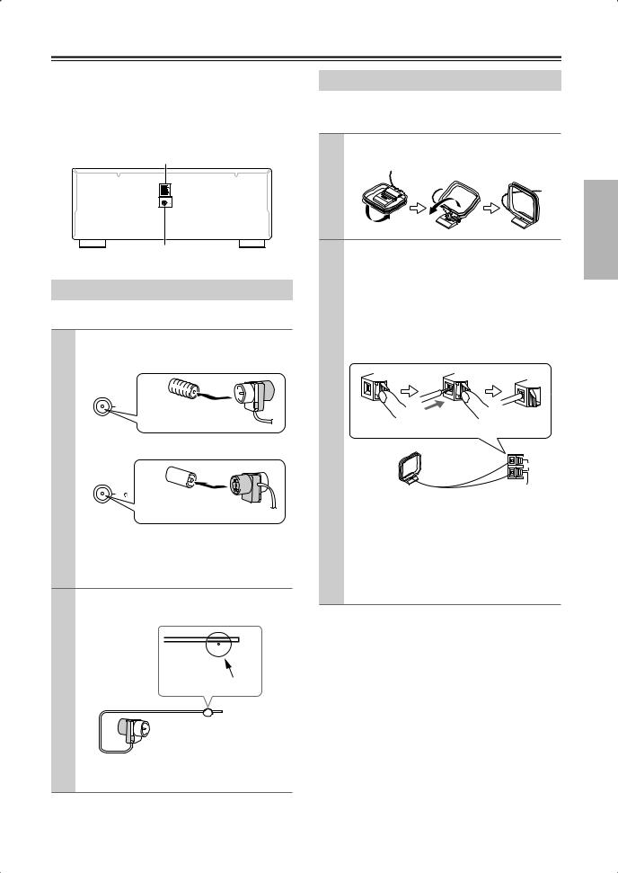
AM antenna push terminals
AM |
ANTENNA |
FM |
75 |
FM antenna jack
Connecting the Indoor FM Antenna
The supplied indoor FM antenna is for indoor use only.
1 Attach the FM antenna, as shown.
■ American Model
FM
75 Insert the plug fully into the jack.
■ Other Models
FM
75
Insert the plug fully into the jack.
Once your AV receiver is ready for use, you’ll need to tune into an FM radio station and adjust the position of the FM antenna to achieve the best possible reception.
2 Use thumbtacks or something similar to fix the FM antenna into position.
Thumbtacks, etc.
Caution: Be careful that you don’t injure yourself when using thumbtacks.
If you cannot achieve good reception with the supplied indoor FM antenna, try a commercially available outdoor FM antenna instead (see page 20).
Connecting the AM Loop Antenna
The supplied indoor AM loop antenna is for indoor use only.
1 Assemble the AM loop antenna, inserting the tabs into the base, as shown.
2 Connect both wires of the AM loop antenna to the AM push terminals, as shown.
(The antenna’s wires are not polarity sensitive, so they can be connected either way around).
Make sure that the wires are attached securely and that the push terminals are gripping the bare wires, not the insulation.
Push |
Insert wire |
Release |
|
|
AM |
|
|
ANTENNA |
Once your AV receiver is ready for use, you’ll need to tune into an AM radio station and adjust the position of the AM antenna to achieve the best possible reception.
Keep the antenna as far away as possible from your AV receiver, TV, speaker cables, and power cords.
If you cannot achieve good reception with the supplied indoor AM loop antenna, try using it with a commercially available outdoor AM antenna (see page 20).
19
Connecting Antennas—Continued
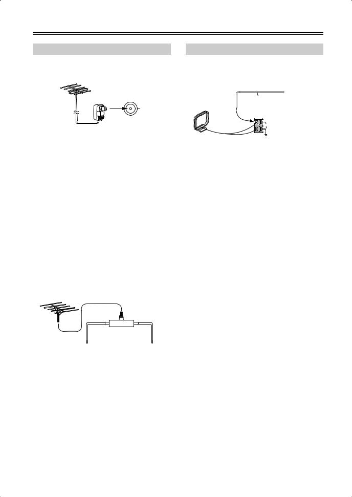
Connecting an Outdoor FM Antenna
If you cannot achieve good reception with the supplied indoor FM antenna, try a commercially available outdoor FM antenna instead.
FM 75
Notes:
•Outdoor FM antennas work best outside, but usable results can sometimes be obtained when installed in an attic or loft.
•For best results, install the outdoor FM antenna well away from tall buildings, preferably with a clear line of sight to your local FM transmitter.
•Outdoor antenna should be located away from possible noise sources, such as neon signs, busy roads, etc.
•For safety reasons, outdoor antenna should be situated well away from power lines and other high-voltage equipment.
•Outdoor antenna must be grounded in accordance with local regulations to prevent electrical shock hazards.
■ Using a TV/FM Antenna Splitter
It’s best not to use the same antenna for both FM and TV reception, as this can cause interference problems. If circumstances demand it, use a TV/FM antenna splitter, as shown.
TV/FM antenna splitter
To AV receiver |
To TV (or VCR) |
Connecting an Outdoor AM Antenna
If good reception cannot be achieved using the supplied AM loop antenna, an outdoor AM antenna can be used in addition to the loop antenna, as shown.
Outdoor antenna
Insulated antenna cable
AM loop antenna
AM
ANTENNA
Outdoor AM antennas work best when installed horizontally outside, but good results can sometimes be obtained indoors by mounting horizontally above a window. Note that the AM loop antenna should be left connected.
Outdoor antenna must be grounded in accordance with local regulations to prevent electrical shock hazards.
20
Connecting Your Components
About AV Connections
•Before making any AV connections, read the manuals supplied with your other AV components.
•Don’t connect the power cord until you’ve completed and double-checked all AV connections.
Optical Digital Jacks
The AV receiver’s optical digital jacks have shutter-type covers that open when an optical plug is inserted and close when it’s removed. Push plugs in all the way.
Caution: To prevent shutter damage, hold the optical plug straight when inserting and removing.
AV Cables and Jacks
AV Connection Color Coding
RCA-type AV connections are usually color coded: red, white, and yellow. Use red plugs to connect rightchannel audio inputs and outputs (typically labeled “R”). Use white plugs to connect left-channel audio inputs and outputs (typically labeled “L”). And use yellow plugs to connect composite video inputs and outputs.
Left (white) |
Analog audio |
Left (white) |
|
||
Right (red) |
|
Right (red) |
(Yellow) |
Composite video |
(Yellow) |
|
• |
Push plugs in all the way to make |
|
|
|
|
|
|
Right! |
||||||||||
|
good connections (loose connections |
|
|
|
|
|
|
|
|
|
|
|
|
|
|
|
|
|
|
can cause noise or malfunctions). |
|
|
|
|
|
|
|
|
|
|
|
|
|
|
|
|
|
• To prevent interference, keep audio |
|
|
|
|
|
|
|
|
|
|
|
|
|
|
|
|
|
|
|
and video cables away from power |
|
|
|
|
|
|
Wrong! |
||||||||||
|
|
|
|
|
|
|
||||||||||||
|
cords and speaker cables. |
|
|
|
|
|
|
|||||||||||
|
|
|
|
|
|
|
|
|
|
|
|
|
|
|
|
|
|
|
Audio/Video
Cable |
Jack |
Description |
HDMI connections can carry uncompressed stan-
HDMI
HDMI 


 dardor high-definition digital video and audio and offer the best picture and sound quality.
Video
|
Y |
Y |
Y |
Component video separates the luminance (Y) and |
Component |
PB |
PB |
CB/PB |
color difference signals (PR, PB), providing the best |
video cable |
|
|
picture quality. (Some TV manufacturers label their |
|
PR |
PR |
|
||
|
|
component video jacks slightly differently.) |
||
|
|
|
CR/PR |
|
|
|
|
|
S-Video separates the luminance and color signals |
S-Video cable |
|
|
S |
and provides better picture quality than composite |
|
|
|
|
video. |
Composite |
|
|
V |
Composite video is commonly used on TVs, VCRs, |
video cable |
|
|
|
and other video equipment. |
Audio
Optical digital audio cable
Coaxial digital audio cable
Analog audio cable (RCA)
Multichannel analog audio cable (RCA)
This offers the best sound quality and allows you to
OPTICAL
enjoy Dolby Digital and DTS. The audio quality is the same as for coaxial.
This offers the best sound quality and allows you to
COAXIAL
enjoy Dolby Digital and DTS. The audio quality is the same as for optical.
|
L |
This cable carries analog audio. It’s the most |
|
||
|
R |
common connection format for analog audio and |
|
can be found on virtually all AV components. |
|
|
|
This cable carries multichannel analog audio and is typically used to connect DVD players with a 7.1- channel analog audio output. Several standard analog audio cables can be used instead of a multichannel cable.
Note: The AV receiver does not support SCART connections.
21
Connecting Your Components—Continued
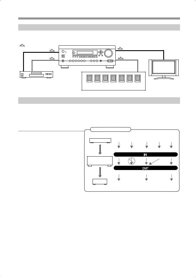
Connecting Audio and Video Signals to the AV Receiver
By connecting both the audio and video outputs of your DVD player and other AV components to the AV receiver, you can switch the audio and video signals simultaneously simply by changing the input source on the AV receiver.
: Signal Flow |
|
Video |
Video |
|
|
Audio |
Audio |
|
TV, projector, |
|
etc. |
DVD player, etc. |
|
|
Speakers (see page 17 for hookup details) |
Which Connections Should I Use?
The AV receiver supports several connection formats for compatibility with a wide range of AV equipment. The format you choose will depend on the formats supported by your other components. Use the following sections as a guide.
For video components, you must make an audio connection and a video connection.
Audio Connection Formats
Audio equipment can be connected to the AV receiver by using any of the following audio connection formats: analog, optical, coaxial, analog multichannel, or HDMI.
When you connect audio equipment to an HDMI, OPTICAL, or COAXIAL input, you must assign that input to an input selector (see pages 45).
When choosing a connection format, bear in mind that the AV receiver does not convert digital input signals for analog line outputs and vice versa. For example, audio signals connected to an optical or coaxial digital input are not output by the analog TAPE OUT.
Audio Signal Flow Chart
DVD player, etc.
HDMI Multichannel Optical Coaxial Analog
AV receiver
HDMI |
Optical |
Analog |
MD recorder, etc.
If signals are present at more than one input, the inputs will be selected automatically in the following order of priority: HDMI, digital, analog (including multichannel). You can specify which audio inputs the AV receiver checks for the presence of a signal in the “Automatic Audio Input Selection Setup” on page 47.
22
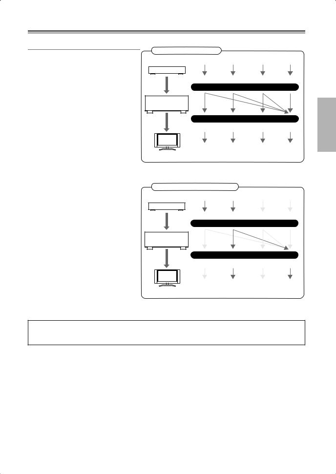
Connecting Your Components—Continued
Video Connection Formats
Video equipment can be connected to the AV receiver by using any one of the following video connection formats: composite video, S-Video, component video, or HDMI, the latter offering the best picture quality.
Video input signals flow through the AV receiver as shown, with composite video, S- Video, and component video sources all being upconverted for the HDMI output.
The composite video, S-Video, and component video outputs pass through their respective input signals as they are.
When you connect audio equipment to an HDMI or COMPONENT input, you must assign that input to an input selector (see pages 44 and 45).
If signals are present at more than one input, the inputs will be selected automatically in the following order of priority: HDMI, component video, S-Video, composite video. However, for component video only, regardless of whether a component video signal is actually present, if a component video input is assigned to the input selector, that component video input will be selected. And if no component video input is assigned to the input selector, this will be interpreted as no component video signal being present.
In the Signal Selection Example shown on the right, video signals are present at both the S-Video and composite video inputs, however, the S-Video signal is automatically selected as the source and video is output by the S-Video and HDMI outputs.
Video Signal Flow Chart
DVD player, etc.
Composite |
S-Video |
Component |
HDMI |
IN
AV receiver
MONITOR OUT
Composite |
S-Video |
Component |
HDMI |
TV, projector, etc.
Signal Selection Example
DVD player, etc.
Composite |
S-Video |
Component |
HDMI |
IN
AV receiver
MONITOR OUT
Composite |
S-Video |
Component |
HDMI |
TV, projector, etc.
The onscreen setup menus appear only on a TV that is connected to the HDMI OUT. If your TV is connected to the composite video or S-Video MONITOR OUT, or the COMPONENT VIDEO OUT, use the DTR-5.9’s display when changing settings.
23
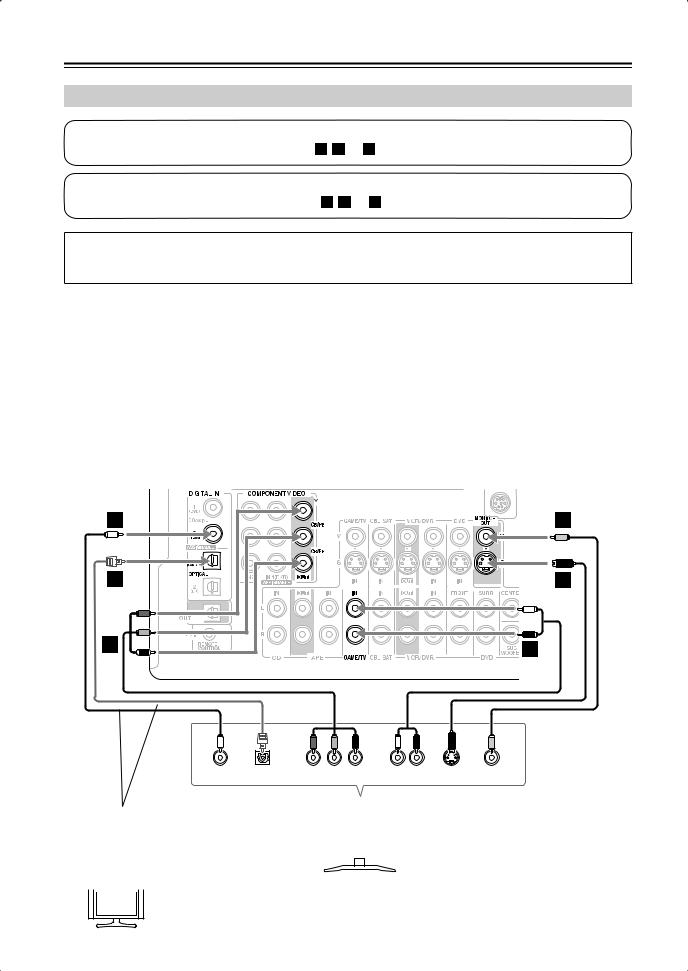
Connecting Your Components—Continued
Connecting a TV or Projector
Step 1: Video Connection
Choose a video connection that matches your TV ( A , B , or C ), and then make the connection.
Step 2: Audio Connection
Choose an audio connection that matches your TV ( a , b , or c ), and then make the connection.
The onscreen setup menus appear only on a TV that is connected to the HDMI OUT. If your TV is connected to the composite video or S-Video MONITOR OUT, or the COMPONENT VIDEO OUT, use the DTR-5.9’s display when changing settings.
•With connection  , you can listen to and record audio from your TV or listen in Zone 2.
•To enjoy Dolby Digital and DTS, use connection  or
or  . (To record or listen in Zone 2 as well, use
  and
and  , or
, or  and
and  .)
.)
Connection |
|
|
AV receiver |
|
Signal flow |
TV |
Picture quality |
|||||
|
A |
|
COMPONENT VIDEO OUT |
|
|
Component video input |
Best |
|||||
|
|
|
|
MONITOR OUT S |
|
|
S-Video input |
Better |
||||
|
B |
|||||||||||
|
|
|
|
|
|
|
|
|
|
|
|
|
|
C |
|
|
MONITOR OUT V |
|
|
Composite video input |
Standard |
||||
|
|
|
|
GAME/TV IN L/R |
|
|
Analog audio L/R output |
|
||||
|
a |
|
||||||||||
|
|
|
|
|
|
|
|
|
|
|
|
|
|
b |
|
DIGITAL IN COAXIAL 2 |
|
|
Digital coaxial output |
|
|||||
|
|
|
DIGITAL IN OPTICAL 1 |
|
|
Digital optical output |
|
|||||
|
c |
|
||||||||||
|
|
|
|
|
|
|
|
|
|
|
|
|
|
|
|
|
|
|
|
|
|
|
|
|
|
|
|
|
|
|
|
|
|
|
|
|
|
|
|
|
|
|
|
|
|
|
|
|
|
|
|
|
|
|
|
|
|
|
|
|
|
|
|
|
b |
ANTENNA |
FMC |
|
|
75 |
c |
B |
A |
a |
|
|
|
|
|
L |
|
R |
|
COAXIAL |
OPTICAL |
Y |
PB |
PR |
AUDIO |
S VIDEO |
VIDEO |
OUT |
OUT |
COMPONENT VIDEO IN |
OUT |
IN |
IN |
||
Connect one or the other |
|
|
|
|
|
||
|
|
TV, projector, |
|
|
|||
Connection |
|
must be assigned |
|
|
|
|
|
c |
|
|
|
|
|||
|
|
etc. |
|
|
|||
(see page 45) |
|
|
|
|
|
||
|
|
|
|
|
|
||
|
|
|
|
|
|
|
|
|
|
|
|
|
|
|
|
 If your TV has no audio outputs, connect an audio output from your VCR or cable or satellite Hint! receiver to the AV receiver and use its tuner to listen to TV programs through the AV receiver (see
pages 27 and 29).
24
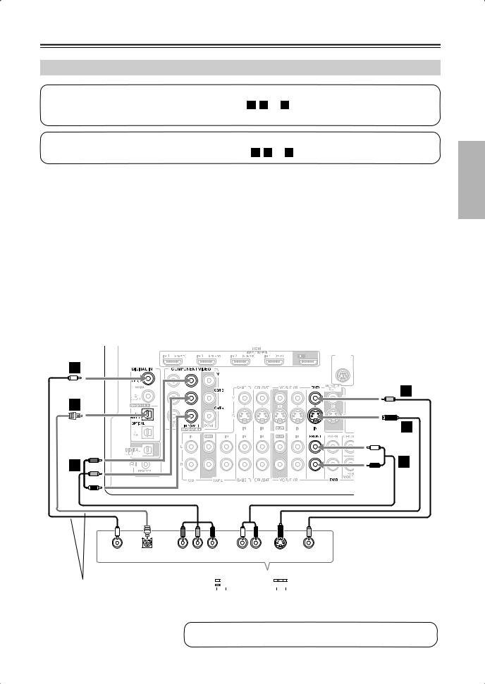
Connecting Your Components—Continued
Connecting a DVD player
Step 1: Video Connection
Choose a video connection that matches your DVD player ( A , B , or C ), and then make the connection.
You must connect the AV receiver to your TV with the same type of connection.
Step 2: Audio Connection
Choose an audio connection that matches your DVD player ( a , b , or c ), and then make the connection.
•With connection  , you can listen to and record audio from a DVD or listen in Zone 2.
•To enjoy Dolby Digital and DTS, use connection  or
or  . (To record or listen in Zone 2 as well, use
  and
and  , or
, or  and
and  .)
.)
•If your DVD player has main left and right outputs and multichannel left and right outputs, be sure to use the main left and right outputs for connection  .
.
Connection |
AV receiver |
Signal flow |
|
DVD player |
Picture quality |
|||||||||
|
A |
|
COMPONENT VIDEO IN 1 |
|
|
Component video output |
|
Best |
||||||
|
|
|
DVD IN S |
|
|
|
S-Video output |
|
Better |
|||||
|
B |
|||||||||||||
|
|
|
|
|
|
|
|
|
|
|
|
|
|
|
|
C |
|
DVD IN V |
|
|
Composite video output |
|
Standard |
||||||
|
|
|
DVD IN FRONT L/R |
|
|
Analog audio L/R output |
|
|
||||||
|
a |
|
|
|||||||||||
|
|
|
|
|
|
|
|
|
|
|
|
|
|
|
|
b |
|
DIGITAL IN COAXIAL 1 |
|
|
Digital coaxial output |
|
|
||||||
|
|
|
DIGITAL IN OPTICAL 1 |
|
|
Digital optical output |
|
|
||||||
|
c |
|
|
|||||||||||
|
|
|
|
|
|
|
|
|
|
|
|
|
|
|
|
|
|
|
|
|
|
|
|
|
|
|
|
|
|
|
|
|
|
|
|
|
|
|
|
|
|
|
|
|
|
|
|
|
|
|
|
|
|
|
|
|
|
|
|
|
|
|
|
|
|
|
|
|
|
|
|
|
AM |
|
|
|
|
|
|
|
|
|
|
|
|
SIRIUS |
|
|
|
|
|
|
|
|
|
|
|
|
|
|
|
|
||
|
|
|
|
|
|
|
|
|
|
|
|
|
|
|
|
|
|
|
|
|
|
|
|
|
|
|
|||
|
|
|
|
|
|
|
|
|
|
|
|
|
|
|
b
ANTENNA
FM |
C |
75 |
c
B
A |
a |
|
|
|
|
|
L |
|
R |
|
COAXIAL |
OPTICAL |
Y |
PB |
PR |
AUDIO |
S VIDEO |
VIDEO |
OUT |
OUT |
COMPONENT VIDEO OUT |
OUT |
OUT |
OUT |
||
Connect one or the other |
|
|
|
|
|
|
|
|
|
|
|
||
|
|
|
|
|
|
|
|
|
|
|
|||
|
|
|
|
|
|
|
|
|
|
|
|||
|
|
|
|
|
|
|
|
|
|
|
|||
Connection |
|
must be |
|
|
|
|
|
||||||
c |
|
|
DVD player |
||||||||||
assigned (see page 45) |
|
|
|
|
|
|
|
|
|
|
|
||
To connect a DVD player or DVD-Audio/SACD-capable player with a multichannel analog audio output, see page 26.
25
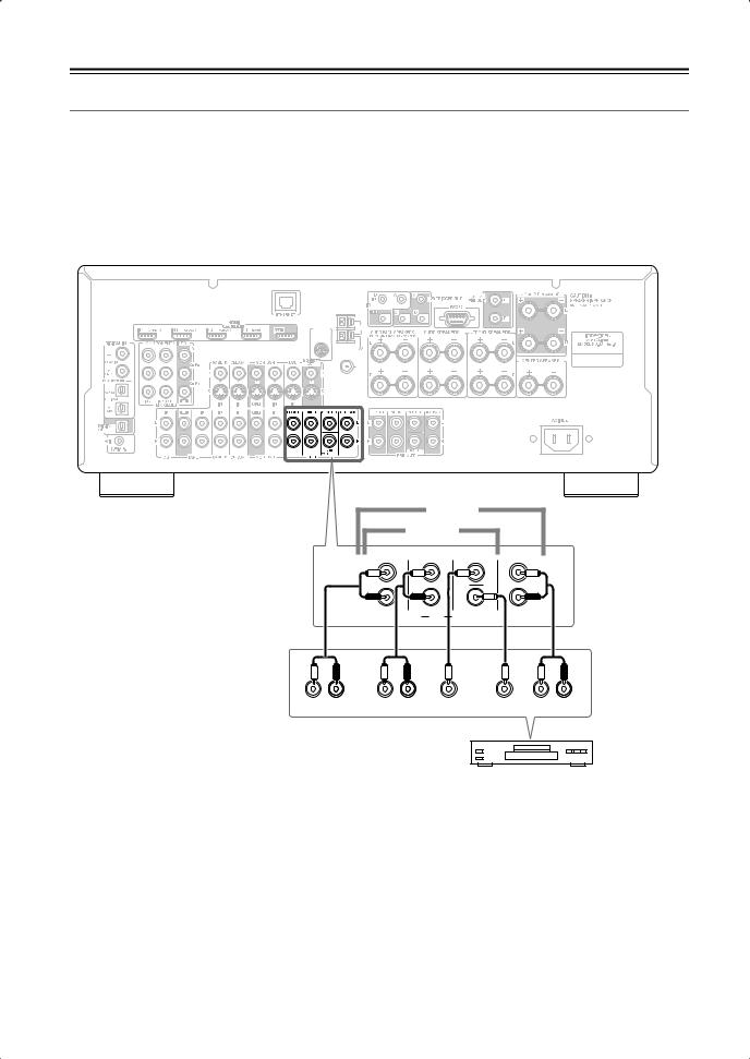
Connecting Your Components—Continued
Hooking Up the Multichannel Input
If your DVD player supports multichannel audio formats such as DVD-Audio and SACD, and it has a multichannel analog audio output, you can connect it to the AV receiver’s multichannel input.
Use a multichannel analog audio cable, or several normal audio cables, to connect the AV receiver’s DVD IN FRONT L/R, CENTER, SURR L/R, SURR BACK L/R, and SUBWOOFER jacks to the 7.1-channel analog audio output on your DVD player. If your DVD player has a 5.1-channel analog audio output, don’t connect anything to the AV receiver’s SURR BACK L/R jacks.
To select the multichannel input, see “Basic AV Receiver Operation” on page 48. To adjust the subwoofer sensitivity for the multichannel input, see “Hardware Setup” on page 89.
SIRIUS |
AM |
ANTENNA
FM 75
7.1 ch
5.1 ch
FRONT |
SURR |
CENTER |
SURR BACK |
L |
|
|
L |
R |
|
SUB |
R |
|
|
|
|
|
DVD |
WOOFER |
|
L |
R |
L |
R |
|
L |
R |
FRONT |
|
SURROUND |
CENTER |
SUB |
|
SURR |
|
|
|
|
WOOFER |
|
BACK |
DVD player
26
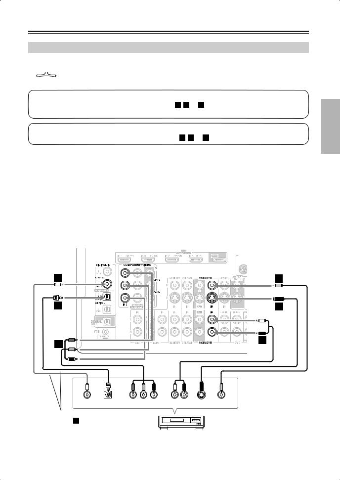
Connecting Your Components—Continued
Connecting a VCR or DVR for Playback
|
|
|
With this hookup, you can use the tuner in your VCR or DVR to listen to your favorite TV programs |
|
Hint! |
|
|
|
|
via the AV receiver, which is useful if your TV has no audio outputs. |
|
|
|
|
|
|
|
|
Step 1: Video Connection
Choose a video connection that matches your VCR or DVR ( A , B , or C ), and then make the connection. You must
connect the AV receiver to your TV with the same type of connection.
Step 2: Audio Connection
Choose an audio connection that matches your VCR or DVR ( a , b , or c ), and then make the connection.
•With connection  , you can listen to the VCR or DVR in Zone 2.
•To enjoy Dolby Digital and DTS, use connection  or
or  . (To listen in Zone 2 as well, use
  and
and  , or
, or  and
and  .)
.)
Connection |
AV receiver |
Signal flow |
VCR or DVR |
Picture quality |
|||
|
A |
|
COMPONENT VIDEO IN 2 |
|
Component video output |
Best |
|
|
|
|
VCR/DVR IN S |
|
S-Video output |
Better |
|
|
B |
||||||
|
|
|
|
|
|
|
|
|
C |
|
VCR/DVR IN V |
|
Composite video output |
Standard |
|
|
|
|
VCR/DVR IN L/R |
|
Analog audio L/R output |
|
|
|
a |
|
|||||
|
|
|
|
|
|
|
|
|
b |
|
DIGITAL IN COAXIAL 2 |
|
Digital coaxial output |
|
|
|
|
|
DIGITAL IN OPTICAL 1 |
|
Digital optical output |
|
|
|
c |
|
|||||
|
|
|
|
|
|
|
|
|
|
|
|
|
|
|
|
|
|
|
|
|
|
|
|
|
SIRIUS |
AM |
|
|
|
|
|
b |
|
ANTENNA |
C |
|
FM |
||
|
|
75 |
|
c |
|
|
B |
A |
|
a |
|
|
|
|
|
|
|
|
L |
|
R |
|
COAXIAL |
OPTICAL |
Y |
PB |
PR |
AUDIO |
S VIDEO |
VIDEO |
OUT |
OUT |
COMPONENT VIDEO OUT |
OUT |
OUT |
OUT |
||
Connect one or the other
Connection b must be
assigned (see page 45)
VCR or DVR
27
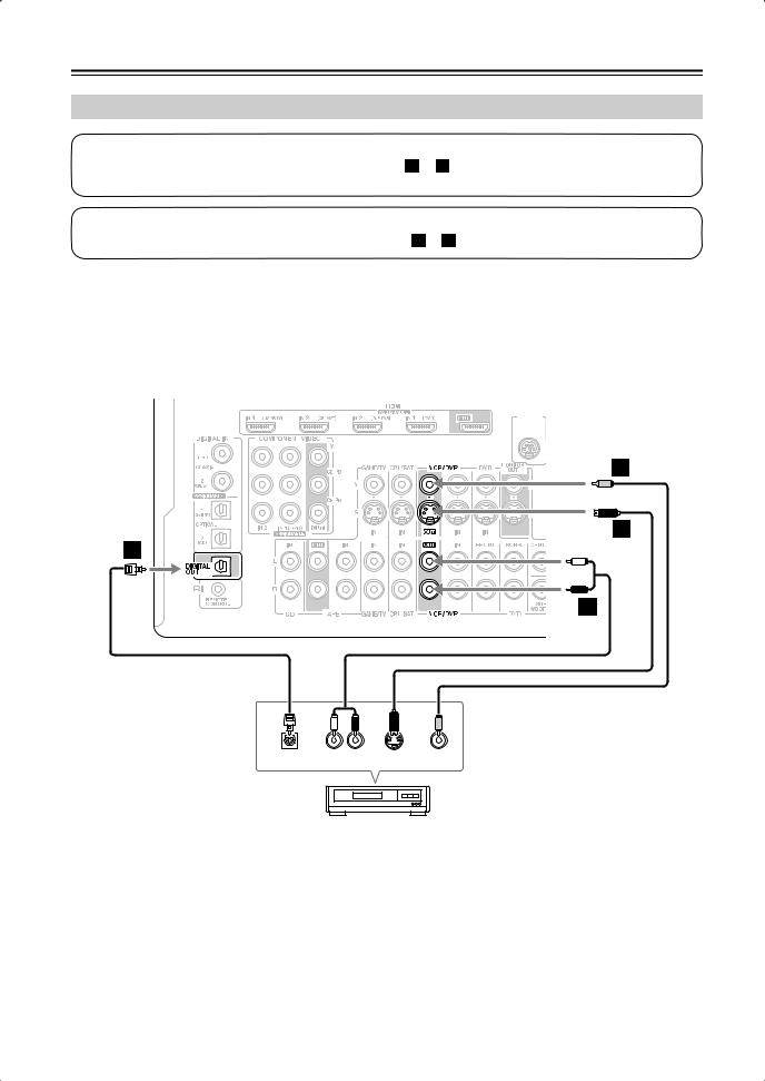
Connecting Your Components—Continued
Connecting a VCR or DVR for Recording
Step 1: Video Connection
Choose a video connection that matches your VCR or DVR ( A or B ), and then make the connection. The video source to be recorded must be connected to the AV receiver via the same type of connection.
Step 2: Audio Connection
Choose an audio connection that matches your VCR or DVR ( a or b ), and then make the connection.
Connection |
AV receiver |
Signal flow |
VCR or DVD recorder |
Picture quality |
|||||
|
A |
|
VCR/DVR OUT S |
|
S-Video input |
Better |
|||
|
|
|
VCR/DVR OUT V |
|
Composite video input |
Standard |
|||
|
B |
||||||||
|
|
|
|
|
|
|
|
|
|
|
a |
|
VCR/DVR OUT L/R |
|
Audio L/R input |
|
|||
|
|
|
DIGITAL OPTICAL OUT |
|
Digital optical input |
|
|||
|
b |
|
|||||||
|
|
|
|
|
|
|
|
|
|
|
|
|
|
|
|
|
|
|
|
|
|
|
|
|
|
|
|
|
|
|
|
|
|
|
|
|
|
|
|
SIRIUS |
AM |
|
ANTENNA
FM 75
B
A
b
a
L |
|
R |
|
OPTICAL |
AUDIO |
S VIDEO |
VIDEO |
IN |
IN |
IN |
IN |
VCR or DVR
Notes:
•The AV receiver must be turned on for recording. Recording is not possible while it’s on Standby.
•If you want to record directly from your TV or another video source without going through the AV receiver, connect the audio and video outputs from your TV or other video component directly to the recording VCR/DVR’s audio and video inputs. See the manuals supplied with your TV or VCR/DVR for details.
•Video signals connected to composite video inputs can only be recorded via the VCR/DVR OUT V jack. So if your source TV or VCR is connected to a composite video input, the recording VCR/DVR must be connected to the VCR/DVR OUT V jack. Likewise, video signals connected to S-Video inputs can only be recorded via the VCR/DVR OUT S jack. So if your source TV or VCR is connected to an S-Video input, the recording VCR/DVR must be connected to the VCR/DVR OUT S jack.
28
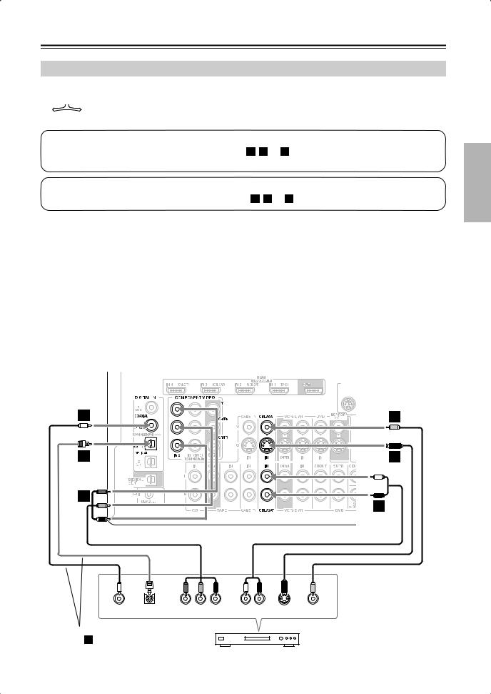
Connecting Your Components—Continued
Connecting a Satellite, Cable, Terrestrial Set-top box, or Other Video Source
|
|
|
With this hookup, you can use your satellite or cable receiver to listen to your favorite TV programs |
|
Hint! |
|
|
|
|
via the AV receiver, which is useful if your TV has no audio outputs. |
|
|
|
|
|
|
|
|
Step 1: Video Connection
Choose a video connection that matches the video source ( A , B , or C ), and then make the connection.
You must connect the AV receiver to your TV with the same type of connection.
Step 2: Audio Connection
Choose an audio connection that matches the video source ( a , b , or c ), and then make the connection.
•With connection  , you can listen to and record audio from the video source or listen in Zone 2.
•To enjoy Dolby Digital and DTS, use connection  or
or  . (To record or listen in Zone 2 as well, use
  and
and  , or
, or  and
and  .)
.)
Connection |
|
|
AV receiver |
|
Signal flow |
Video source |
Picture quality |
||||||||||||
|
A |
|
COMPONENT VIDEO IN 2 |
|
|
Component video output |
|
|
Best |
||||||||||
|
|
|
|
CBL/SAT IN S |
|
|
S-Video output |
|
|
Better |
|||||||||
|
B |
||||||||||||||||||
|
|
|
|
|
|
|
|
|
|
|
|
|
|
|
|
|
|
|
|
|
C |
|
|
CBL/SAT IN V |
|
|
Composite video output |
|
Standard |
||||||||||
|
|
|
CBL/SAT IN L/R |
|
|
Analog audio L/R output |
|
|
|
||||||||||
|
a |
|
|
|
|||||||||||||||
|
|
|
|
|
|
|
|
|
|
|
|
|
|
|
|
|
|
|
|
|
b |
|
DIGITAL IN COAXIAL 2 |
|
|
Digital coaxial output |
|
|
|
||||||||||
|
|
|
DIGITAL IN OPTICAL 1 |
|
|
Digital optical output |
|
|
|
||||||||||
|
c |
|
|
|
|||||||||||||||
|
|
|
|
|
|
|
|
|
|
|
|
|
|
|
|
|
|
|
|
|
|
|
|
|
|
|
|
|
|
|
|
|
|
|
|
|
|
|
|
|
|
|
|
|
|
|
|
|
|
|
|
|
|
|
|
|
|
|
|
|
|
|
|
|
|
|
|
|
|
|
|
|
|
|
|
|
|
|
|
|
|
|
|
|
|
|
|
|
|
|
|
|
|
|
|
|
|
AM |
|
|
|
|
|
|
|
|
|
|
|
|
|
|
|
|
SIRIUS |
|
|
|
|
|
|
|
|
|
|
|
|
|
|
|
|
|
|
|
|
|
|
||
|
|
|
|
|
|
|
|
|
|
|
|
|
|
|
|
|
|
|
|
|
|
|
|
|
|
|
|
|
|
|
|
|
|
|
|
|
|||
|
|
|
|
|
|
|
|
|
|
|
|
|
|
|
|
|
|
|
|
|
|
|
|
|
|
|
|
|
|
|
|
|
|
|
|
|
|
|
|
|
|
|
|
|
|
|
|
|
|
|
|
|
|
|
|
|
|
|
|
|
|
|
|
|
|
|
|
|
|
|
|
|
|
|
|
|
|
|
|
|
|
|
|
|
|
|
|
|
|
|
|
|
|
|
|
|
|
|
|
b |
ANTENNA |
FM C |
|
|
75 |
c |
B |
A |
a |
|
|
|
|
|
L |
|
R |
|
COAXIAL |
OPTICAL |
Y |
PB |
PR |
AUDIO |
S VIDEO |
VIDEO |
OUT |
OUT |
COMPONENT VIDEO OUT |
OUT |
OUT |
OUT |
||
Connect one or the other |
|
Connection c must be |
|
assigned (see page 45) |
Satellite, cable, set-top box, etc. |
|
29
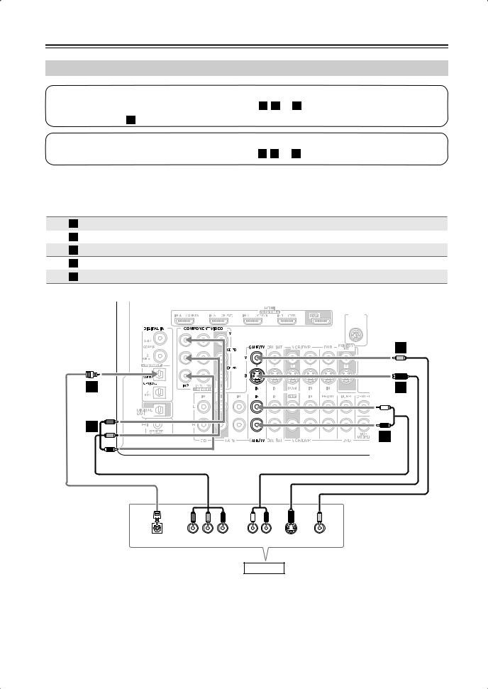
Connecting Your Components—Continued
Connecting a Game Console
Step 1: Video Connection
Choose a video connection that matches your game console ( A , B , or C ), and then make the connection. If you use connection A , you must connect the AV receiver to your TV with the same type of connection.
Step 2: Audio Connection
Choose an audio connection that matches your DVD player ( a , b , or c ), and then make the connection.
•With connection  , you can listen to and record audio from your game console or listen in Zone 2.
•To enjoy Dolby Digital and DTS, use connection  . (To record or listen in Zone 2 as well, use
  and
and  .)
.)
Connection |
AV receiver |
Signal flow |
Game console |
Picture quality |
A |
COMPONENT VIDEO IN 2 |
|
Component video output |
Best |
B |
GAME/TV IN S |
|
S-Video output |
Better |
C |
GAME/TV IN V |
|
Composite video output |
Standard |
a |
GAME/TV IN L/R |
|
Analog audio L/R output |
|
b |
DIGITAL OPTICAL IN 1 |
|
Digital optical output |
|
|
|
|
SIRIUS |
AM |
|
|
|
|
|
|
|
|
ANTENNA |
|
|
|
|
|
FMC |
|
|
|
|
75 |
b |
B |
A |
a |
|
|
|
|
L |
|
R |
|
OPTICAL |
Y |
PB |
PR |
AUDIO |
S VIDEO |
VIDEO |
OUT |
COMPONENT VIDEO OUT |
OUT |
OUT |
OUT |
||
Game Console
30
Loading...