


IN2114
Table of contents
 Loading...
IN2112, IN2114, IN2116
010-0735-02
DISPERINDAG No. 0287/1.824.51/09.0
Regulatory models: V2000, M2100

Declaration of Conformity
Manufacturer: InFocus Corporation, 13190 SW 68th Parkway, Portland, Oregon
97223-8368 USA
We declare under our sole responsibility that this pr
following directives and norms:
EMC Directive 2004/108/EC
EuP Directive 2005/32/EC
EMC: EN 55022
EN 55024
EN 61000-3-2
EN 61000-3-3
Low Voltage Directive 2006/95/EC
Safety: IEC 60950-1:2005, MOD
ojector conforms to the
Trademarks
Apple, Macintosh, and PowerBook are trademarks or registered trademarks of
Apple Computer, Inc. IBM is a tra demark or registered trademark of International
Business Machines, Inc. Microsoft, PowerPoint, and Windows are trademarks or
registered trademarks of Microsoft Corporation. Adobe and Acrobat are trademarks
or registered trademarks of Adobe Systems Incorporated. DLP® and the DLP logo
are registered trademarks of Texas Instruments and BrilliantColor™ is a trademark
of Texas Instruments. InFocus, In Focus, and INFOCUS (stylized) are either
registered trademarks or trademarks of InFocus Corporation in the United States
and other countries.
FCC Warning
This device complies with part 15 of the FCC Rules. Operation is subject to the
following two conditions: (1) This device may not cause harmful interference, and
(2) this device must accept any interference received, including interference that
may cause undesired operation.
NOTE:
Class B digital device, pursuant to part 15 of the FCC Rules. These limits are
designed to provide reasonable protection against harmful interference in a residential installation. This equipment generat
energy and, if not installed and used in accordance with the instruct ions, may ca use
This equipment has been tested and found to comply with the limits for a
es, uses and can radiate radio frequency
harmful interference to radio communications. However, there is no guarantee that
interference will not occur in a particular installation. If this equipment does cause
harmful interference to radio or television reception, which can be determined by
turning the equipment off and on, the user is encouraged to try to correct the interference by one or more of
--Reorient or relocate the receiving antenna.
--Increase the separation between
--Connect the equipment into an outlet on a circuit different from that to which the
receiver is connected.
--Consult the dealer or an experienced radio/TV technician for help.
Changes or modifications to th
InFocus Corp. may void the user’s authority to operate the equipment.
the following measures:
the equipment and receiver.
is equipment that are not expressly approved by
Canada
This Class B digital apparatus complies with Canadian ICES-003.
Cet appareil numérique de la classe B
Canada.
est conforme à la norme NMB-003 du
Agency Approvals
cMETus
Other specific Country Approvals may apply
This document applies to regulatory
Input ratings: AC 100-2
InFocus reserves the right to alter product of
without notice.
40V, 2.5A, 50-60Hz
model V2000 and M2100.
. Please see product certification label.
ferings and specifications at any time
1

Table of Contents
Introduction 4
Positioning the projector 6
Connecting power 8
Connecting a computer source 8
Displaying an image 10
Connecting a video device 12
Video device connections 12
Shutting down the projector 14
Troubleshooting your setup 14
Using the remote control 22
Using the audio 23
Using the keypad buttons 24
Optimizing computer images 24
Presentation features 24
Optimizing video images 25
Customizing the projector 25
Dynamic Messaging 25
Using the menus 26
Using Network Functions (IN2114 & IN2116 only) 33
Using LitePort (IN2114 & IN2116 only) 37
Maintenance 40
INDEX 43
Ceiling Mount 7
Optional computer connections 9
Adjusting the image 11
Basic Picture menu 27
Advanced Picture menu 28
Setup menu 29
Status and Service menu 32
Help 32
Cleaning the lens 40
Replacing the projection lamp 41
Using the security lock 42
2
Important Operating Cons
5
’ / 1.5 m
8
’
/2.4m
2’ / 0.6 m
iderations for Safety
• Refer to this guide for proper startup and shutdown procedures.
• Follow all warnings and cautions in this manual and on the projector
.
• Place the projector in a horizontal position no greater than 8 degrees off axis.
• Locate the projector at least 4' (1.2m) away from any heating
• Do not block ventilation opening
s. Locate the projector in a well-ventilated
or cooling vents.
area without obstructions to intake or exhaust vents. Do not place the projector
on a tablecloth or other soft covering that may block the vents.
• Do not place the projector in direct sunlight, humid, greasy or dusty places or
in places where the projector may come into contact with smoke or steam.
• Do not look directly into the lens while the projector is being used.
• Do not drop the projector.
• Do not spill liquid on the projector. Spilled
• Use the power cord provided. Connect the power
liquid may damage the projector.
cord to a receptacle with a
protective safety (earth) ground terminal. A surge-protected power strip is
recommended.
• Do not overload wall outlets.
• When disconnecting the power cord, hold
the plug, not the cord.
• Wash hands after handling the cables supplied with this product.
• The projector remote control uses batteries. Make sure the batteries’ polarity
(+/-) is aligned correctly
. Dispose of used batteries in accordance with local
disposal laws.
• Use an InFocus approved ceiling mount kit for proper fitting, ventilation and
installation. The warranty does not cover any damage caused by use of nonapproved ceiling mount kits or by installing in an improper location.
• When the projector is ceiling mounted, wear protective eyewear to prevent eye
injury before opening lamp door.
• Refer all service to qualified service personnel. Servicing your own projector
can be dangerous to you and will void the warranty.
• Only use replacement parts specified by In
may result in fire, electrical shock, or injury, and may void the warranty
Focus. Unauthorized substitutions
• Only genuine InFocus lamps are tested for use in this projector. Use of non
InFocus la
mps may cause electrical shock and fire, and may void the projector
warranty.
Hg – Lamp contains mercury. Manage in accordance with local
•
disposal laws. See www.lamprecycle.org.
• The projector uses a high-pressure mercury glass lamp. The lamp may fail
prematurely, or it may rupture with a popping sound if jolted, scratched, or
handled while hot. The risk of lamp failure or rupture also increases as the
lamp age increases; please replace the lamp when you see the “Replace Lamp”
message.
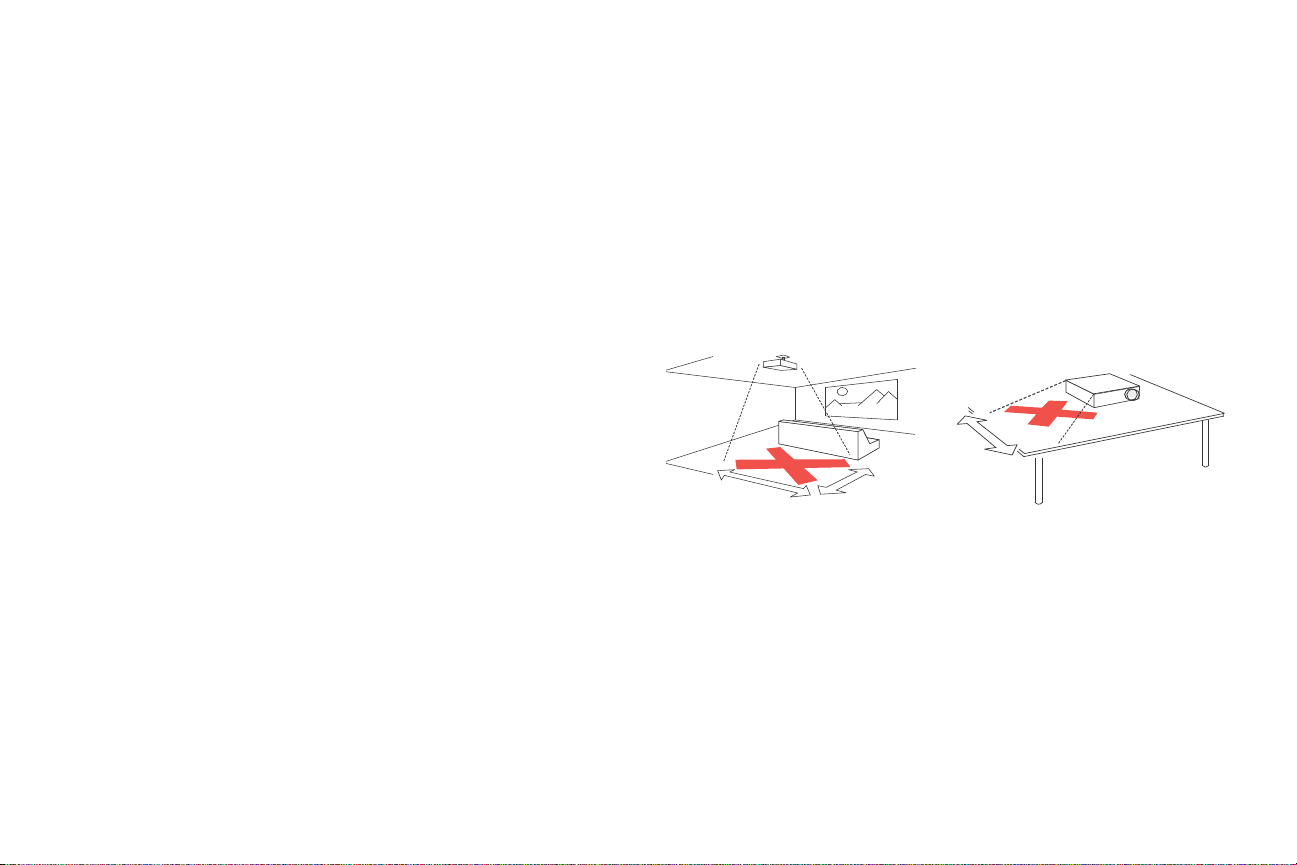
• In the unlikely event of a lamp rupture, particles may exit through the p
vents. Keep people, food, and drinks out of the "keep out" area under and
around the projector, as indicated by the "X" areas below.
Follow these instructions to help ensure image quality and lamp life over the life of
the projector. Failure to follow these instructions may affect the warranty. For complete details of the warranty, see the Warranty Booklet.
rojector
3
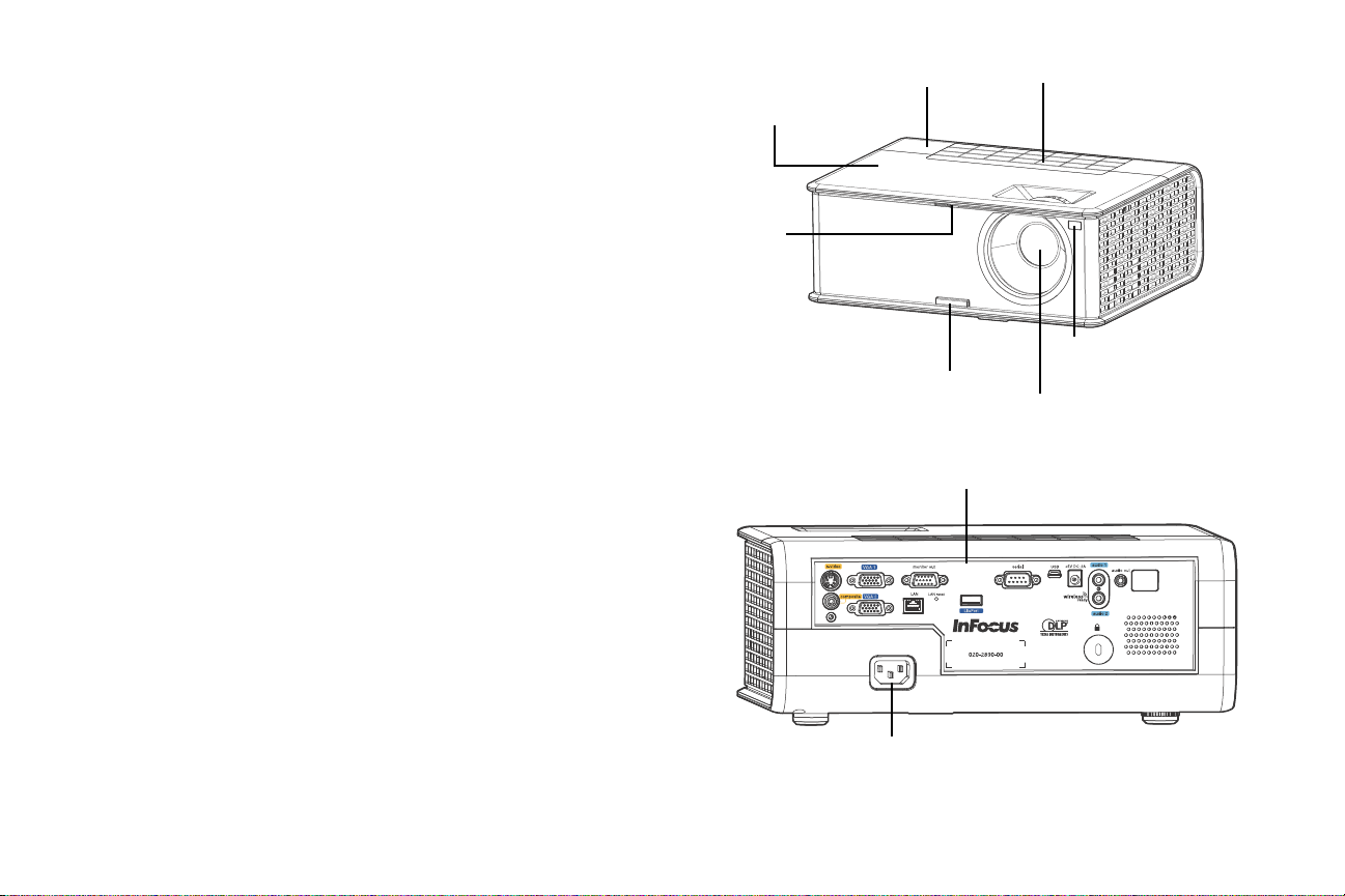
Introduction
LiteTouc h keypad
Lens
Remote control
receiver (IR)
Top fr ont cover /
Lamp access panel
Top rear cover
Elevator foot
release button
Sliding lens
cover button
Connector panel
Power cord
connector
Your new digital projector is simple to connect, easy to use, and straightforward to
maintain. It is a versatile projector that is flexible enough for business presentations
and home video viewing, too. The IN2112 has native SVGA 800 x 600 resolution,
the IN2114 has native XGA 1024x768 resolution, and the IN2116 has WXGA
1280x800 resolution. This guide applies to both products. They are compatible with
a wide variety of computers and video devices.
Product specifications
To read the latest specifications on your multimedia projector, be sure to visit our
support website at www.infocus.com/support, as specifications are subject to
change.
Online registration
Register your projector on our website at www.infocus.com/register to activate
your warranty and receive product updates, announcements, and registration
incentives.
Included Items
The standard accessories which came with your projector are listed in the included
Quick Start poster.
Optional Accessories
Optional accessories include the Commander-2 remote, ceiling mount, and
LiteShow II. These items and other accessories can be found on our website at
www.infocus.com or at your local dealer.
4
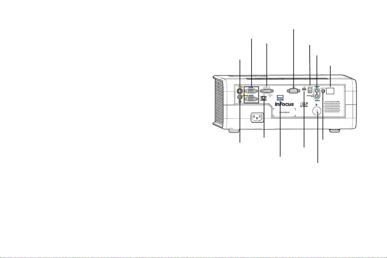
Connector panel
IR Sensor
S-video
Monitor out
VGA
RS-232
5V DC
output
Composite
video
Security lock
Audio in
Audio out
LAN
Liteport
USB-B
mini
The projector provides both computer and video connection options, including:
• VGA computer (2)
•S-video
• Composite video
• Separate audio inputs for video and computer
The projector also provides the following connectors:
• Monitor out, to provide an image on your desktop computer as well as on the
projection screen.
• Audio out, to provide sound for external speakers.
• 5 volt DC output
• RS-232 connector for serial control. Command co
our support website at www.infocus.com/support.
• USB-B mini for firmware upgrades and presentation control.
• IN2114 & IN2116 only: LitePort, for connecting a USB flash drive containing
JPEG image
s.
ntrol
codes are available on
• IN2114 & IN2116 only: LAN port for network control and web server.
NOTE: Only VGA video is sent to the Monitor out connector.
5 volt DC output
The coaxial 6.4mm x 2.2mm jack provides a constant 5 volt, 2 amp DC output
when the projector is on, and will also provide power when the projector is powered
off, if Network item in the Always-On Functions submenu is set to Yes. It is
designed to provide power to an InFocus LiteShow II wireless device.
5
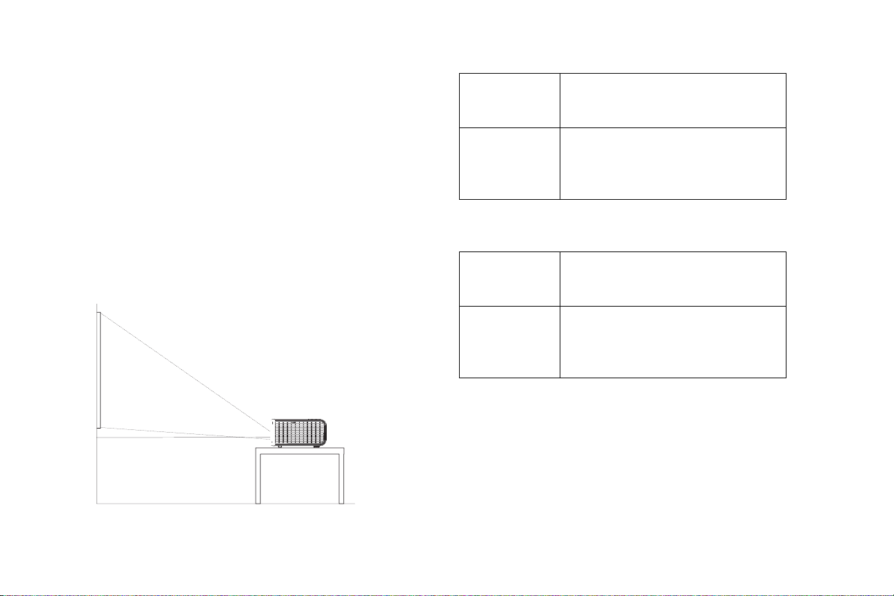
Positioning the projector
To determine where to position the projector, consider the size and shape of your
screen, the location of your power outlets, and the distance between the projector
and the rest of your equipment. Here are some general guidelines:
• Position the projector on a flat surface at a right angle to the screen. The
projector must be at least 4.9’ (1.5m) from the projection screen.
• Position the projector within 10’ (3m) of your power source
(1.8m) of your video device (unless you purchase extension cables). T o en sure
adequate cable access, do not place the projector within 6” (.15m) of a wall or
other object.
• Position the projector to the desired dist
ance from the screen. The distance
from the lens of the projector to the screen, the zoom setting, and the video
format determine the size of the projected image.
• The image exits the projector at a given angle. This image offset is 115%. This
means that for an image 10’ high, the bottom of the image will be 1.15’ above
the center of the lens.
and within 6’
Table 1: IN2112 (SVGA) and IN2114 (XGA)
Range of distance to the screen for a given screen size
Distance to screen
Diagonal Screen
Size (inches/m)
Minimum
distance (feet/m)
Maximum Distance
(feet/m)
60”/1.52m 6.48'/1.98m 7.80'/2.38m
80”/2.03m 8.64'/2.63m 10.40'/3.17m
90”/2.29m 9.72'/2.96m 11.70'/3.57m
150”/3.81m 16.20'/4.94m 19.50'/5.94m
Table 2: IN2116 (WXGA)
dist
Range of
Diagonal Screen
Size (inches/m)
ance to the screen for a given screen size
Distance to screen
Minimum
distance (feet/m)
Maximum Distance
(feet/m)
60”/1.52m 6.21’/1.89m 7.74’/2.36m
80”/2.03m 8.34’/2.54m 10.36’/3.16m
90”/2.29m 9.40’/2.86m 11.68’/3.56m
150”/3.81m 15.77’/4.81m 19.55’/5.96m
6
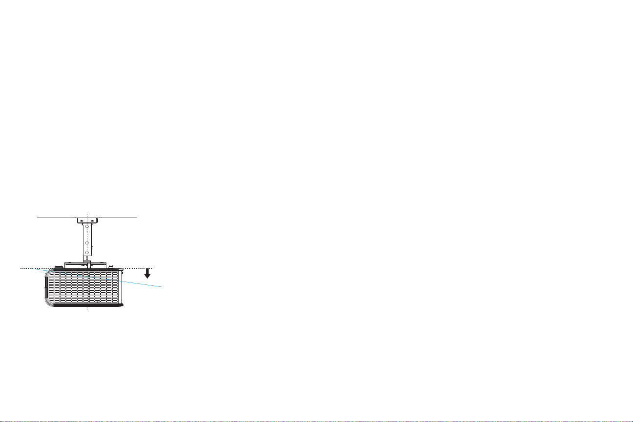
Ceiling Mount
8º
If you wish to install the projector on the ceiling:
• W e strongly recommend using InFocus approved ceiling mounts f or p roper fitting, ventilation and installation. Refer to the installation guide that comes
with the InFocus Ceiling Mount Kit (p/n SP-CEIL-UNIV) for more information. The warranty does not cover any damage caused by use of non -approved
ceiling mount kits or by
• The ceiling must be strong enough to support the p
must be in accordance with any local building codes. Consult your dealer for
more information.
• Maximum supported physical pitch is +/-8º.
• Maximum supported physical horizontal roll is +/-8º.
• Keep all adjacent surfaces 3” (76mm) from sides, front an
(22mm) from the bottom of projector to preserve required airflow around the
projector.
installing in an improper location.
rojector and the installation
d rear and .87”
7
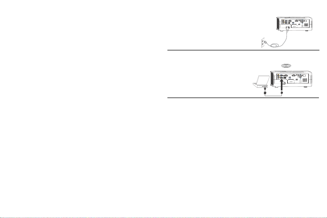
Connecting power
Connect power cord
Connect computer cable
Connect the black power cord to the Power connector on the rear of the projector
and to your electrical outlet. The Power light on the Status Indicator Panel (page 14)
turns amber.
NOTE: Always use the power
cord that shipped with the projector.
Connecting a computer source
VGA connection
Connect one end of the provided computer cable to the VGA 1 or VGA 2 connector
on the projector and the other to the VGA connector on your computer. If you are
using a desktop computer, you will need to disconnect the monitor cable from the
computer’s video port first (you can connect this monitor cable to the Monitor Out
connector on the projector, see next page).
8
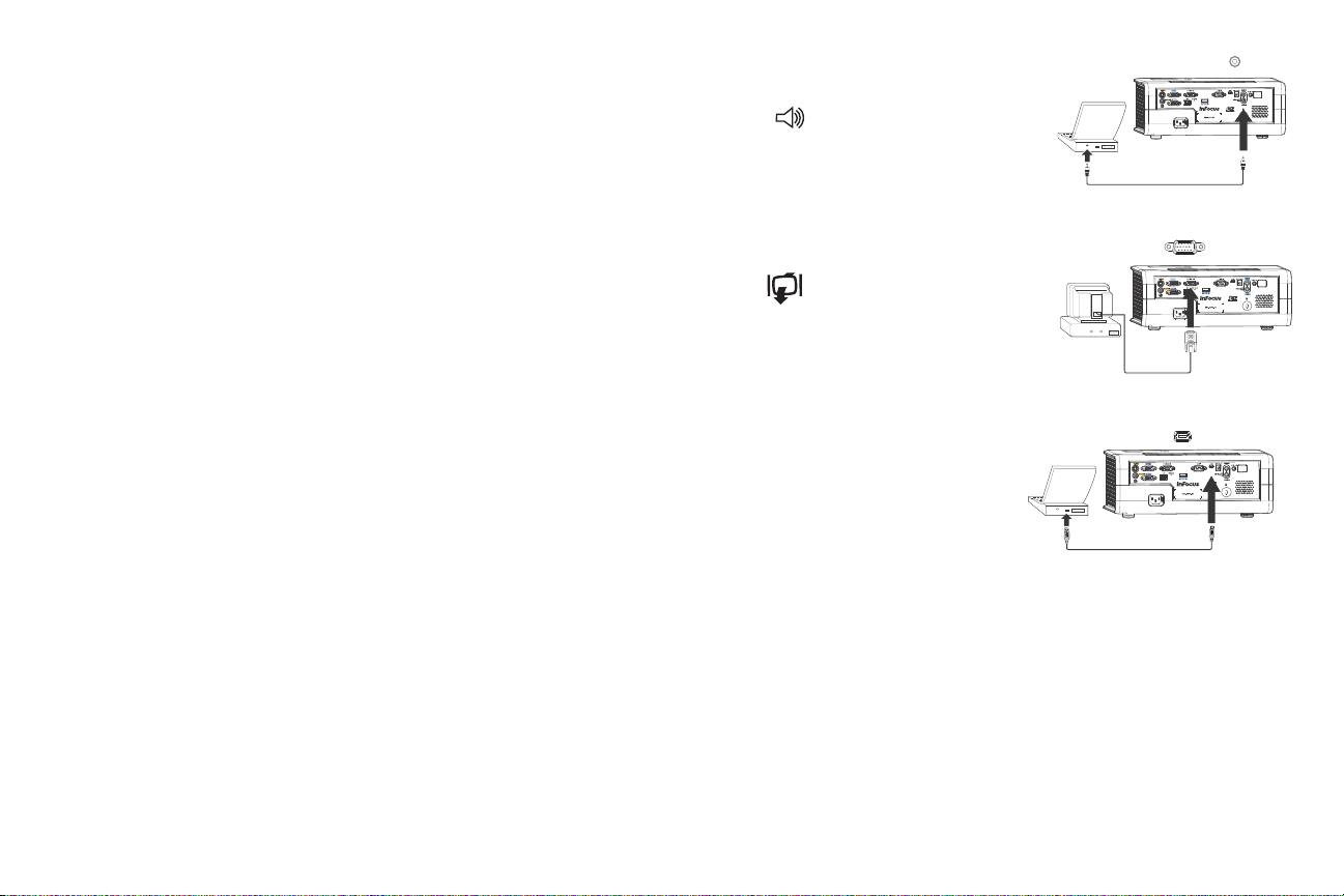
Optional computer connections
Connect audio cable
Connect monitor cable
Connect USB cable
To get sound from the projector, connect an audio cable (optional cable, not
included) to your computer and to the Audio 1 or Audio 2 connector on the
projector. (Default settings are as follows: Audio 1 is used with VGA 1 and VGA 2;
Audio 2 is used with S-video and composite.) You can also assign a your source to a
different audio in connector, see page 23 and page 30
adapter.
If you are using a desktop computer and want to see the image on your computer
screen as well as on the projection screen, connect the computer’s monitor cable to
the Monitor Out connector on the projector.
. You may also need an
NOTE: Only VGA video is sent to the Monitor out connector
.
To advance slides in a PowerPoint presentation using the remote control, plug a
USB cable between the projector’s
USB
connector and your computer. Then press
the up and down arrow buttons on the remote control to move through your slides.
o
IN2114 & IN2116 only: T
display a presentation from a USB flash drive, see the
Using LitePort section on page 37. This feature eliminates the need for a computer
source and can be integrated with common wall
plates and conference room input/
output panels.
9
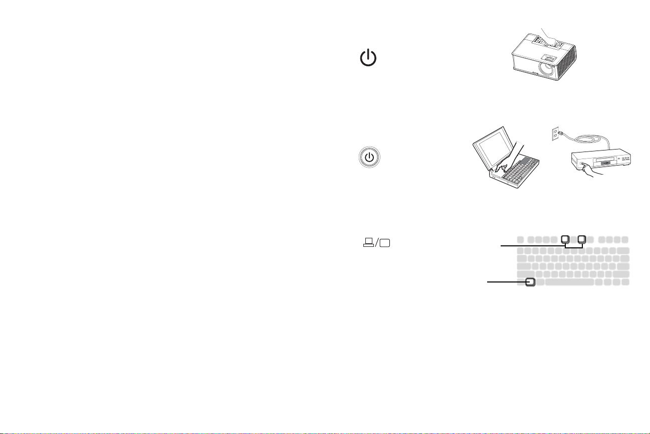
Displaying an image
Press Power button
Turn on computer or
video device
Activate laptop’s external port
Monitor key or
LCD/CRT key
Fn key
Touch the Power button on the keypad or the remote.
The Power button blinks green and t
start up screen will display and the Power button will become solid green. It can
take a minute for the image to achieve full brightness.
No start up screen? Get help
Slide the lens cover to the side, if it is covering the lens.
Turn on your computer or video device.
The image should appear on the
button on the projector’s keypad or remote.
If you are using a VGA cable to connec
If using a laptop, make sure its external video p
he fans start to run. When the lamp turns on, the
o
n page 15.
projection
screen. If it doesn’t, press the Source
t
your computer to the projector:
ort is active.
Many laptops do not automatically turn
on their external video port when a projector is connected. Usually a key combination like Fn + F8 or CR T/LCD key turns the
external display on and off. Locate a function key labeled CRT/LCD or a function
key with a monitor symbol. Press Fn and the labeled function key simultaneously.
Refer to your laptop’s documentation for more information about your laptop’s key
combination or go to the InFocus website at: http://www.infocus.com/Support/
LaptopActivation.aspx.
No laptop image? T
ry pressing the Auto Image button on the keypad.
10
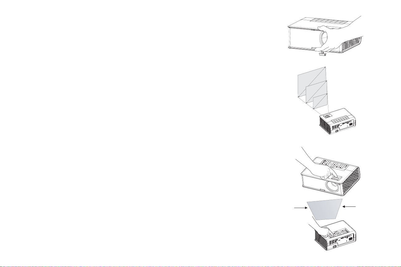
Adjusting the image
Adjust height
Adjust distance
Adjust zoom and focus
Adjust keystone
If necessary, adjust the height of the projector by pressing the elevator foot release
button to extend the foot.
Rotate the elevator feet for granular adju
stment of
placing your hands near the hot exhaust vent at the side of the projector.
the projector’s height. Avoid
A void placing your hands near the hot exhaust vent
at the side of the projector.
Position the projector to the desired distance from the screen at a 90 degree angle to
e screen. See page 6 for a table listing to screen sizes and distances.
th
Adjust the zoom or focus.
If the image is not square, first make sure that
the projector is perpendicular to the
screen. To reduce the size of the top edge of the image, press the top Keystone
button. To reduce the size of the bottom edge of the image, press the bottom
Keystone button.
ger
If the left or right side of the screen is lar
or smaller than the other, you can turn
the projector to the left or to the right a few degrees to square the ima ge. See page 6
for details.
Adjust the Contrast or Brightness in the
with these menu adjustments.
Basic Picture menu. See page 27 for help
11

Connecting a video device
You can connect video devices such as VCRs, DVD players, camcorders, digital
cameras, video game consoles, HDTV receivers, and TV tuners to the projector.
You can connect the audio directly to the projector to get sound from the built-in
speaker, or you can bypass the projector’s audio system and connect the audio
directly from your source to a stereo or home theater system.
You can connect the projector to most video devices
cannot directly connect the coaxial cable that enters your house from a cable or
satellite company; the signal must pass through a tuner first. Examples of tuners are
digital cable boxes, VCRs, digital video recorders, and satellite TV boxes.
Basically, any device that can change channels is considered a tuner.
Although the aspect ratio is automatically selected by th
signal input, you can change the aspect ratio, if desired. The projector’s Aspect
Ratio setting is accessed through the Resize button on the remote or through the
projector’s Basic Picture Menu. See page 27 for more information.
that can output video. You
e projector based on the
Video device connections
No video cables are provided with the projector. You can order cables from InFocus
or use your own.
Composite video connection
Plug the composite video cable’s yellow connector into the video out connector on
the video device. Plug the other yellow connector into the yellow Composite
connector on the projector.
Plug the white connector of a Mini-plug au
connector on the video device and plug the red connector into the right audio out
connector on the video device. Plug the other end of the cable into the associated
audio in connector on the projector.
Keep in mind that video output from composite connections is not as high
S-video.
dio Y-cable into the left audio out
quality as
If your video device uses a round, four-prong S-video connector, plug an S-video
cable into the S-video connector on your video device and into the S-video
connector on the projector. Use the audio cable as described above.
Keep in mind that video output from S-video connections is
component.
not as high quality as
VGA connection
If your video device has a 15-pin VGA output, plug one end of the included
computer cable into the VGA connector on your video source. This connector may
be labeled “To Monitor” on the video source. Plu g the computer cabl e into the VGA
1 or VGA 2 connector on the projector.
Component video connection
A Component to VGA adapter can be used in conjunction with the VGA connectors. Plug the component cable into the video device. Plug the other end of the component cable into the adapter and plug the adapter into the VG
connector.
Component offers the highest quality
video output.
A 1 or VGA 2
S-video connection
12
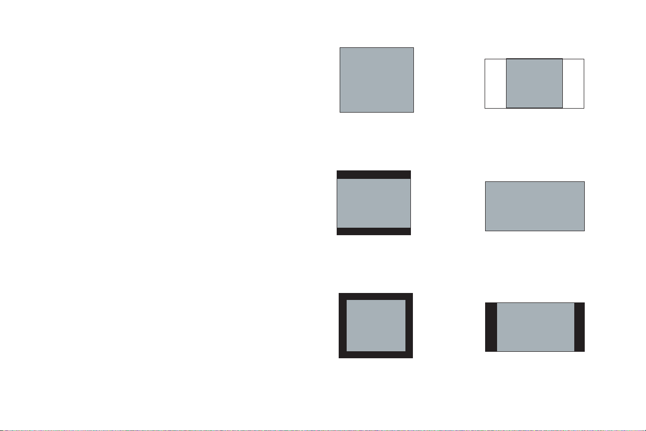
What is Aspect Ratio?
4:3 screen 16:9 screen
4:3
mode
16:9
mode
Native
mode
Aspect ratio is the ratio of the image width to image height. Standard TV screens
and older laptops are 4:3; HDTV and most DVDs are 16:9; and widescreen
computers are 16:10. If you are projecting onto a screen, the size/shape of the
screen will influence the aspect ratio you decide to use. If you are projecting onto a
blank wall, there are no screen size restrictions. What you plan to project will also
help you choose between 4:3, 16:9 or 16:10. Many TV shows are 4:3, while most
movies are 16:9.
If you have a 16:9 screen then you should select an aspect
widescreen movies or HDTV, and Native for 4:3 content. If you have a 4:3 screen
you should still use 16:9 for widescreen movies or HDTV, but you also have the
option of using either 4:3 (to fill the screen) or Native (for direct pixel mapping) for
4:3 content. Force Wide can also be enabled to automatically resize le ss common
aspect ratios to 16:10.
ratio of 16:9 for
13
Loading...