


I n f i n i t y TM
B u r n o u t F u r n a c e s OPERATOR’S MANUAL
115V, 60Hz Models

TABLE OF CONTENTS
Introduction . . . . . . . . . . . . . . . . . . . . . . . . . . . . . . . . . . . . . . . . . . . . . . . . . . . . . . . . . . . . . . . .2
Warranty . . . . . . . . . . . . . . . . . . . . . . . . . . . . . . . . . . . . . . . . . . . . . . . . . . . . . . . . . . . . . . . . . .2
Safety Instructions . . . . . . . . . . . . . . . . . . . . . . . . . . . . . . . . . . . . . . . . . . . . . . . . . . . . . . . . . . . .2
Specifications . . . . . . . . . . . . . . . . . . . . . . . . . . . . . . . . . . . . . . . . . . . . . . . . . . . . . . . . . . . . . . .3
Key Parts Identification & Explanation . . . . . . . . . . . . . . . . . . . . . . . . . . . . . . . . . . . . . . . . . . . . . .4 - 6
Installation . . . . . . . . . . . . . . . . . . . . . . . . . . . . . . . . . . . . . . . . . . . . . . . . . . . . . . . . . . . . . . . . .7 - 8
Operation . . . . . . . . . . . . . . . . . . . . . . . . . . . . . . . . . . . . . . . . . . . . . . . . . . . . . . . . . . . . . . . . .9 - 16
Program and Operate - One Stage Program . . . . . . . . . . . . . . . . . . . . . . . . . . . . . . . . . . . . . . . . . . . .9 Program and Operate - Two Stage Program . . . . . . . . . . . . . . . . . . . . . . . . . . . . . . . . . . . . . . . . . . . . .10 Program and Operate - Three Stage Program . . . . . . . . . . . . . . . . . . . . . . . . . . . . . . . . . . . . . . . . . . .11 Program and Operate - Four Stage Program . . . . . . . . . . . . . . . . . . . . . . . . . . . . . . . . . . . . . . . . . . . .12 Review a Program . . . . . . . . . . . . . . . . . . . . . . . . . . . . . . . . . . . . . . . . . . . . . . . . . . . . . . . . . . . . . . .13 Edit While a Program is Running . . . . . . . . . . . . . . . . . . . . . . . . . . . . . . . . . . . . . . . . . . . . . . . . . . . . .14 Sample Programs . . . . . . . . . . . . . . . . . . . . . . . . . . . . . . . . . . . . . . . . . . . . . . . . . . . . . . . . . . . . . . . .15
Error Codes . . . . . . . . . . . . . . . . . . . . . . . . . . . . . . . . . . . . . . . . . . . . . . . . . . . . . . . . . . . . . . . .17 - 18
Service . . . . . . . . . . . . . . . . . . . . . . . . . . . . . . . . . . . . . . . . . . . . . . . . . . . . . . . . . . . . . . . . . . .19 - 20
Field Service . . . . . . . . . . . . . . . . . . . . . . . . . . . . . . . . . . . . . . . . . . . . . . . . . . . . . . . . . . . . . . . .21 - 26
Replacement of Heating Plates . . . . . . . . . . . . . . . . . . . . . . . . . . . . . . . . . . . . . . . . . . . . . . . . . . . . . .21
Replacement of Main PC Board . . . . . . . . . . . . . . . . . . . . . . . . . . . . . . . . . . . . . . . . . . . . . . . . . . . . .23
Replacement of Thermocouple Assembly . . . . . . . . . . . . . . . . . . . . . . . . . . . . . . . . . . . . . . . . . . . . . . .25
Replacement of the Triac . . . . . . . . . . . . . . . . . . . . . . . . . . . . . . . . . . . . . . . . . . . . . . . . . . . . . . . . . . .26
Spare Parts List . . . . . . . . . . . . . . . . . . . . . . . . . . . . . . . . . . . . . . . . . . . . . . . . . . . . . . . . . . . . . .27 - 28
Program Cards . . . . . . . . . . . . . . . . . . . . . . . . . . . . . . . . . . . . . . . . . . . . . . . . . . . . . . . . . . . . . .29 - 30
1
INTRODUCTION
Thank you for purchasing an Infinity Burnout Furnace.
We have designed and manufactured this furnace using the latest in microcomputer technology to give you many years of dependable service. The controls on your new Infinity are different from those you may be used to on an ordinary burnout furnace. To ensure that your Infinity Burnout Furnace gives you the highest level of service, review and follow the guidelines outlined in this Operator’s Manual.
WARRANTY
This Jelrus equipment is warranteed to be free from defects in material and workmanship from the date of installation for a period of twelve months (the muffle on our furnaces are waranted for 24 months).
Any item returned to our factory in Hicksville, New York, through an authorized dealer, will be repaired or replaced at our option at no charge provided that our inspection shall indicate it to have been defective. Dealer, labor, shipping and handling charges are not overed by this warranty.
This warranty does not apply to damage due to shipping, misuse, careless handling or repairs by other than authorized service personnel. Jelrus International is not liable for indirect or consequential damage or loss of any nature in connection with this equipment.
This warranty is in lieu of all other warranties expressed or implied. No representative or person is authorized to assume for us any liability in connection with the sale of our equipment.
SAFETY INSTRUCTIONS
Use of the Infinity furnace not in conformance with the instructions specified in this manual may result in premture failure of the unit.
WARNING: To prevent fire or electrical shock, do not expose this appliance to rain or moisture.
ATTENTION USERS:
This symbol alerts the user that important Operating and Maintenance instructions have been included with the unit. Read carefully to avoid any problems.
This symbol warns the user to use caution surface is hot.
Do Not Attempt Internal Service
The interior of the Main Assembly is only accessible by removing hardware with tools and should only be opened and serviced by qualified technicians. Since the interior of the unit may contain high voltage and dangerous components, failure to heed this warning may result in equipment damage, personal injury and/or death.
Please call Jelrus between 9:00 a.m. and 5:00 p.m. (EST) for service information.
2

SPECIFICATIONS
|
|
|
|
INFINITY M |
|
INFINITY L |
|
|
|
|
|||||
|
Electrical |
|
115V |
|
60Hz |
1150W |
115V |
60Hz |
1610W |
||||||
|
|
|
|
|
|
|
|
|
|
|
|
|
|
||
|
Capacity |
|
|
8-1 3/4” rings or 2-3” rings |
15-1 3/4” rings or |
|
|
|
|||||||
|
|
|
|
|
|
|
|
|
5-1 3/4” rings and 3-3” rings |
||||||
|
|
|
|
|
|
|
|
|
|
|
|||||
|
|
|
|
|
|
|
|
|
|
|
|
|
|
|
|
|
Overall |
|
10-3/4”W x 13-7/8”D x 18-3/4”H |
14-1/2”W x 14-3/8”D x 18-3/4”H |
|||||||||||
|
Dimensions |
|
|||||||||||||
|
|
(27.3cm x 35.2cm x 47.6cm) |
(36.8cm x 36.5cm x 47.6cm) |
||||||||||||
|
|
|
|
||||||||||||
|
|
|
|
|
|
|
|
|
|
|
|
|
|
|
|
|
Heating |
|
5-1/2”W x 5-1/4”D x 5-1/8”H |
9-1/8”W x 5-1/4”D x 5-1/8”H |
|||||||||||
|
Chamber |
|
|||||||||||||
|
|
(14.0cm x 13.3cm x 13.0cm) |
(23.2cm x 13.3cm x 13.0cm) |
||||||||||||
|
Dimensions |
|
|||||||||||||
|
|
|
|
|
|
|
|
|
|
|
|
|
|
||
|
INFINITY M AND L |
|
|
|
|
|
|
|
|
||||||
|
|
|
|
|
|
|
|
|
|
|
|
|
|
|
|
|
|
Number of Programs |
30 |
|
|
|
|
|
|
||||||
|
|
|
|
|
|
|
|
|
|
|
|
|
|
|
|
|
|
|
|
|
|
|
|
0 - 99 hours |
|
|
|
|
|
|
|
|
|
NIGHT TIME |
|
|
|
|
|
|
|
|
|
|
|||
|
|
(DELAY START) |
|
|
|
Note: This is the time required for the program to be completed |
|||||||||
|
|
|
|
|
|
|
|
|
and ready to cast. |
|
|
|
|
|
|
|
|
|
|
|
|
|
|
|
|
|
|
|
|||
|
|
|
|
|
|
|
|
|
|
|
|
|
|||
|
|
|
|
|
|
|
|
|
|
|
|
|
|
|
|
|
|
|
|
|
|
|
|
|
a) 1 - 30°F/min. (1 - 17°C/min.) |
|
|
|
|
||
|
|
HEAT RATE* |
|
|
|
|
|
|
|
|
|||||
|
|
(Stage 1) |
|
|
|
|
|
b) “FULL” Stage heats at the maximum rate attainable. |
|
|
|
||||
|
|
|
|
|
|
|
|
|
|
|
|
|
|||
|
|
|
|
|
|
|
|
|
|
|
|
|
|
|
|
|
|
|
|
|
|
|
|
|
|
|
|
|
|||
|
|
|
|
|
|
|
|
|
a) 1 - 30°F/min. (1 - 17°C/min.) |
|
|
|
|
||
|
|
HEAT RATE* |
|
|
|
|
|
|
|
|
|
||||
|
|
(Stages 2, 3, & 4) |
|
|
b) “FULL” Stage heats at the maximum rate attainable. |
|
|
|
|||||||
|
|
|
|
|
|
|
|
|
c) “NO” Stage is not used. |
|
|
|
|
|
|
|
|
|
|
|
|
|
|
|
d) “COOL” Stage cools down to the programmed temperature. |
|
|||||
|
|
|
|
|
|
|
|
|
Note: If “NO” is selected for a stage, that stage and all subsequent |
|
|||||
|
|
|
|
|
|
|
|
|
|
||||||
|
|
|
|
|
|
|
|
|
stages will not be used. The furnace, therefore, can be used for one, |
|
|||||
|
|
|
|
|
|
|
|
|
two, three or four stage operation. |
|
|
|
|
||
|
|
|
|
|
|
|
|
|
|
||||||
|
|
TEMPERATURE |
|
a) Stage 1: |
150°F - 2012°F (66°C - 1100°C) |
|
|
|
|||||||
|
|
|
|
|
|
|
|
|
b) Stage 2, 3, 4: |
100°F - 2012°F (38°C - 1100°C) |
|
|
|
||
|
|
|
|
|
|
|
|
|
|
|
|
|
|
|
|
|
|
|
|
|
|
|
|
0 - 4 hours |
|
|
|
|
|
|
|
|
|
HOLD TIME |
|
|
|
|
|
|
|
|
|
|
|
||
|
|
|
|
|
|
|
|
|
|
|
|
|
|
|
|
|
|
|
|
|
|
|
|
|
|
|
|
|
|
|
|
*Programmable heat rates. Actual heat rate at high temperatures may be lower depending upon furnace load and electrical voltage.
ENVIRONMENTAL CONDITIONS
- Indoor use
- Altitude up to 2000 m
- Temperature 5°C to 40°C (41°F to 104°F)
- Maximum relative humidity 80% for temperatures up to 31°C (88°F) decreasing linearly to 50% relative humidity at 40°C (104°F)
- Mains supply voltage fluctuations not to exceed +/- 10% of the nominal voltage
- Pollution Degree 2, Installation Category II
3

KEY PARTS IDENTIFICATION AND EXPLANATION
FRONT PANEL (Figure 1) |
|
|
|||
|
|
|
|
||
DISPLAY |
|||||
|
DESCRIPTION |
||||
|
|
|
|
|
|
1. |
NIGHT TIME |
Press to start a delayed program. The number entered is the time |
|||
|
(DELAY START) |
required for the program to be COMPLETED AND READY TO CAST. |
|||
|
|
|
When a program is running, press to display the time remaining to |
||
|
|
|
complete the program. |
||
2. |
START / STOP |
Press to start or stop a program. |
|||
3. |
|
|
Press to increase a number. The longer the button is pressed, the |
||
|
|
|
faster the numbers change. |
||
4. |
|
|
Press to decrease a number. The longer the button is pressed, the |
||
|
|
|
faster the numbers change. |
||
5. |
ENTER / REVIEW |
When programming or reviewing a program in process, press to |
|||
|
|
|
advance to the next parameter. |
||
6. |
PROGRAM SELECT |
Press to select a program or to review the program currently running. |
|||
7. |
STAGE 1-2-3-4 |
While programming, the number of active stages are illuminated. In |
|||
|
|
|
the burnout process, the current STAGE flashes. |
||
8. |
°F and °C |
Identifies the temperature scale. |
|||
9. |
°/ MIN |
Identifies the heat rate. |
|||
10. HH : MM |
Indicates time. When flashing it indicates that a power failure has |
||||
|
|
|
occurred. |
||
11. Main Display |
A. The 4 digit display indicates the chamber temperature. |
||||
|
|
|
B. When programming or reviewing, indicates PROGRAM NUMBER, |
||
|
|
|
NIGHT TIME (DELAY START) (time to completion), HEAT RATE, |
||
|
|
|
TEMP and HOLD TIME. |
||
|
|
|
C. Displays special words and error codes. |
||
12. Program Status Graph |
Indicates status of the burnout process. |
||||
13. Door Interlock |
Shuts off electrical power from the heating plates |
||||
|
Safety Switch |
when the furnace door is opened. |
|||
4

KEY PARTS IDENTIFICATION AND EXPLANATION
|
Vent |
|
Tube |
|
Keep clear 6” zone |
|
around Vent Tube |
|
Heating |
|
Chamber |
|
13 |
11 |
|
|
8 |
7 |
|
12 |
Front |
|
|
|
Panel |
|
5 |
|
3 |
1 |
4 |
Figure 1
INFINITY M AND L IDENTIFICATION
5
KEY PARTS IDENTIFICATION AND EXPLANATION
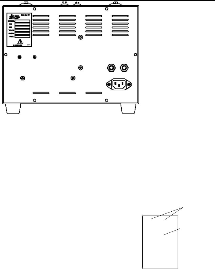
LOWER BACK PANEL (Figure 2)
DISPLAY |
DESCRIPTION |
|
1. |
Power Cord |
AC power cords are provided to correspond to receptacles that are available |
|
|
in a specific country. |
2. |
Circuit Breaker |
Protects circuitry from electrical overload. |
|
|
- Black button will “pop out” if overload is present. |
|
|
- To reset, wait one minute and push black button into body of |
|
|
circuit breaker. |
Figure 2
INFINITY LOWER BACK PANEL
2
IEC RECEPTACLE
6

INSTALLATION
UNPACK AND SET-UP
1.Unpack the contents of the box. Remove the following materials:
A.Vent Tube - Remove from bubble wrap and insert in hole on top of furnace.
B.Calibration Table Kit - Remove plastic bag containing two tablets and save for future use.
C.Burnout Tray - Remove tray(s) from bubble wrap and install on the floor of the chamber.
2.Place the furnace in position allowing a minimum of 10 inches (25.4 cm) of air space on all sides.
3.Plug the power cord into a wall receptacle. First connect the power cord located on the rear of the furnace. For large furnaces a dedicated 20A, 115V circuit terminated with a NEMA 5-20 R type receptical is required. For medium furnaces a dedicated 15A, 115V curcuit terminated with a NEMA 5-15 R type receptical is the minimum requirement. A 20 AMP circuit is recommemnded.
4.The furnace is now ready for operation.
CAUTIONS:
DO NOT BLOCK VENT HOLE ON TOP OF THE FURNACE. Hot gases are vented through this hole.
TO SET TEMPERATURE SCALE (Figure 1)
115V furnaces are pre-set in degrees Fahrenheit.
1.Turn the power switch on. (If the furnace is already on, be sure it is in the idle mode - no program is running.) The chamber temperature appears on the Main Display and the °F light goes on.
2. Press |
at the same time. The degree light switches to the opposite temperature scale. |
VENTING INSTRUCTIONS
Vent fans must have a minimum capacity of 100 cubic feet per minute for each burn out furnace.
If a common hood is used for more than one burn out furnace, fan capacity must be 100 cubic feet per minute for each square foot of hood opening.
All hoods, vent pipe and ducting components must be constructed of non combustable materials and be installed in accordance with local building codes.
Maximum expected exhaust temperature is 1800°F (980°C).
Maximum expected exhaust waste heat is 5,100 BTU’S / Hour or 1,000 Watts.
7

INSTALLATION
TO TURN THE “BEEP” ON AND OFF (Figure 1)
When a program is completed, 20 "beeps" sound every 15 minutes to remind the operator that the material is ready to cast.
1. |
Be sure the Infinity is in the idle mode - no program us running. |
|
2. |
Press and (while holding) press PROGRAM NUMBER to display the status of the "beep." |
|
|
"ON" indicates the beep is active. "OFF" indicates the beep is inactive. |
|
3. |
Use either of the |
to turn the "beeps" on or off. |
4.To return to the idle mode, wait 7 seconds or press STOP / START twice. (If STOP / START is pressed once, cycle starts.)
8

OPERATION
PROGRAM AND OPERATE - ONE STAGE PROGRAM (Figure 1)
1. |
Turn the power switch on. |
|
|
2. |
Press PROGRAM NUMBER. Use |
to display the desired program number (P1 - P30). |
|
3. |
Press ENTER / REVIEW to select the displayed PROGRAM NUMBER. STAGE 1 and NIGHT TIME |
||
|
(DELAYED START) lights turn on. Enter |
to set the time required for the program to be completed and |
|
|
ready to cast (1 - 99hrs). |
|
|
4. |
Press ENTER / REVIEW. STAGE 1 light remains on, NIGHT TIME (DELAY START) light turns off and |
||
|
HEAT RATE light turns on. Enter |
to select the heat rate required from 1°F - 30°F / min |
|
|
(1oC - 17oC / min) or "FULL" for the maximum heat rate. |
||
5. |
Press ENTER / REVIEW. STAGE 1 light remains on, HEAT RATE light turns off and TEMP light turns on. |
||
|
Enter |
to select the temperature required up to the maximum of 2012°F (1100°C). |
|
6. |
Press ENTER / REVIEW. STAGE 1 light remains on, TEMP light turns off and HOLD TIME light turns on. |
||
|
Enter |
to program the time needed to hold at above temperature. (0 - 4hrs). |
|
7.For one stage, the furnace must be programmed not to use STAGE 2, 3 or 4. Follow these steps:
A.After completing step 6, press ENTER / REVIEW. STAGE 1 light turns off, STAGE 2 and HEAT RATE lights turn on.
B. Press Main Display shows ".....5, 4, 3, 2, 1, |
COOL, NO." Select "NO" to |
program the furnace not to use STAGE 2, 3 or |
4. |
8.All necessary information for this program is now entered.
9.To run the program immediately, press START / STOP.
10.To delay the start of the program to be ready to cast at the pre-set time (see Step 3), press NIGHT TIME (DELAY START).
NOTE : If NIGHT TIME (DELAY START) is pressed while a program is running, the time remaining for completion of the program will appear on the Main Display for 5 seconds.
9
 Loading...