


61-340
Table of contents
 Loading...
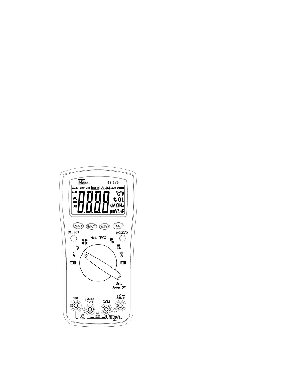
IDEAL INDUSTRIES, INC.
TECHNICAL MANUAL
MODEL: 61-340
MODEL: 61-342
Multimeter Service Information
The Service Information provides the following information:
• Precautions and safety information
• Specifications
• Basic maintenance (cleaning, replacing the battery and fuses)
• Performance test procedures
• Calibration and calibration adjustment procedures
Form Number: TM61340-2
Revision: 2. Date: November 2007
Form Number 2 TM61340-2 Rev November 2007
Form Number 2 TM61340-2 Rev November 2007
TABLE OF CONTENTS Page
Introduction 1
Precautions and Safety Information 1
Symbols 1
Safety 2
Specifications 3
General Specifications 3
Measurement Characteristics 4
Voltage Specifications 4
Current Specifications 4/5
Resistance, Diode, Continuity, Capacitance Specifications 6
Frequency, Temperature Specifications 7
Auto Power Off, Data Hold/Backlight, SELECT, RANGE, REL, Hz/DUTY, MAX/MIN 7/8
Physical and Environment Characteristics 9
Certifications and Compliances 9
Required Equipment 10
Basic Maintenance 11
Opening the Meter Case 11
Replacing the Battery 11
Replacing Fuses 12
Fuse Replacement 12
Cleaning 12
Performance Tests 13
Testing the Display 13
Testing the Voltage Function 14/15
Testing the DC Current Functions 15/16
Testing the AC Current Functions 16/17
Testing the Resistance Function 18
Testing the Capacitance, Diode, Continuity Functions 18/19
Testing the Frequency Function 20
Testing the DUTY CYCLE Function 20
Testing the Temperature Function 21
Calibration 22
Calibration Adjustment, DCV, ACV DCA and Temperature Functions 22/23
Page 1
Introduction
Warning
To avoid shock or injury, do not perform the verification tests or calibration procedures described in
the manual unless you are qualified to do so.
The information provided in this document is for the use of qualified personnel only.
Caution
The 61-340 serials contain parts that can be damaged by static discharge.
Follow the standard practices for handling static sensitive devices.
For additional information about IDEAL INDUSTRIES, INC. and its products, and services, visit IDEAL
INDUSTRIES, INC. web site at:
www.idealindustries.com
Precautions and Safety Information
Use the meter only as described in the Service Manual. If you do not do so, the protection provided by the
meter may be impaired. Read the “Safety Information” page before servicing this product.
In this manual, a Warning identifies conditions and actions that pose hazard (s) to the user; a Caution
identifies conditions and actions that may damage the meter or the test instruments.
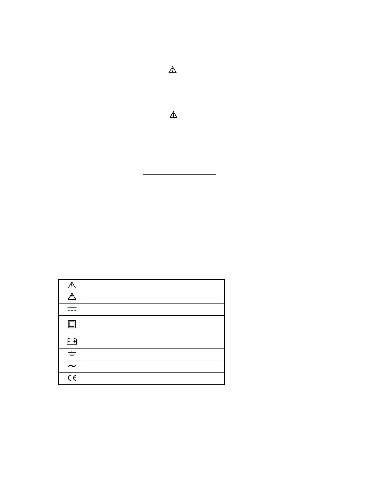
The Symbols
The symbols used on the meter and in this manual are explained in Table A.
Table A. The Symbols
Risk of electric shock
See instruction card (Caution information)
DC measurement
Equipment protected by double or reinforced
insulation
Low Battery indicator
Earth
AC measurement
Conforms to EU directives
Form Number 2 TM61340-2 Rev November 2007

Page 2
SAFETY
Review the following safety precautions to avoid injury and prevent damage to this product or any
products connected to it. To avoid potential hazards, use the product only as specified.
For operating instructions, see the 61-340 / 61-342 Digital Multimeter Instruction Manual.
CAUTION: These statements identify conditions or practices that could result in damage to the
equipment or other property.
WARNING: These statements identify conditions or practices that could result in personal injury or
loss of life.
Use proper Fuse. To avoid fire hazard, use only the fuse type and rating specified for this product.
Do not operate without covers. To avoid personal injury, do not apply any voltage or current to the
product without covers in place.
Do Not Exceed the maximum rated input limits, as marked on the meter.
Electric overload. Never apply a voltage to a connector on the product that is outside the range
specified for that connector.
Avoid electric shock. To avoid injury or loss of life, do not connect or disconnect probes or test leads
while they are connected to a voltage source.
Do not operate in wet/damp conditions. To avoid electric shock, do not operate this product in wet or
damp conditions.
Use great care when you are required to make measurements on live circuits that exceed 50V.
Form Number 2 TM61340-2 Rev November 2007
Page 3
SPECIFICATIONS
All specifications are warranted unless noted typical and apply to the 61-340 & 61-342
Stated accuracies are at 23°C±5°C at less than 75% relative humidity and without the battery indicator
displayed.
General specifications
Characteristics Description
Display count 3 3/4 digit liquid crystal display, max count 4000
Numeric update rate 2.5 times / sec
Polarity display Automatic
Over range display “OL” is displayed
Low battery indicator is indicated
Automatic power-off time Automatic power off ≈ 10minutes
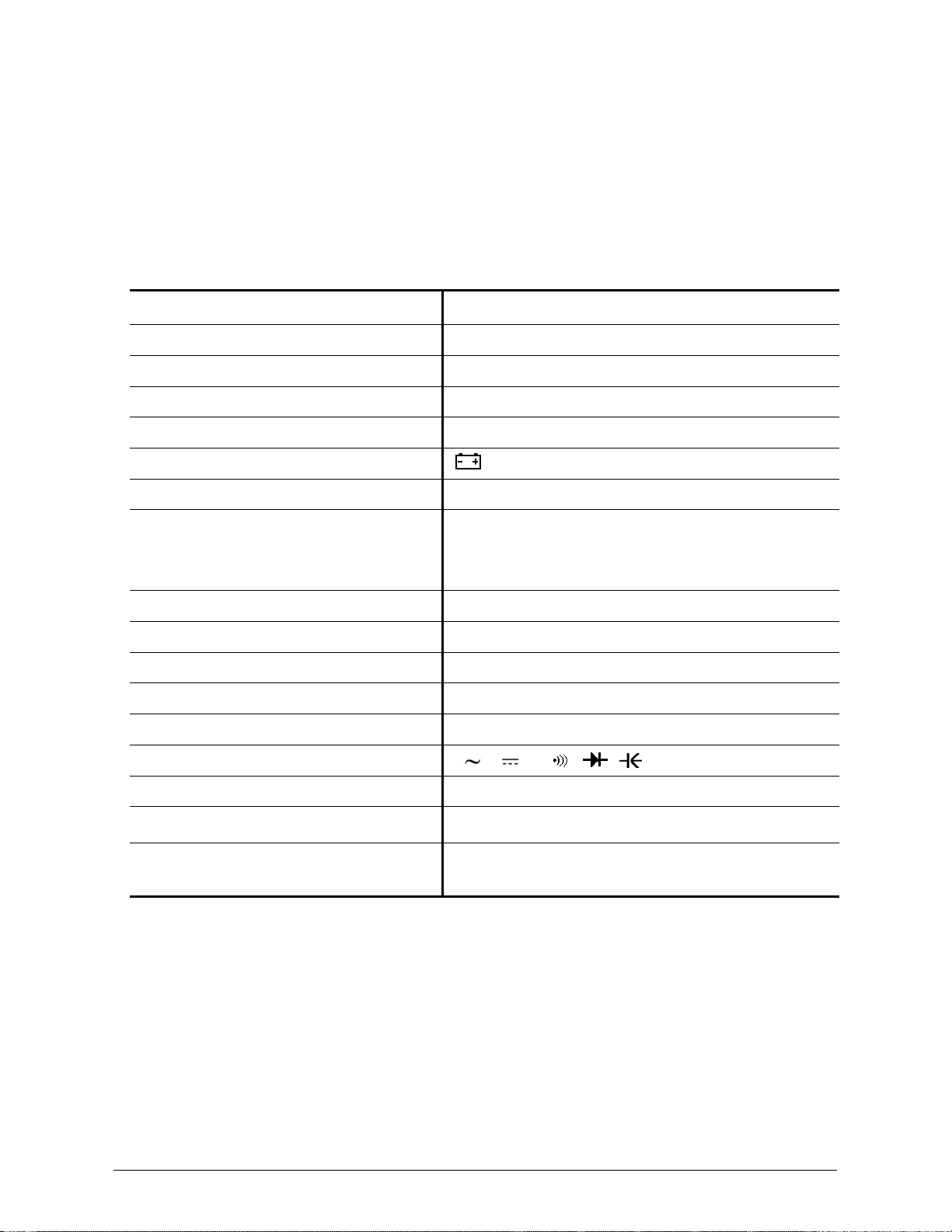
Power source
9.0V battery: types- NEDA 1604, JIS006P, IEC6F22
for both 61-340 and 61-342
*Maximum input voltage 1000Vrms CAT III between V and COM
*Maximum floating voltage
1000Vrms CAT III between any terminal and earth ground
Maximum input current 400mA between µA /mA and COM
Overload protection mA connector 500mA (250V) fast blow fuse.
Overload protection 10A connector 10A (250V) fast blow fuse.
V connector V , V , Ω, , , , Hz
µA /mA connector µA, mA, Temp
Temperature Coefficient 0.1×(Spec. Accuracy) per °C, <18°C or >28°C
Battery Life
Alkaline 9V, ≈ 200 hours for 61-340
Alkaline 9V, ≈ 150 hours for 61-342
Form Number 2 TM61340-2 Rev November 2007
Form Number 2 TM61340-2 Rev November 2007
Page 4
Measurement Characteristics
Accuracy is ±(% reading + number of digits) at 23°C ± 5°C, less than 75% R.H.
(1) DC Volts(for 61-340 / 61-342)
Range Resolution Accuracy
Over voltage
protection
400.0mV 0.1mV ±(0.8% reading + 3 digits)
4.000V 1mV
40.00V 10mV
400.0V 100mV
±(0.8% reading + 1 digits)
1000V 1V ±(1.0% reading + 3 digits)
1000VDC or 750VAC
Input Impedance: 10MΩ
(2) AC Volts (61-340/61-342)
Range Resolution Accuracy
Over voltage
protection
400.0mV 0.1mV
±(1.2%+8)
4.000V 1mV
40.00V 10mV
400.0V 100mV
1.0% + 5
750V
1V
±(1.2%+5)
1000VDC or 750VAC
Input Impedance: 10MΩ
AC Conversion Type: 61-340: Average sensing rms indication calibrated to the sine wave input.
61-342: AC conversion is True RMS responding, calibrated to a sinusoidal
waveform
Crest Factor: C.F. = Peak/RMS
For non-sinusoidal waveform, C.F. > 2 add ±1% to accuracy,
Frequency response: 40~400Hz
(3a) DC micro-amp and milli-amps (for 61-340 / 61-342)
Range Resolution Accuracy Input Protection
400.0µA 0.1μA
4000µA 1μA
±(0.8% reading + 2 digits)*
40.00mA 10μA
400.0mA 0.1mA
±(0.8% reading + 3 digits)*
500mA, 250V Fast
Blow Fuse
Overload Protection: mA Input: 500mA, 250V Fast Blow fuse. (61-340 / 61-342)

Form Number 2 TM61340-2 Rev November 2007
Page 5
(3b) DC Current (61-340 / 61-342)
Range Resolution Accuracy Input Protection
4.000A 0.001A
10.00A* 0.01A
±(1.5% reading + 5 digits)
10A, 250V Fast Blow
Fuse
Overload Protection: A Input: 10A, 250V Fast Blow fuse. (61-340 / 61-342)
*Caution
: Do not make high current measurements on the 10A scale for longer that 15 seconds. This should be
followed by a 15 minute cool down period. Exceeding 15 seconds may cause da mage to the meter and/or the test
leads.
(4a) AC micro-amp and milli-amps Current (61-340 / 61-342)
Range Resolution Accuracy Input Protection
400.0µA 0.1μA
4000µA 1μA
±(1.5% reading + 5 digits) *
1
40Hz
~ 400Hz
40.00mA 10μA
400.0mA 0.1mA
±(2.0% reading + 5 digits) *
1
40Hz
~ 400Hz
500mA, 250V Fast
Blow Fuse
Overload Protection: μA / mA Input: 500mA,250V Fast Blow fuse. (61-340 / 61-342)
(4b) AC Current (61-340 / 61-342)
Range Resolution Accuracy Input Protection
4.000A 0.001mA
10.00A* 0.01mA
±(2.5% reading + 5 digits) *
1
40Hz
~ 400Hz
10A, 250V Fast Blow
Fuse.
Overload Protection: A Input: 10A (250V) fast blow fuse.
AC Conversion Type: AC conversions are True RMS responding, calibrated to the sine wave input.
*
1
The specified accuracy is for sine wave at full scale and non-sine wave at half scale with crest factor
up to 2.
*Caution:
Do not make high current measurements on the 10A scale for longer that 15 seconds. This should be
followed by a 15 minute cool down period. Exceeding 15 seconds may cause da mage to the meter and/or the test
leads.
Page 6
(5) Resistance (for 61-340 / 61-342)
Range Resolution Accuracy
Over voltage
protection
400.0Ω *
1
0.1Ω ±(1.2% reading + 5 digits)
4.000KΩ 1Ω
40.00KΩ 10Ω
400.0KΩ 100Ω
±(1.0% reading + 2 digits)
4.000MΩ 1KΩ ±(1.2% reading + 2 digits)
40.00MΩ *
2
10KΩ ±(2.0% reading + 5 digits)
600Vrms
Open circuit Voltage: 0.44V approx.
*
1
< 5 digit of reading rolling.
*
2
< 2% of reading rolling.
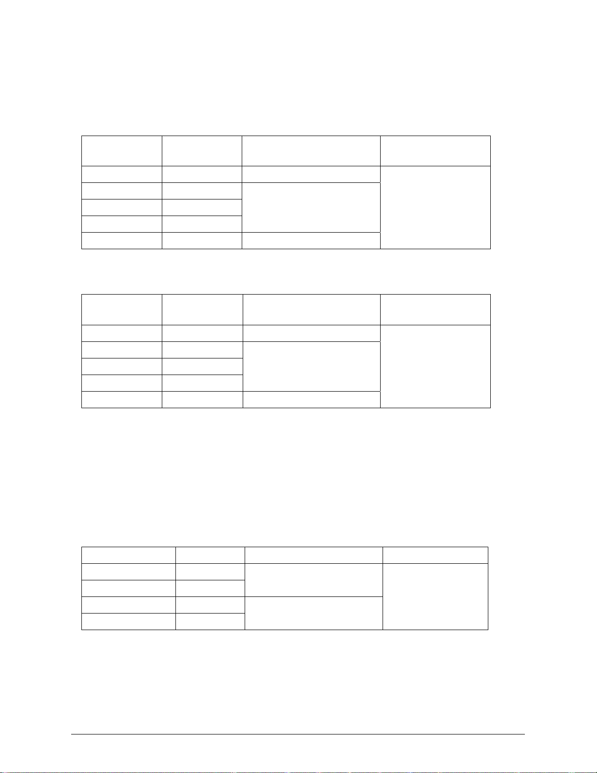
(6) Diode Check and Continuity (for 61-340 / 61-342)
Range Resolution Accuracy
Max. Test
Current
Max. Open
Circuit Voltage
1mV Not specified * <1mA, approx. 2.5V, approx.
Overload Protection: Not specified
Continuity: Built-in buzzer sounds when resistance is less than approximately 120 Ω with a response
time of approximately 100 msec.
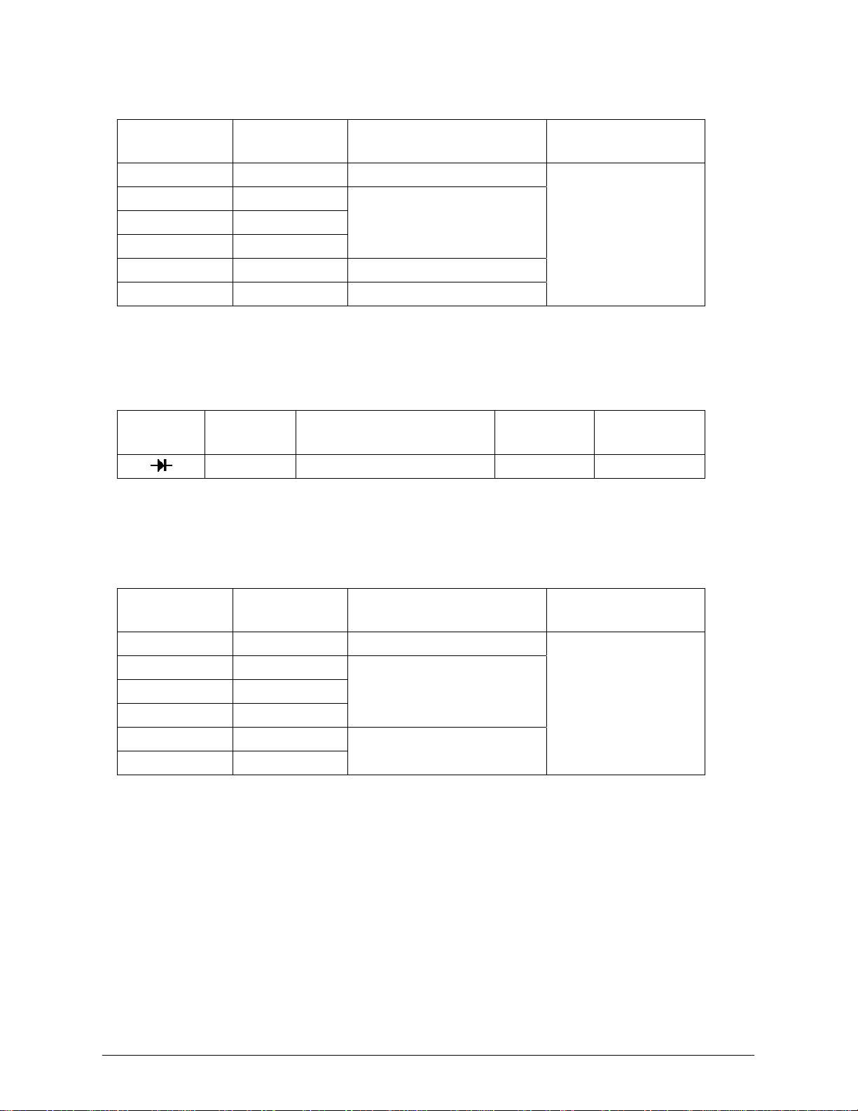
(7) Capacitance (for 61-340 / 61-342)
Range Resolution Accuracy
Over voltage
Protection
40.00nF 10pF
REL:±(3% reading + 10 digits)
400.0nF 100pF
4.000μF 1nF
40.00μF 10nF
±(3% reading + 5 digits)
400.0μF 100nF
4000μF *
1
10μF
±(20% reading + 5 digits) *
2
*
1
In this range the reading maybe rolling within specification.
*
2
Specify reading < half full scale of range.
Note: The meter selects the proper range automatically. Each measurement takes about one
second per range, Readings >40.00μF will take ≈ 8 seconds or greater
Form Number 2 TM61340-2 Rev November 2007
Loading...