


INSTRUCTION MANUAL
MARINE RADAR
MR-1000R™
(Radome type)
MR-1000T™
(Open array type; 4 kW)
MR-1000T
(Open array type; 6 kW)

SYSTEM COMPONENTS
MODEL NAME |
CRT DISPLAY |
SCANNER UNIT |
MR-1000RII |
SX-2713 (10-inch CRT) |
EX-2714 (Radome type) |
|
|
|
MR-1000TII |
SX-2779 (10-inch CRT) |
EX-2780 (Open array type; 4 kW) |
|
|
|
MR-1000TIII |
SX-2779 (10-inch CRT) |
EX-2780 (Open array type; 6 kW) |
|
|
|
SUPPLIED ACCESSORIES
• EX-2714 (Radome type unit) |
|
|
Qty. |
q System cable (OPC-1188A: 15 m) |
...................... 1 |
w Installation bolts (M10×50) .................................. |
4 |
e Installation bolts (M10×25) .................................. |
4 |
r Installation nuts (M10) ......................................... |
4 |
t Flat washers (M10) .............................................. |
4 |
y Spring washers (M10) ......................................... |
4 |
• EX-2780 (Open array type unit) |
|
|
Qty. |
q System cable (OPC-1189A: 20 m) ....................... |
1 |
w Installation bolts (M10×40) .................................. |
4 |
e Installation nuts (M10) ......................................... |
4 |
r Flat washers (M10) .............................................. |
4 |
t Spring washers (M10) ......................................... |
4 |
y Hex head wrench ................................................. |
1 |
u Cap bolts (M8×18) ............................................... |
4 |
i Dish washers (M8) ............................................... |
4 |
o Sealing washers (T) ............................................. |
4 |
!0Flat washers (M8) ................................................ |
4 |
!1Grounding terminal (R5.5-10) .............................. |
1 |
!2Ferrite bead ......................................................... |
1 |
• SX-2713/2779 (10 inch CRT display unit) |
|
|
Qty. |
q NMEA connector (FM14-8P) ................................ |
1 |
w Spare fuse (FGB 10 A) ........................................ |
1 |
e Spare fuse (FGB 5 A: for over 24 V power supply) |
|
............................................................................ |
1 |
r DC power cable (OPC-928-2) .............................. |
1 |
t Viewing hood (2363 HOOD)................................. |
1 |
y Mounting bracket (2363 ANGLE(A))..................... |
1 |
u Mounting screw knobs (2363 KNOB BOLT) ......... |
2 |
i Self-tapping screws (M6 × 30).............................. |
5 |
o Spring washers (M6) ........................................... |
5 |
!0Flat washers (M6) ................................................ |
5 |
!1Instruction manual ............................................... |
1 |
!2Operating guide ................................................... |
1 |
!3NMEA connector (FM14-7P) ............................... |
1 |
Icom, Icom Inc. and the 
 logo are registered trademarks of Icom Incorporated (Japan) in the United states, the United Kingdom, Germany, France, Spain, Russia and/or other countries.
i

FOREWORD
Thank you for purchasing Icom’s MR-1000RII/TII/TIII
MARINE RADAR.
The radar is designed especially for fishing boats. It has powerful transmission power, 10 inch CRT display and many other advanced features.
If you have any questions regarding the operation of the radar, contact your nearest authorized Icom Inc. dealer.
IMPORTANT
READ ALL INSTRUCTIONS carefully and completely before attempting to operate the marine radar.
SAVE THIS INSTRUCTION MANUAL. This manual contains important safety and operating instructions for the MR-1000RII/TII/TIII.
EXPLICIT DEFINITIONS
The following explicit definitions apply to this instruction manual.
WORD |
DEFINITION |
RWARNING |
Personal injury, fire hazard or electric |
|
shock may occur. |
CAUTION |
Equipment damage may occur. |
|
|
NOTE |
If disregarded, inconvenience only. |
No risk of personal injury, fire or |
|
|
electric shock. |
|
|
PRECAUTION
RNEVER let metal, wire or other objects touch any internal part of the radar.
RNEVER place the radar within the reach of children.
RNEVER expose the display unit to rain, salt water or any other liquids.
NEVER connect the radar to AC or more than 42 V DC. This will damage the radar.
AVOID using the radar near any magnetic materials, such as a loudspeaker or a large power transformer, as this can cause distortion of the CRT display.
AVOID placing the display unit in excessively dusty environments.
AVOID placing the display unit near heating equipment or in direct sunlight or where hot or cold air blows directly onto it.
AVOID using the scanner unit in areas where the temperature is below –25˚C (–13˚F) or above +70˚C (+158˚F). AVOID using the display unit in areas where the temperature is below –15˚C (+5˚F) or above +55˚C (+131˚F).
AVOID using strong solvents such as benzene or alcohol for cleaning the radar, as they may damage the surfaces.
BE CAREFUL!
SART signal may not be detected and may not be displayed on the screen depending on the SEA, RAIN or IR settings.
Follow the settings as below to detect the SART signal on the screen.
qSelect the screen range between 6 NM to 12 NM with [+/–]. (p. 2)
w Set the [GAIN] as high as possible. (p. 3) e Set the [SEA] to minimum. (p. 3)
r Set the [RAIN] to minimum. (p. 3) t Turn the [IR] OFF.
y Turn the [STRETCH] OFF.
ii

TABLE OF CONTENTS
SYSTEM COMPONENTS.......................................... |
i |
SUPPLIED ACCESSORIES....................................... |
i |
FOREWORD ............................................................ |
ii |
IMPORTANT ............................................................. |
ii |
EXPLICIT DEFINITIONS .......................................... |
ii |
PRECAUTION .......................................................... |
ii |
TABLE OF CONTENTS ........................................... |
iii |
1 CAUTION ............................................................. |
1 |
DANGER! HIGH VOLTAGE .................................. |
1 |
RADIATION HAZARD ........................................... |
1 |
2 PANEL DESCRIPTION .................................... |
2–5 |
■Front panel ........................................................ |
2 |
■Screen ............................................................... |
4 |
3 MENU ............................................................... |
6–7 |
■VIDEO ............................................................... |
6 |
■FUNCTION......................................................... |
6 |
■ATA (Automatic Tracking Aid) ............................. |
7 |
■INT. SETTING .................................................... |
7 |
4 BASIC OPERATION ...................................... |
8–13 |
■Checking the installation ................................... |
8 |
■Turning power ON/OFF ...................................... |
8 |
■Basic operation .................................................. |
9 |
■RAIN function ................................................... |
10 |
■SEA function..................................................... |
10 |
■OFF CENTER function..................................... |
10 |
■IR function ........................................................ |
11 |
■STRETCH function .......................................... |
11 |
■ZOOM function ................................................ |
11 |
■TRAILS function .............................................. |
12 |
■Power save function ........................................ |
12 |
■Ship speed indication ...................................... |
13 |
■Position indication ........................................... |
13 |
■Waypoint indication .......................................... |
13 |
■Long pulse function .......................................... |
13 |
■Bearing setting ................................................ |
13 |
5 DISTANCE AND DIRECTION |
|
MEASUREMENTS ....................................... |
14–16 |
■Distance measurement ................................... |
14 |
■Bearing and Distance measurement ............... |
15 |
■Advanced measurements ................................ |
16 |
6 ALARM FUNCTION ........................................... |
17 |
■Alarm zone setting ........................................... |
17 |
■Zone alarm setting ........................................... |
17 |
7 ATA (Automatic Tracking Aid) ................... |
18–20 |
■ATA (Automatic Tracking Aid) .......................... |
18 |
■ATA menu setting ............................................. |
18 |
■ATA operation .................................................. |
19 |
■Plotting marks .................................................. |
19 |
■Course and speed vector ................................ |
19 |
■Plots ................................................................ |
20 |
8 BASIC RADAR THEORY ............................ |
21– 23 |
■Side-lobe echoes ............................................. |
21 |
■Indirect echoes ................................................ |
21 |
■Multiple echoes ............................................... |
22 |
■Minimum range ................................................ |
22 |
■Blind and Shadow sectors ............................... |
23 |
■Target resolution............................................... |
23 |
9 INSTALLATION AND CONNECTIONS ........ |
24–30 |
■Connecting the units ........................................ |
24 |
■Power source requirement .............................. |
24 |
■Ground connection ........................................... |
24 |
■Installing the display unit ................................. |
25 |
■Mounting the EX-2714 scanner unit ................ |
26 |
■Wiring the EX-2714 system cable ................... |
27 |
■Mounting the EX-2780 scanner unit ................ |
28 |
■Wiring the EX-2780 system cable ................... |
29 |
■Fixing the EX-2780 scanner unit ..................... |
30 |
10 OTHER FUNCTIONS ...................................... |
31 |
11 SERVICE MAN MENU ............................... |
32–34 |
■Service man menu .......................................... |
32 |
■Select the language ......................................... |
32 |
■TIMING adjustment ......................................... |
33 |
■HDG adjustment............................................... |
33 |
■SPD adjustment ............................................... |
34 |
■RANGE selection ............................................. |
34 |
12 ERROR MESSAGE ......................................... |
35 |
■Error message list ........................................... |
35 |
13 MAINTENANCE ............................................... |
36 |
■Periodic maintenance ...................................... |
36 |
■Scanner unit maintenance ............................... |
36 |
■Display unit maintenance ................................ |
36 |
■Options ............................................................ |
36 |
14 SPECIFICATIONS ..................................... |
37–38 |
15 EXTERNAL DATA LIST ................................... |
39 |
(Supplement) TEMPLATE
■Template for the display unit
•SX-2713/2779 (Display mount bracket template)
■Template for the scanner unit
•EX-2714
•EX-2780
iii

CAUTION 1
The MR-1000RII/TII/TIII are supplemental aids to navigation and are not intended to be a substitute for accurate and current nautical charts.
DANGER! HIGH VOLTAGE
• NEVER OPEN THE UNIT
This product contains high voltage that could be FATAL. This product has no user-service- able parts inside. All repairs and adjustments MUST be made by a qualified electronics technician at your Marine Navigation Dealer.
• HIGH VOLTAGE
High voltages of up to 3,500 volts are used in this equipment. Although prudent measures for safety have been adopted, sufficient care must be taken in the operation, maintenance and adjustment of the equipment.
Electric shock of 1,000 volts or more may cause electrocution and death; even an electric shock of only 100 volts may be fatal.
•PREVENTION OF ELECTRIC SHOCK
(FOR QUALIFIED ELECTRONIC TECHNICIANS ONLY)
To prevent such accidents, turn OFF the power source and do not reach inside the unit until you have:
qdischarged the capacitors by disconnecting the power cable from the power source for 5 min.;
w checked that no electric charges remain inside the device.
Also, it is safest to wear dry insulated rubber gloves. NEVER use both hands simultaneously; keep one hand in your pocket.
RADIATION HAZARD
Radiation emitted from the scanner unit can be harmful, particularly to the eyes. To avoid harmful radiation, ensure the radar power is in the OFF position before beginning work on the scanner unit.
1

2 PANEL DESCRIPTION
■ Front panel
MARINE RADAR |
GAIN |
|
|
|
POWER |
|
SEA |
TX |
|
|
SAVE |
|
RAIN |
|
|
MOB |
|
|
TARGET |
TRAILS |
|
ZOOM |
|
|
ALM |
MODE |
|
OFF CENT |
|
|
EBL1 |
EBL2 |
|
VRM1 |
VRM2 |
|
PI |
|
|
BRILL |
MENU |
|
HL OFF |
|
GAIN |
|
!3 |
POWER |
|
|
SEA |
TX |
|
SAVE |
!4
+
RAIN
!5  -
-
!6
!7 |
TARGET |
TRAILS |
|
|
|
ZOOM |
|
!8 |
ALM |
MODE |
|
|
OFF CENT |
||
!9 |
EBL1 |
EBL2 |
|
VRM1 |
VRM2 |
||
|
|||
@0 |
BRILL |
MENU |
|
|
HL OFF |
||
q !3 

 q
q
w

 w
w
|
!4 |
e |
e |
|
!5 |
|
!6 |
r |
r |
t !7 


 t
t
y


 y
y
u !8 


 u
u
i

 i
i
o !9 |
o |
!0 |
!0 |
!1 @0 |
!1 |
!2 |
!2 |
Control panel (English) |
Control panel (Chinese) |
qPOWER SWITCH [POWER]/[
 ] (p. 8) Turns power ON and OFF.
•The standby screen appears for 90 sec. while warming up the magnetron.
•The initial screen appears with a beep after the power has been turned ON.
wTRANSMIT/SAVE SWITCH [TX (SAVE)] /[

 ]
]
Push to toggle between the TX mode and the standby mode. (p. 9)
Push and hold for 1 sec. to turn the power save function ON. The radar for TX interval scan is fixed at 10 revolutions. (p. 12)
•Select the save time in INT. SETTING menu.
eRANGE UP/ DOWN SWITCHES [+]/[–]
/[
 ]/[
]/[
 ] (p. 9)
Push [+] to increase the screen range. Push [–] to decrease the screen range.
rUP, DOWN, LEFT, RIGHT KEYS [Ù Ú Ω ≈]
Set the EBLs, VRMs, alarm area, ATA target, etc. according to the key pushed.
Use the [Ù] [Ú] to select menu item and [Ω] [≈] to set the item.
Using the [Ù Ω]/[Ù ≈] or [Ú Ω]/[Ú ≈] combination allows you to move the cross line cursor to the upper (or lower) left or right.
tTRAILS SWITCH [TRAILS]/[
 ] (p. 12) Push to toggle the trail function ON and OFF. This is useful for watching other ship’s tracks, approx. relative speed etc.
• Trail Time can be set in VIDEO menu.
yZOOM FUNCTION [ZOOM]/[
 ] (p. 11) Push [TARGET]/[
  ] and [TRAILS]/[
 ] simultaneously to toggle the ZOOM function ON and OFF. ZOOM function expands the target to 2 times normal.
•Move the cursor to the target, then turn the function ON.
•The screen zooms around the middle of the cursor and own ship.
•This function is not available on 1⁄8 and 32 NM or above ranges.
uMODE SWITCH [MODE]/[
 ]
]
Push to select one of Head-up (H UP), Course-up (C UP), North-up (N UP) or True motion (TM) screens.
•The North-up and Course-up screens can be selected only when a bearing data format is connected. (p. 39)
•TM screen requires bearing data and LOG or position data. (p. 39)
•TM screen is not available at 32 NM or above range.
iOFF CENTER FUNCTION [OFF CENT]/[ ]
]
(p. 10)
Push [ALM]/[ ] and [MODE]/[
 ] simultaneously to turn the OFF CENTER function ON or OFF.
•This function is available for 24NM or shorter range selection.
2

oEBL2 (VRM2) SWITCH [EBL2 (VRM2)]
/[


 ] (pgs. 15–16)
Push to display the electronic bearing line 2 (EBL2) and the variable range marker 2 (VRM2), and activate the [Ω ≈] for the electronic bearing line selector and [Ù Ú] for the range marker selector.
•When the VRM1 and EBL1 ($9%2) are displayed, the center of VRM2 appears at the intersection point of the VRM1 and EBL1.
!0PARALLEL INDEX LINE FUNCTION [PI]/[
 ]
]
Push [EBL1]/[


 ] and [EBL2] /[


 ] simultaneously to toggle the parallel index line ON and OFF.
•Push [Ω ≈] keys to rotate the lines, and push [Ù Ú] keys to adjust the line spaces.
!1MENU SWITCH [MENU]/[ ] (pgs. 6–7)
Push [MENU]/[ ] to toggle the VIDEO, FUNCTION, ATA, INT. SETTING and SERVICE MAN menu. Push [Ù Ú] keys to select the items and push [Ω ≈] keys to change the setting.
!2HEADING LINE OFF FUNCTION [HL OFF] /[
 ] (p. 9)
Push [BRILL]/[ ] and [MENU]/[
 ] simultaneously to turn off the heading line temporarily.
!3GAIN CONTROL [GAIN]/[ ] (p. 9) Adjusts the receiver amplifier gain.
•Clockwise rotation increases the gain
•Increased gain may increase screen noise.
!4SEA CLUTTER CONTROL [SEA]/[
 ]
]
(p. 10)
This function serves to eliminate echoes from the waves at close range.
Reduces the receiver gain for close objects within a radius of 8 nautical miles (approx.) to eliminate sea clutter.
Rotate the control fully clockwise to activate the automatic SEA control function. SEA indicator (@6) appears in the upper left of the screen.
•Under normal conditions set the SEA to a minimum.
•Use this control with caution when the sea is rough.
!5RAIN CLUTTER CONTROL [RAIN]/[
 ]
]
(p. 10)
This function eliminates reflection echoes from rain, snow, fog, etc.
Rotate the control fully counter clockwise to deactivate the RAIN function.
RAIN indicator (@8) disappears.
PANEL DESCRIPTION 2
!6MAN OVERBOARD [MOB]/[ ]
]
Push to mark the man overboard point on the screen. When a crew member falls overboard, push [MOB]/[ ] for 1 sec. to display the MOB symbol (

 ) on the screen.
•MOB readout shows the bearing, distance and estimated time to the MOB point with current speed.
• Push [MOB]/[ ] for 1 sec. to cancel the function.
• Position and bearing data are necessary.
!7TARGET SWITCH [ATA]/[  ] (pgs. 18–20)
A setup of target caught by ATA (up to 10 targets can be set).
•Push [Ù Ú Ω ≈] to move the cross cursor on the echo which you want to plot on the screen before turning the function ON.
•Select “ATA” function ON in the “ATA” menu, set the appropriate No. DISP, VECT, OWN VECT, ALARM, CPA LIMIT and TCPA LIMIT setting.
!8ALARM SWITCH [ALM]/[ ] (p. 17)
Push [ALM]/[ ] to toggle the alarm function ON and OFF.
Push and hold [ALM] for 1 sec. to enter the alarm area setting condition.
•Push [Ù Ú Ω ≈] to move the cross cursor to the zone starting point, then push [ALM] for 1 sec. The starting ring of the zone is created. Then push [Ù Ú Ω ≈] to fix the finish point, the desired alarm zone will automatically form.
!9EBL1 (VRM1) SWITCH [EBL1 (VRM1)] /[


 ] (pgs. 15–16)
Push to display the electronic bearing line 1 (EBL1) and the variable range marker 1 (VRM1) and activate the [Ω ≈] for the electronic bearing line selector, and [Ù Ú] for the range marker selector.
•EBL1 bearing and VRM1 distance are displayed, in the bottom window.
•When EBL1 and VRM1 are displayed, the beginning of EBL2 appears at the intersection point of EBL1 and VRM1.
@0DISPLAY BRILLIANCE SWITCH [BRILL]/[ ]
]
(p. 9)
Push to increase or decrease the brilliance of the picture on the display.
Push for 1 sec. to select the maximum brilliance.
•The brightness of the symbol, character and illumination can be adjusted in the “SYMBOL”, “CHARACTER” and “KEY ILLUM” of the INT. SETTING menu independently.
3
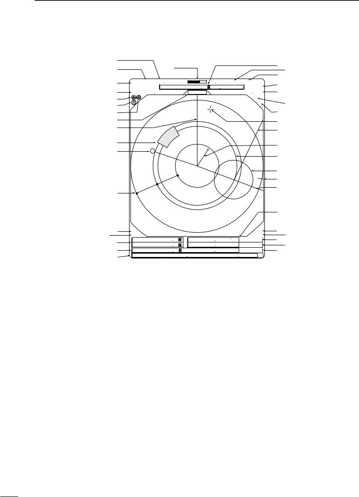
2 PANEL DESCRIPTION
■ Screen
@2 |
|
|
|
|
|
|
#9$0 |
@3 |
|
@1 |
|
|
|
|
|
@4 |
|
M.TUNE |
|
|
|
: |
$1 |
(0.25) |
MTUNE |
|
TVECT |
6M |
$2 |
||
|
|
TRAILS |
|
||||
|
3/4 NM CURS |
0174˚R 0649NM 005 |
$3 |
||||
@5 |
STW157KT |
H UP |
HDG2530˚T |
||||
@6 |
|
|
|
|
|
IR |
$4 |
@7 |
|
|
|
|
|
ES |
|
|
|
|
|
|
|
|
|
@8 |
|
|
|
|
|
|
$5 |
@9 |
|
|
|
|
|
|
$6 |
#0 |
|
|
|
|
|
|
$7 |
|
|
|
|
|
|
|
|
#1 |
|
|
|
|
|
|
$8 |
|
|
|
|
|
|
|
|
#2 |
|
|
|
|
|
|
$9 |
|
|
|
|
|
|
|
|
|
|
|
|
|
|
|
%0 |
|
|
|
|
|
|
|
%1 |
|
|
|
|
|
|
|
%2 |
#3 |
|
|
|
|
|
|
|
|
|
|
|
|
|
|
%3 |
#5#4 |
GPS |
|
|
|
|
ALM |
%4 |
COMPASS |
1076˚R |
|
|
|
ZOOM |
%5 |
|
#6 |
EBL1 |
VRM1 0422NM |
|
001: |
%6 |
||
EBL2 |
0219˚R |
VRM2 0242NM |
|
: |
%7 |
||
|
|
000 |
|||||
#7 |
WPT |
2834˚R |
|
0632NM |
|
: |
%8 |
|
|
001 |
|||||
#8 |
CURS |
34˚ 39720N 135˚ 34420E |
|
||||
|
|
|
|
|
|
|
|
@1TUNING LEVEL INDICATOR (p. 9)
Shows the receiver tuning level.
@2TUNING MODE INDICATOR (p. 9)
“M.TUNE” appears when the manual tuning function is in use.
@3FIXED RING RANGE READOUT (p. 14) Shows the interval range of the fixed ring.
•This readout appears when the “RING” of the FUNCTION menu is turned ON.
@4SCREEN RANGE READOUT (p. 14)
Shows the maximum range of the displayed screen.
• The range indicated is nautical miles (NM).
@5SHIP SPEED READOUT (p. 13)
Shows the ship speed.
•SOG: When GPS is selected in the INT. SETTING menu.
•STW: When LOG is selected in the INT. SETTING menu.
@6AUTO SEA INDICATOR (p. 10)
Appears when the automatic SEA control function is turned ON.
@7LONG PULSE INDICATOR (p. 13) Appears when the long pulse is in use.
@8RAIN CONTROL INDICATOR (p. 10) Appears when the RAIN function is in use.
@9MODE INDICATOR
Head-up, Course-up, North-up and True Motion screens are available.
•N UP and C UP screens require external bearing data. (p. 39)
•TM screen requires bearing data and LOG or position data.
#0HEADING LINE (p. 9)
Heading line indicates the ships bow.
#1ALARM ZONE (p. 17) Shows the alarm zone.
•Appears when the alarm function is in use.
#2WAYPOINT MARKER (p. 13)
Shows the waypoint received from navigation equipment.
•This marker appears when the “WPT” of the FUNCTION menu is turned ON.
•To display the waypoint marker, bearing data and NMEA data with 0183 format is necessary. (p. 39)
#3FIXED RANGE RINGS (p. 14)
Shows the distance in fixed intervals. The interval distance is indicated by the ring range readout (@3).
•These rings appear when the “RING” of the FUNCTION is turned ON.
#4GPS indicator (p. 24)
Indicator appears when the GPS or DGPS receiver is connected.
4

#5COMPASS INDICATOR (pgs. 24, 39)
• GYRO |
: NMEA (gyro) is connected. |
• COMPASS |
: NMEA (compass), N+1 or AUX data is |
|
connected. |
#6EBL1/ 2 READOUTS (pgs. 15–16)
Shows the bearing of the displayed Electronic Bearing Lines (EBL1 and EBL2) when the EBL is in use.
• EBL2 shows PI (!0) readout.
#7WAYPOINT/MOB READOUTS (p. 13)
Shows the bearing and distance to the waypoint received from navigation equipment.
•This readout appears when the “WPT” of the FUNCTION menu is turned ON.
•To display the waypoint/MOB marker, bearing data
and NMEA data with 0183 format is necessary. (p. 39)
Shows the bearing and distance to the MOB (Man Over Board) event marker.
•Push [MOB]/[  ] to cancel the readout and the symbol.
#8POSITION/CURSOR READOUT (p. 13)
Shows your own ship or cursor latitude and longitude readout when external NMEA data with 0183 format is connected.
•Select ‘SHIP’ or ‘CURS’ in the “POSN DISP” of the FUNCTION menu.
•To display the POSITION; NMEA 0183 is necessary.
•To display the CURSOR; NMEA 0183 and bearing data are necessary.
#9CURSOR INDICATOR
Shows the bearing and distance to the cursor.
$0VECTOR INDICATOR (p. 18)
Shows the ATA and OWN vector type.
•T: True vector
•R: Relative vector
$1VECTOR TIME INDICATOR (p. 18)
Shows the vector interval time. Select vector time in the “TRAIL TIME” of the VIDEO menu.
•30 min. is applied, when ‘∞’ is selected for the vector time.
$2TRAILS INDICATOR (p. 12)
Shows the trail time.
•Echo remains with gradation during the trail time period on the screen. (Except for the trail time; ∞)
•Progressing time counter starts to count the time until the timer reaches the trail time.
$3HEADING INDICATOR
Shows the heading bearing readout.
•The HDG readout indicates the bow of the ship’s bearing in a clockwise direction from north.
PANEL DESCRIPTION 2
$4IR INDICATOR (p. 11)
Eliminates or reduces interference caused by other radar operating nearby.
•This function is available when the “IR” in the VIDEO menu is set to 1 or 2.
$5ECHO STRETCH INDICATOR (p. 6)
Appears when the echo stretch function is in use.
•This function is available when the “STRETCH” of the VIDEO menu is turned ON.
$6CROSS LINE CURSOR
Used for measuring the bearing and distance, setting the alarm zone, selecting the ATA targets, etc.
• Push [Ù Ú Ω ≈] several times to move the cursor.
$7EBL2 (pgs. 15–16)
Used for bearing measurement. When a target is selected, the EBL readout (#6) shows the bearing.
$8OWN SHIP VECTOR INDICATOR
Shows the vector of your own ship.
$9VRM 1 (pgs. 15–16) %0VRM 2 (pgs. 15–16)
Used for distance measurement. When a target is selected, the VRM1/2 readout (%3) shows the distance.
%1NORTH MARK
The north mark shows the true north direction.
%2EBL1 (pgs. 15–16)
Used for bearing measurement. When a target is selected, the EBL readout (#6) shows the bearing.
%3VRM1/2 READOUTS (pgs. 15–16)
Shows the distance of the displayed Variable Range Markers (VRM1 and VRM2) when the VRM is in use.
•Nautical miles (NM) and kilometers (KM) can be selected in the FUNCTION menu as the distance unit.
%4ALARM INDICATOR (p. 17)
Appears when the alarm function is in use.
%5ZOOM INDICATOR (p. 11)
Appears when the zoom function is in use.
•Push [TARGET]/[  ] and [TRAILS]/[
 ] simultaneously to turn the function ON or OFF.
%6TIME INDICATOR
%7TIME INDICATOR
Shows the estimated time to the marker edge from center of the marker with current speed.
%8TIME INDICATOR
Shows the estimated time to the waypoint with current speed.
5

3 MENU
■ VIDEO |
|
|
|
|
|
|
|
|
|
|
■ FUNCTION |
|
|
|
|
||||
|
VIDEO MENU |
|
|
|
|
|
|
|
|
|
|
|
FUNCTIONMENU |
|
|
|
|||
|
|
|
|
|
|
|
MANUAL |
|
|
|
|
OFF |
|
|
|
||||
TUNE |
|
AUTO |
|
|
|
RING |
|
|
ON |
|
|||||||||
|
|
|
|
|
|
|
|
|
|
|
|
|
WPT |
|
|
ON |
|
||
|
|
|
|
|
|
|
|
|
|
|
|
|
OFF |
|
|
||||
D.RANGE |
|
|
|
|
|
|
MID. |
WIDE |
|
|
|||||||||
|
|
|
|
|
|
|
|
|
CURS |
|
|||||||||
|
NAR. |
|
|
|
POSN DISP |
SHIP |
|
|
|||||||||||
IR |
|
OFF |
|
|
|
1 |
|
|
|
|
|
|
|
|
|||||
|
|
|
2 |
DIST UNIT |
NM |
|
KM |
|
|||||||||||
STRETCH |
|
|
|
|
|
|
ON |
|
|
|
|
|
|
||||||
|
OFF |
|
|
|
|
BRG |
TRUE |
|
MAG |
|
|||||||||
PULSE |
|
|
|
|
|
|
LP |
|
|
|
|
|
|
||||||
|
SP |
|
|
|
|
EBL/PI |
TRUE |
|
360˚R |
PT/SB |
|||||||||
|
|
|
|
|
|
|
|
||||||||||||
|
|
|
|
|
|
||||||||||||||
SEA |
1 |
2 |
3 |
4 |
|
|
|
ZONE ALARM |
IN |
|
OUT |
|
|||||||
TRAIL TIME |
|
6S |
15S |
30S |
1M |
BEEP |
OFF |
|
|
|
|||||||||
|
ON |
|
|||||||||||||||||
|
|
|
|
3M |
6M |
|
15M |
|
|
|
|
|
|
|
|
||||
DTUNE
• AUTO : Automatic tuning.
•“A.TUNE” appears for approx. 2 sec. instead of the screen display, when first transmitting after turning the power ON. The unit also retunes in some cases.
•MANUAL : Manual tuning.
Push [≈] to select [MANUAL] then push [Ú] to activate the manual tuning slider. Push [Ω ≈] to adjust desired tuning level.
DPULSE |
|
• SP |
: Select the short pulse. |
• LP |
: Select the long pulse. LP indicator ap- |
|
pears on the screen. |
DSEA
•The characteristic (curve) of a SEA knob can be chosen as the optimal characteristic out of four kinds with the height of an antenna.
DTRAIL TIME
• 6S,15S, 30S, 1M, 3M, 6M, 15M or ∞ :
Select the plot interval and vector time.
DRING |
|
• OFF |
: Turn the fixed range ring display OFF. |
• ON |
: Turn the fixed range ring display ON. |
DWPT |
|
• OFF |
: Non display the way point on the screen. |
• ON |
: Display the way point on the screen. |
DPOSN DISP |
|
• SHIP: |
: Display your own ship’s position.* |
• CURS |
: Display the cursor position.** |
*External latitude/longitude data required.
**External latitude/longitude data and bearing data required.
DDIST UNIT
• NM |
: Display the distance unit in Nautical Mile. |
• KM |
: Display the distance unit in Kilometer. |
DBRG
Select the displayed bearing type, no relation with the bearing data format (NMEA, N+1 or AUX).
• TRUE |
: Select the true bearing. |
• MAG |
: Select the magnetic bearing. |
DEBL/PI (except HDG and CSE) (p. 15) |
|
• TRUE |
: True or magnetic direction. |
•360°R : Relative direction
•PT/SB : Bow direction
DZONE ALARM
• IN |
: Alarm is emitted when the target comes into |
|
the zone. |
• OUT |
: Alarm is emitted when the target goes out |
|
of the zone. |
DBEEP |
|
• OFF |
: Turn the beep tone OFF*. |
• ON |
: Turn the beep tone ON. |
* Except alarm function.
6
■ ATA (Automatic Tracking Aid)
|
A T A MENU |
|
|
|
||
|
|
|
|
|
ON |
|
|
|
OFF |
|
|||
A T A |
|
|
|
|
||
No.DISP |
|
|
OFF |
|
|
ALL |
|
|
|
SEL |
|||
VECT |
|
|
|
|
REL |
|
|
|
TRUE |
|
|||
OWN VECT |
|
|
|
|
ON |
|
|
|
OFF |
|
|||
ALARM |
|
|
|
|
ON |
|
|
|
OFF |
|
|||
CPA LIMIT |
|
|
1.0NM |
|
|
|
TCPA LIMIT |
|
|
1 MIN |
|
|
|
DATA |
|
• OFF |
: Turn the ATA function OFF. |
• ON |
: Turn the ATA function ON. |
DNo.DISP |
|
• OFF |
: Non display any mark number. |
• Sel |
: Display the selected mark number |
|
only. |
• ALL |
: Display all mark numbers. |
DVECT |
|
• TRUE |
: Select the true vector mode. |
• REL |
: Select the relative vector mode. |
DOWN VECT |
|
• OFF |
: Non display the own ship vector. |
• ON |
: Display your own ship’s vector. |
DALARM (CPA/TCPA) |
|
• OFF |
: Turn the alarm function OFF. |
• ON |
: Turn the alarm function ON. |
DCPA* LIMIT
• 0.1 to 10.0NM : Set the CPA (Closest Point of Approach) limit with [Ω ≈].
DTCPA* LIMIT
• 1 to 60MIN : Set the TCPA (Time to CPA) limit time with [Ω ≈].
*CPA/TCPA: Closest Point of Approach and Time to Closest Point of Approach limit is defined by the observer to given warning when a target or targets are close to within those limits from your own ship.
MENU 3
■ INT. SETTING
|
INT. SETTING |
|
|
|
|
||||||||
|
|
|
|
|
|
MANUAL |
|
||||||
|
|
AUTO |
|
||||||||||
MAG VAR |
|
|
|
||||||||||
|
|
|
|
|
|
|
|
|
|
7.2˚ W |
|
||
BRG INPUT |
|
NMEA |
|
|
N+1 |
AUX |
GPS |
||||||
SPD INPUT |
|
|
|
|
|
|
|
|
|
LOG |
|
||
|
|
GPS |
|
|
|
|
|
||||||
TX INH START |
|
|
|
|
0˚ |
|
|
|
|
|
|
|
|
TX INH ANGLE |
|
|
|
|
0˚ |
|
|
|
|
|
|
30M |
|
SAVE TIME |
|
|
1M |
|
|
|
6M |
|
15M |
||||
SYMBOL |
|
|
|
2 |
3 |
|
|
|
|
||||
1 |
|
|
|
|
|
||||||||
CHARACTER |
1 |
|
|
|
|
3 |
|
|
|
BRILL |
|||
2 |
|
|
|
|
|||||||||
KEY ILLUM |
1 |
|
2 |
3 |
|
4 |
|
|
|||||
DMAG VAR
• AUTO : Revise magnetic variation automatically.
NOTE: NMEA data is required. NEVER select “AUTO” without NMEA data, incorrect variation data may entered. (p. 39)
•MANUAL : Revise magnetic variation manually.
•Push [≈] to select [MANUAL], then push [Ú]. Set the revise value with [Ω ≈]. Push [Ú] or [MENU] to abort the menu.
DBRG INPUT
• NMEA |
: NMEA0183 bearing data format. |
• N+1 |
: N+1 data format. |
• AUX |
: Other format. |
• GPS |
: Reads NMEA0183 COG format data as |
|
HDG format. |
DSPD INPUT |
|
• GPS |
: Use the GPS NMEA speed data. |
• LOG |
: Use the speed sensor data. |
DTX INH START
• 0 to 359° : Push [Ω ≈] to enter the start point of the TX inhibit area.
DTX INH ANGLE
• 0 to 90° : Push [Ω ≈] to enter the TX inhibit area.
DSAVE TIME
•1M, 6M, 15M or 30M
:Select the stand by time during save mode.
* The radar for TX interval scan is fixed at 10 revolutions.
DSYMBOL |
|
• 1/2/3 |
: Select the symbol brightness. |
DCHARACTER |
|
• 1/2/3 |
: Select the character brightness. |
DKEY ILLUM |
|
• 1/2/3/4 |
: Select the key illumination brightness. |
7
4 BASIC OPERATION
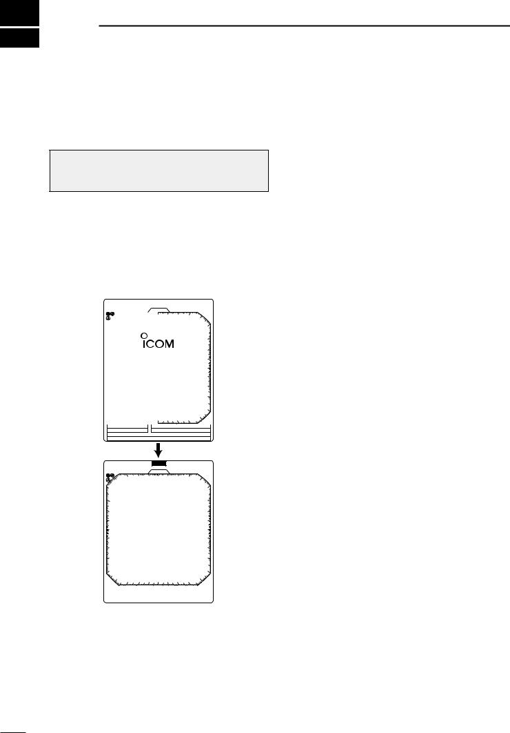
■ Checking the installation
Before turning the power ON, be sure all the connections are complete. The checklist at right may be helpful for necessary confirmation.
CAUTION: Connect the scanner unit before turning the power ON. Otherwise the magnetron inside the scanner unit might be damaged.
DChecklist
qThe 4 bolts securing the scanner unit must be firmly tightened.
wCabling must be securely attached to a mast or mounting material, and must not interfere with the rigging.
eBe sure waterproofing procedures are completed on the system cable.
rThe power connections to the battery must be of the correct polarity.
tBe sure that the plugs at the rear of the display unit have been connected correctly and securely.
(See p. 24 for details.)
■ Turning power ON/OFF
1 |
(0.25) |
|
T.VECT 6M |
NM CURS |
000 . 0 ˚ T |
0.000NM |
|
SOG17 . 7KT |
H UP |
HDG253 . 4 ˚ T |
|
|
|
|
IR |
|
|
0.45 |
|
|
|
|
R E V |
*.* |
|
|
|
ROM |
OK |
|
|
|
RAM |
OK |
|
GPS |
|
|
|
|
COMPASS |
|
|
|
|
E B L 1 |
|
V R M 1 |
|
|
E B L 2 |
|
V R M 2 |
|
|
MOB |
|
|
|
|
CURS |
3 4 ˚ 3 7 . 7 2 N |
1 3 5 ˚ 3 4 .4 2 E |
||
(0.25) |
|
S TB Y |
T.VECT 6M |
|
1 NM |
CURS |
000 . 0 ˚ T |
0.000NM |
|
SOG17 . 7KT |
H UP |
HDG253 . 4 ˚ T |
||
|
|
|
|
IR |
GPS
COMPASS
E B L 1 |
|
|
V R M 1 |
|
E B L 2 |
|
|
V R M 2 |
|
MOB |
|
|
|
|
CURS |
3 4 ˚ 3 7 . 7 2 N 1 3 5 ˚ 3 4 .4 2 E |
|||
qPush [POWER]/[ 
 ] to turn the power ON.
•The initial screen appears and warming up time is counted down on the screen.
•The magnetron inside the scanner unit warms up for 90 sec.
•[POWER]/[ 
 ] does not function for 2 sec. after the power is turned OFF.
wWhen the countdown is completed, the Standby screen appears.
ePush [TX]/[

 ] to start scanning and select the Plan Position Indicator (PPI) screen.
•Targets and heading marker appear.
•The screen appears approx. 2 sec. after turning the power on, when ‘AUTO’ is selected in the “TUNE” of the VIDEO menu.
r Push [POWER]/[ 
 ] to turn the power OFF.
8
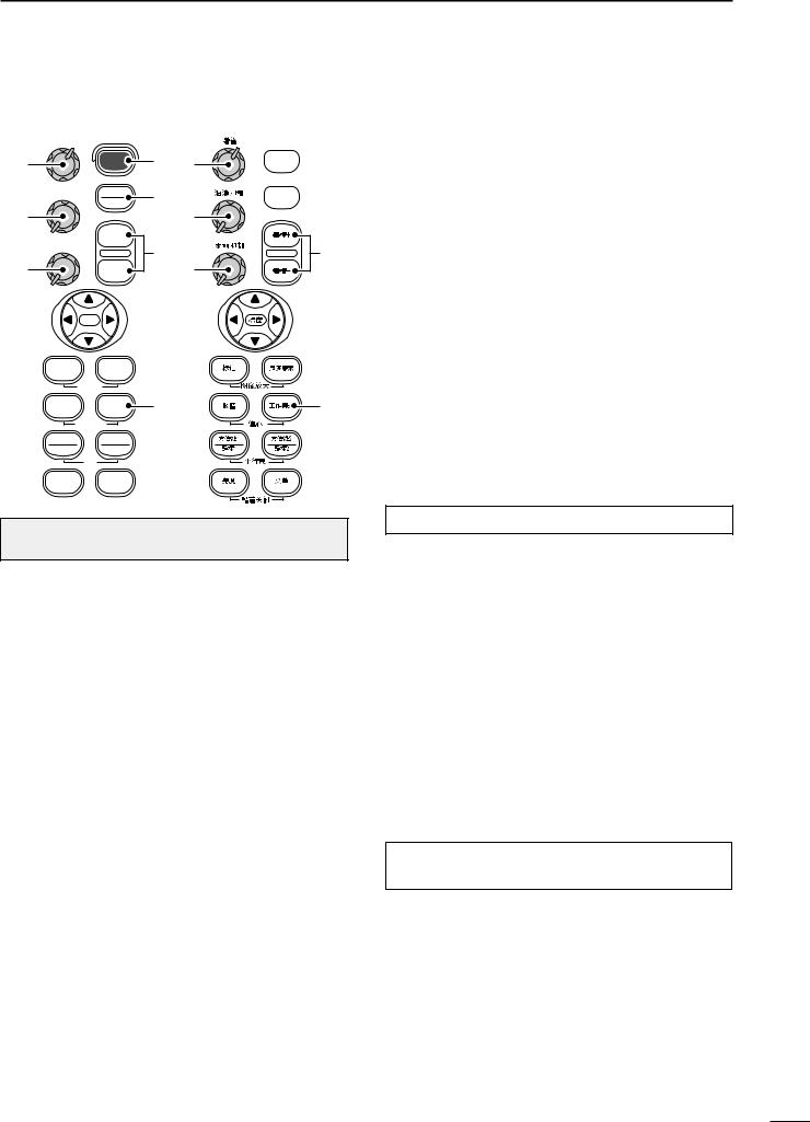
■ Basic operation
r
t
y
GAIN |
SEA |
RAIN |
POWER |
q |
r |
|
|
|
TX |
w |
|
SAVE |
|
|
|
|
|
+ |
|
t |
e |
|
|
- |
|
|
|
y |
 q
q  w
w
e |
|
MOB |
|
|
TARGET |
TRAILS |
|
|
|
ZOOM |
|
|
ALM |
MODE |
u |
u |
OFF CENT |
|
|
|
EBL1 |
EBL2 |
|
|
VRM1 |
VRM2 |
|
|
PI
BRILL MENU
 HL OFF
CAUTION: When setting the [SEA]/[
 ] control to a fully clockwise position, close targets are blanked.
DHeading marker
The heading marker is a line that shows your ship’s bow direction. (This marker will appear in the center of the screen when the Head-up screen H UP is selected.) The heading marker can be hidden when the desired target is located under the heading marker.
•Push and hold [BRILL]/[ ] and [MENU]/[
 ] simultaneously to hide the heading marker.
DFixed range rings
The fixed range rings can be used for rough distance measurement. (p. 14)
Push [MENU]/[ ] to open the FUNCTION menu, then push [Ú] to select RING. Push [≈] to turn the ring ON.
BASIC OPERATION 4
q Turn the power ON.
w Push [TX]/[

 ] after the countdown disappears from the screen.
• See “Turning power ON/OFF” on page at left.
ePush [+]/[
 ] or [–]/[
 ] several times to select the display range.
•The screen range readout shows the maximum range of the screen.
rTurn [GAIN]/[ ] to set 1 o’clock position.
•Clockwise rotation increases the gain.
•Increased gain may increase screen noise.
tTurn [SEA]/[
 ] to set the sensitivity time control for minimum.
yTurn [RAIN]/[
 ] to set the rain clutter control for minimum.
uPush [MODE]/[ 
 ] to select one of Head-up;H UP, Course-up;C UP, North-up;N UP or True Motion;TM screens.
C UP, N UP or TM can be selected only when bearing, position or speed data are connected.
(See p. 39 for details)
NOTE: Manual adjustment can be used. (See below.)
DManual tuning
The receiver tuning can be manually adjusted. Push [MENU]/[ ] to open the VIDEO menu, then
select MANUAL. Push [Ú] to activate the manual tuning slider, then push [Ω ≈] to set the tuning level indicator to the maximum level. (p. 6)
• “M.TUNE” appears on the top of the display.
DBrilliance adjustment
The intensity of the screen can be adjusted. When you require continuous operation, but not constant viewing, a lower setting can increase the life of the CRT display.
NOTE: High intensity will shorten the life of the CRT display.
• Key illumination
The backlighting of the keys can be adjusted for convenient operation. (p. 7)
Push [MENU]/[ ] four times to call up the INT. SETTING menu. Push [Ω ≈] to select the illumination level.
• Key illumination corresponds with [BRILL]/[ ] control.
9
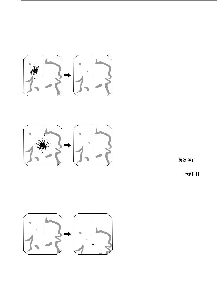
4 BASIC OPERATION
The following are typical basic operation examples, which may hinder radar reception (sea clutter, precipitation interference and echoes from other radar).
■ RAIN function
This function eliminates reflection echoes from rain, snow, fog etc.
• Rotate the control fully counterclockwise to deactivate the control function. The RAIN indicator ( ) disappears.
• NOTE: DO NOT reduce the reflection echoes too much, otherwise you may miss weaker targets.
Small echos Adjust RAIN control
■ SEA function
This function serves to eliminate echoes from waves at close range. Reduce the receiver gain for close objects within a radius of 8 miles to eliminate sea clutter.
• Rotate the control fully clockwise to activate the automatic control function. SEA indicator ( )appears in the upper left
|
|
|
of the screen. |
|
|
|
|
|
|
|
|
|
|
|
|
|
|
WARNING: The [SEA]/[ |
] control re- |
|
|
|
duces the receiver sensitivity of objects within 8 |
|
Echos from |
sea waves |
Adjust SEA control |
miles. Therefore, caution and careful adjustment are |
|
|
|
|
necessary when using the [SEA]/[ |
] control. |
|
|
|
Small objects may not be displayed on the screen |
|
|
|
|
when strong echoes from the rain or the island within |
|
|
|
|
1 NM while automatic SEA function is activating. |
|
|
|
|
|
|
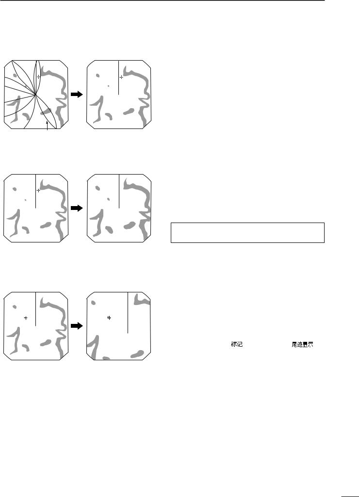
■ OFF CENTER function
The scanning area can be shifted in a desired direction and can be enlarged partially. This is useful when the Head-up* is selected and you want to enlarge the bow direction display, or, the center of the screen shifts in the direction of the intersection.
|
|
• This function is available for 24NM or shorter range selec- |
|
|
tion. |
|
|
*This function is not available in the TM screen. |
|
|
q Push [Ù Ú Ω ≈] to move the cursor where you |
Normal screen |
With OFF CENTER ON |
want to shift the center of the screen. |
|
|
• Max. offsetting is up to 75% of the screen. |
w Push [ALM]/[ ] and [MODE]/[
 ] simultaneously to shift the screen.
e Push [ALM]/[ ] and [MODE]/[
 ] simultaneously again to return to the normal screen.
10
BASIC OPERATION 4
■ IR function
Radar interference may appear when another ship’s radar is operating on the same frequency band in close proximity. The IR function can eliminate this type of interference. (p. 6)
q Push [MENU]/[ ] to call up VIDEO menu.
w Push [Ú] until the “IR” section becomes highlighted. e Push [Ω ≈] to select IR function 1, 2 or OFF.
• “IR” appears in the upper right of the screen, when the function is activated.
Radar interference |
With IR function ON |
■ STRETCH function
The blips can be magnified electronically for easier viewing of small targets. (p. 6)
q Push [MENU]/[ ] to open the VIDEO menu.
w Push [Ú] to select “STRETCH”, then push [≈] to turn the function ON.
NOTE: Turn OFF this function during normal operation.
Normal screen |
With STRETCH ON |
■ ZOOM function
The ZOOM function expands the target to two times normal size.
• This function is available up to a 24 NM range or shorter except 1⁄8 NM.
|
|
q Push [Ù Ú Ω ≈] to move the cursor to the desired |
|
|
|
target. |
|
|
|
w Push [TARGET]/[ ] and [TRAILS]/[ |
] si- |
|
|
multaneously to toggle the ZOOM function ON and |
|
|
|
OFF. |
|
Normal screen |
With ZOOM function ON |
• “ZOOM” appears in the lower right of the screen. |
|
11
 Loading...