


IC-M32
INSTRUCTION MANUAL
VHF MARINE TRANSCEIVER
iM32
This device complies with Part 15 of
the FCC Rules. Operation is subject
to the condition that this device does
not cause harmful interference.

SAFETY TRAINING INFORMATION
CAUTION
WARNING
Your Icom radio generates RF electromagnetic energy during
transmit mode. This radio is designed for and classified as
“Occupational Use Only”, meaning it must be used only during
the course of employment by individuals aware of the hazards, and the ways to minimize such hazards. This radio is
NOT intended for use by the “General Population” in an uncontrolled environment.
This radio has been tested and complies with the FCC RF exposure limits for
“Occupational Use Only”. In addition, your Icom radio complies with the following Standards and Guidelines with regard to RF energy and electromagnetic
energy levels and evaluation of such levels for exposure to humans:
• FCC OET Bulletin 65 Edition 97-01 Supplement C, Evaluating Compliance
with FCC Guidelines for Human Exposure to Radio Frequency Electromagnetic Fields.
• American National Standards Institute (C95.1-1992), IEEE Standard for
Safety Levels with Respect to Human Exposure to Radio Frequency Electromagnetic Fields, 3 kHz to 300 GHz.
• American National Standards Institute (C95.3-1992), IEEE Recommended
Practice for the Measurement of Potentially Hazardous Electromagnetic
Fields– RF and Microwave.
• The following accessories are authorized for use with this product. Use of
accessories other than those specified may result in RF exposure levels
exceeding the FCC requirements for wireless RF exposure.; Belt Clip (MB68/74/74N/87), Rechargeable Ni-Cd Battery Pack (BP-224) and Alkaline
Battery Case (BP-223).
To ensure that your expose to RF electromagnetic energy is within the FCC allowable limits for occupational
use, always adhere to the following guidelines:
• DO NOT operate the radio without a proper antenna attached, as this may
damaged the radio and may also cause you to exceed FCC RF exposure
limits. A proper antenna is the antenna supplied with this radio by the manufacturer or antenna specifically authorized by the manufacturer for use
with this radio.
• DO NOT transmit for more than 50% of total radio use time (“50% duty
cycle”). Transmitting more than 50% of the time can cause FCC RF exposure compliance requirements to be exceeded. The radio is transmitting
when the “TX indicator” lights red. You can cause the radio to transmit by
pressing the “PTT” switch.
• ALWAYS keep the antenna at least 2.5 cm (1 inch) away from the body
when transmitting and only use the Icom belt-clips which are listed on
page 32 when attaching the radio to your belt, etc., to ensure FCC RF exposure compliance requirements are not exceeded. To provide the recipients of your transmission the best sound quality, hold the antenna at least
5 cm (2 inches) from your mouth, and slightly off to one side.
The information listed above provides the user with the information needed to
make him or her aware of RF exposure, and what to do to assure that this radio
operates with the FCC RF exposure limits of this radio.
Electromagnetic Interference/Compatibility
During transmissions, your Icom radio generates RF energy that can possibly
cause interference with other devices or systems. To avoid such interference,
turn off the radio in areas where signs are posted to do so. DO NOT operate
the transmitter in areas that are sensitive to electromagnetic radiation such as
hospitals, aircraft, and blasting sites.
Occupational/Controlled Use
The radio transmitter is used in situations in which persons are exposed as
consequence of their employment provided those persons are fully aware of
the potential for exposure and can exercise control over their exposure.
i
IN CASE OF EMERGENCY
RECOMMENDATION
If your vessel requires assistance, contact other vessels and
the Coast Guard by sending a distress call on Channel 16.
❍ USING CHANNEL 16
DISTRESS CALL PROCEDURE
1. “MAYDAY MAYDAY MAYDAY.”
2. “THIS IS ...........................” (name of vessel)
3. Your call sign or other indication of the vessel.
4. “LOCATED AT .....................” (your position)
5. The nature of the distress and assistance required.
6. Any other information which might facilitate
the rescue.
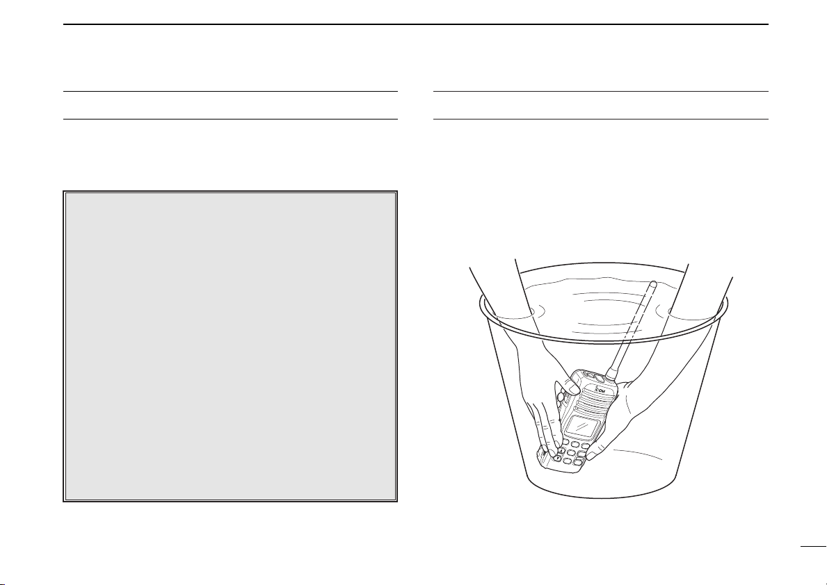
CLEAN THE TRANSCEIVER THOROUGHLY WITH FRESH
WATER after exposure to saltwater, and dry it before opera-
tion. Otherwise, the transceiver’s keys, switches and controllers may become inoperable due to salt crystallization.
ii

FOREWORD
WORD
DEFINITION
RWARNING
CAUTION
NOTE
Personal injury, fire hazard or electric shock
may occur.
If disregarded, inconvenience only. No risk
of personal injury, fire or electric shock.
Equipment damage may occur.
FEATURES
Thank you for purchasing this Icom product. The IC-M32 VHF
MARINE TRANSCEIVER is designed and built with Icom’s state
of the art technology and craftsmanship. With proper care this
product should provide you with years of trouble-free operation.
IMPORTANT
READ ALL INSTRUCTIONS carefully and com-
pletely before using the transceiver.
SAVE THIS INSTRUCTION MANUAL—This in-
struction manual contains important operating instructions for
the IC-M32.
EXPLICIT DEFINITIONS
iii
☞ Waterproof construction
Built tough to withstand the punishing marine environment, the IC-M32 meets JIS waterproof specification
grade 7 while using BP-223 (option) or BP-224.
☞ Dualwatch and tri-watch functions
Convenient functions which allow you to monitor the distress channel (Ch 16) while receiving a channel of your
choice—dual watch; or monitor the distress channel and
another channel while receiving a channel of your
choice—tri-watch.
☞ Large, easy-to-read LCD
With dimensions of 16(H) × 32(W) mm;
the IC-M32’s function display is easy to read and shows operating conditions at a glance. Backlighting and contrast
can be adjusted to suit your preferences.
5
⁄8(H) × 11⁄4(W) inch,
☞ Simple operation
9 large buttons on the front panel provide user-friendly operation. The independent volume and channel buttons are
located on the front panel for convenient one-hand operation.

PRECAUTION
RWARNING! NEVER connect the transceiver to an
AC outlet. This may pose a fire hazard or result in an electric
shock.
RWARNING! NEVER hold the transceiver so that the
antenna is very close to, or touching exposed parts of the
body, especially the face or eyes, while transmitting. The
transceiver will perform best if the microphone is 5 to 10 cm
(2 to 4 inches) away from the lips and the transceiver is vertical.
NEVER connect the transceiver to a power source other
than the BP-223 or BP-224. Such a connection will ruin the
transceiver.
AVOID using or placing the transceiver in direct sunlight or
in areas with temperatures below –20°C (–4°F) or above
+60°C (+140°F).
KEEP the transceiver out of the reach of children.
KEEP the transceiver at least 0.9 meters (3.0 ft) away from
your vessel’s magnetic navigation compass.
BE CAREFUL! The transceiver’s right-side panel will
become hot when operating continuously for long periods.
BE CAREFUL! The IC-M32 employs waterproof con-
struction, which corresponds to JIS waterproof specification,
Grade 7 (1 m; 3 ft depth for 30 min.). However, once the
transceiver has been dropped, waterproofing cannot be guaranteed due to the fact that the transceiver may be cracked,
or the waterproof seal damaged, etc.
MAKE SURE the flexible antenna and battery pack are
securely attached to the transceiver, and that the antenna and
battery pack are dry before attachment. Exposing the inside
of the transceiver to water will result in serious damage to the
transceiver.
For U.S.A. only
CAUTION: Changes or modifications to this device, not
expressly approved by Icom Inc., could void your authority to
operate this device under FCC regulations.
Icom, Icom Inc. and the logo are registered trademarks of Icom Incorporated (Japan) in the United States, the United Kingdom, Germany, France,
Spain, Russia and/or other countries.
iv

TABLE OF CONTENTS
SAFETY TRAINING INFORMATION ................................... i
IN CASE OF EMERGENCY ............................................... ii
RECOMMENDATION .......................................................... ii
FOREWORD ...................................................................... iii
IMPORTANT ....................................................................... iii
EXPLICIT DEFINITIONS .................................................... iii
FEATURES ......................................................................... iii
PRECAUTION .................................................................... iv
TABLE OF CONTENTS ...................................................... v
1 OPERATING RULES ...................................................... 1
2 SUPPLIED ACCESSORIES AND ATTACHMENTS.... 2–3
■ Supplied accessories ................................................... 2
■ Attachments ................................................................. 2
3 PANEL DESCRIPTION ............................................... 4–7
■ Front, top and side panels ............................................ 4
■ Function display .......................................................... 6
4 BASIC OPERATION ................................................. 8–13
■ Channel selection ........................................................ 8
■ Adjusting the volume level ......................................... 10
■ Adjusting the squelch level ........................................ 10
■ Receiving and transmitting ........................................ 11
■ Call channel programming ........................................ 12
■ Lock function ............................................................. 13
■ Automatic backlighting .............................................. 13
■ Monitor function ......................................................... 13
5 SCAN OPERATION ................................................ 14–15
■ Scan types ................................................................. 14
■ Setting tag channels .................................................. 15
■ Starting a scan .......................................................... 15
6 DUALWATCH/TRI-WATCH .......................................... 16
■ Description ................................................................ 16
■ Operation ................................................................... 16
7 SET MODE ............................................................. 17–22
■ SET mode programming ........................................... 17
■ SET mode items ........................................................ 18
8 BATTERY CHARGING ........................................... 23–26
■ Battery charging ........................................................ 23
■ Battery caution .......................................................... 23
■ Optional battery case ................................................ 24
■ Optional battery chargers .......................................... 25
9 SWIVEL BELT CLIP ............................................... 27–28
■ MB-87 contents ......................................................... 27
■ To attach .................................................................... 27
■ To detach ................................................................... 28
10 TROUBLESHOOTING ................................................ 29
11 VHF MARINE CHANNEL LIST .................................... 30
12 SPECIFICATIONS ........................................................ 31
13 OPTIONS...................................................................... 32
v

OPERATING RULES
1
D Priorities
• Read all rules and regulations pertaining to priorities and
keep an up-to-date copy handy. Safety and distress calls
take priority over all others.
• You must monitor Channel 16 when you are not operating
on another channel.
• False or fraudulent distress calls are prohibited under law.
D Privacy
• Information overheard but not intended for you cannot lawfully be used in any way.
• Indecent or profane language is prohibited.
D Radio licenses
(1) SHIP STATION LICENSE
When your craft is equipped with a VHF FM transceiver, you
must have a current radio station license before using the
transceiver. It is unlawful to operate a ship station which is not
licensed.
Inquire through your dealer or the appropriate government
agency for a Ship-Radiotelephone license. This license includes the call sign which is your craft’s identification for radio
purposes.
(2) OPERATOR’S LICENSE
A restricted Radiotelephone Operator Permit is the license
most often held by small vessel radio operators when a radio
is not required for safety purposes.
The Restricted Radiotelephone Operator Permit must be
posted near the transceiver or be kept with the operator. Only
a licensed radio operator may operate a transceiver.
However, non-licensed individuals may talk over a transceiver
if a licensed operator starts, supervises, ends the call and
makes the necessary log entries.
A current copy of the applicable government rules and regulations is only required to be on hand for vessels in which a
radio telephone is compulsory. However, even if you are not
required to have these on hand it is your responsibility to be
thoroughly acquainted with all pertinent rules and regulations.
NOTE: Even though the IC-M32 is capable of operation
on VHF marine channels 3, 21, 23, 61, 64, 81, 82 and 83,
according to FCC regulations these simplex channels cannot be lawfully used by the general public in USA waters.
1
1
2
To attach the belt clip
To remove the belt clip
SUPPLIED ACCESSORIES AND ATTACHMENTS
■ Supplied accessories
The following accessories are supplied: Qty.
• Flexible antenna . . . . . . . . . . . . . . . . . . . . . . . . . . . . . . . . 1
• Handstrap . . . . . . . . . . . . . . . . . . . . . . . . . . . . . . . . . . . . . 1
• Belt clip (MB-68) . . . . . . . . . . . . . . . . . . . . . . . . . . . . . . . . 1
• Ni-Cd battery pack (BP-224) . . . . . . . . . . . . . . . . . . . . . . 1
• Battery charger (BC-150) . . . . . . . . . . . . . . . . . . . . . . . . . 1
• Screws for the BC-150 (M3.5 × 20) . . . . . . . . . . . . . . . . . 2
• AC adapter (BC-147A/E or BM-95V)* . . . . . . . . . . . . . . . . 1
* Depending on version
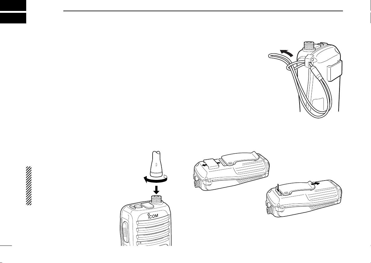
■ Attachments
D Flexible antenna
Connect the supplied flexible antenna to the antenna connector.
CAUTION!
• NEVER HOLD by the antenna
when carrying the transceiver.
• Transmitting without an an-
tenna may damage the transceiver.
D Handstrap
Pass the handstrap through
the loop on the side of the
transceiver as illustrated at
right. Facilitates carrying.
D Belt clip
Attach the belt clip to the transceiver as illustrated below.
2
ï Battery pack
OPEN
LO
C
K
Screw position
when removing battery
OPEN
L
O
C
K
Screw position
when attaching battery
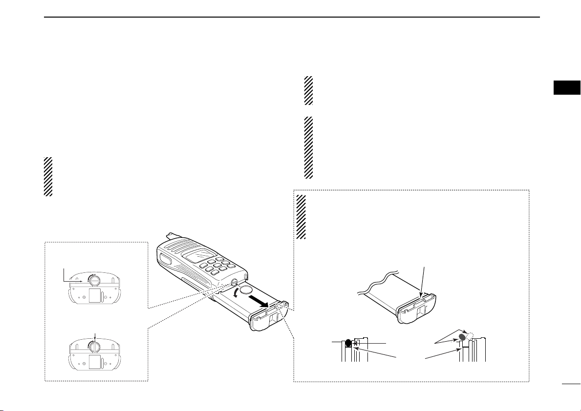
Make sure both the rubber seal (purple) is set to the groove
correctly and dust or else does not adhere to it.
Battery pack
Battery pack
Rubber seal
Groove
Correct position
Incorrect position
NOTE:
When attaching a battery pack, make sure dust or else does
not adhere to the rubber seal. If dust or else is on the seal
when attaching a battery pack, the water resistant may be
reduced.
To remove the battery pack:
Turn the screw counterclockwise, then pull the battery pack
in the direction of the arrow as shown below.
SUPPLIED ACCESSORIES AND ATTACHMENTS
NOTE: When removing or attaching the battery pack, use
a coin or flat-blade screwdriver to loosen or tighten the bottom screw.
2
2
To attach the battery pack:
Insert the battery pack in the IC-M32 completely, then turn the
screw clockwise.
NEVER remove or insert the battery pack when the transceiver is wet or soiled. This may result water or dust getting into the transceiver/battery pack and may result in the
transceiver being damaged.
CAUTION!:
When attaching or removing a battery pack, make sure the
rubber seal is set in the groove of the battery pack correctly. If the seal is not neatly in the groove it may be damaged when attaching the battery pack.
If the seal is damaged, waterproofing is not guaranteed.
3
r
q
o
u
i
!0
w
y
t
e
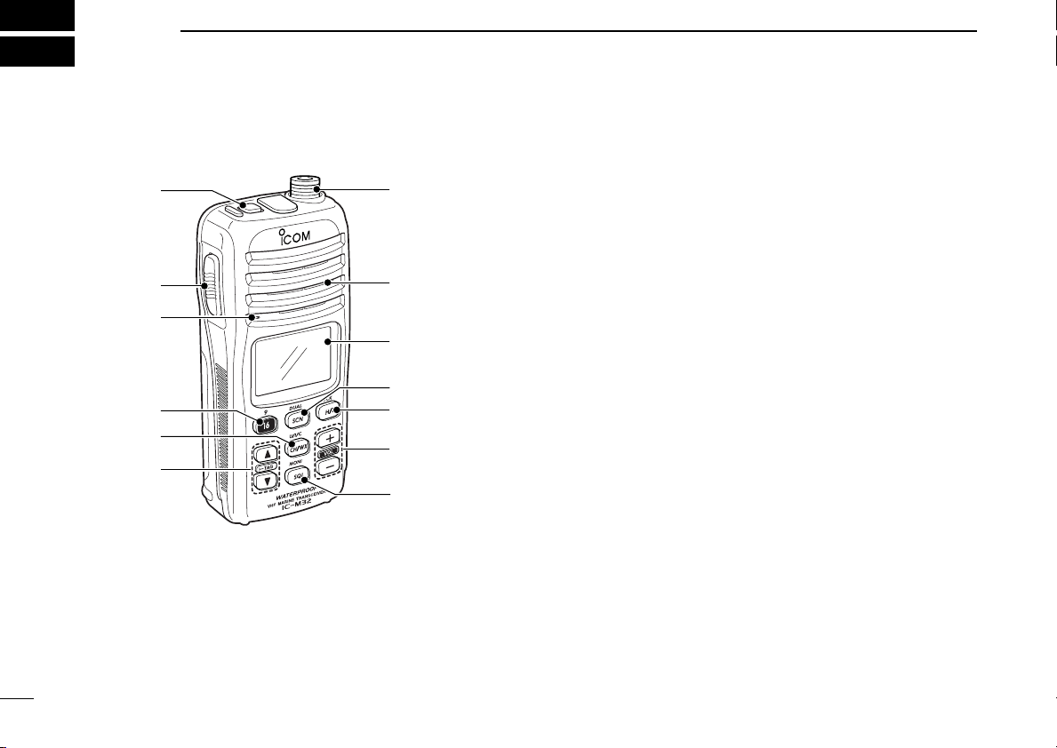
Microphone
Function display
(p. 6)
Speaker
4
3
PANEL DESCRIPTION
■ Front, top and side panels
q POWER SWITCH [PWR]
Push and hold to turn power ON and OFF.
w ANTENNA CONNECTOR (p. 2)
Connects the supplied antenna.
e SCAN/DUAL KEY [SCN•
• Starts and stops normal or priority scan. (p. 15)
• Enters watch mode when pushed for 1 sec. (p. 16)
• Exits watch mode when pushed during watch operation.
(p. 16)
r TRANSMIT POWER/LOCK KEY [H/L•
• Selects high or low power when pushed. (p. 11)
• Toggles the lock function ON/OFF when pushed for 1
sec. (p. 13)
t VOLUME UP/DOWN KEYS [+]/[–]•
• Adjusts the volume level. (p. 10)
• After pushing [SQL•
level. (p. 10)
y SQUELCH KEY [SQL•
• Push this key, then adjust the squelch level with [+]/[–].
(p. 10)
• Manually opens the squelch for monitoring the channel
while pushed and held. (p. 13)
• While pushing this key, turn power ON to enter the set
mode. (p. 17)
DUAL]
LOCK]
[VOL]
MONI], push to adjust the squelch
MONI]

PANEL DESCRIPTION
3
u CHANNEL UP/DOWN KEYS [YY]/[ZZ]•[TAG]
• Selects an operating channel. (pgs. 8, 9)
• Selects the SET mode condition of the item. (p. 17)
• Checks tag channels or changes scanning direction dur-
ing scan. (p. 15)
• Sets or clears the displayed channel as a tag (scanned)
channel when pushed both keys for 1 sec. (p. 15)
• While turning power ON, clears all tag channels in the selected channel group when both keys are pushed. (p. 15)
i CHANNEL/WEATHER CHANNEL KEY [CH/WX•
• Toggles the regular channels and weather channel when
pushed. (p. 9)
• Selects one of 3 (or 2*) regular channel groups in sequence when pushed for 1 sec. (p. 9)
- U.S.A., International and Canadian* channels are available.
*Canadian channels are available for the USA version only.
• Push to return to the channel selection before selecting
the channel 16 or the call channel with [16•9].
U/I/C]
o CHANNEL 16 KEY [16•9]
• Selects Channel 16 when pushed. (p. 8)
• Selects the call channel when pushed for 1 sec. (p. 8)
- Channel 9 is factory default.
• Enters call channel programming condition when the call
channel is selected and this key is pushed for 3 sec.
(p. 12)
• Exits set mode when pushed during set mode operation.
(p. 17)
!0 PTT SWITCH [PTT]
Push and hold to transmit; release to receive.
3
5
3 PANEL DESCRIPTION
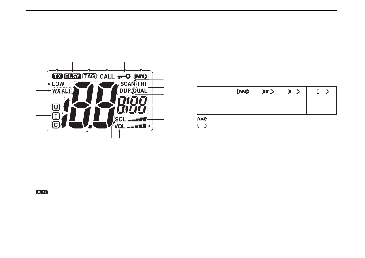
Indication
Full Middle
Charging
required
No battery
Battery level
blinks when the battery is exhaustion.
blinks when the battery over charged.
qe
ryt
w
!5 !3!4
i
u
o
!2
!1
!0
!8
!6
!7
■ Function display
q TRANSMIT INDICATOR (p. 11)
Appears while transmitting.
w BUSY INDICATOR
Appears when receiving a signal or when the squelch
opens. (p. 11)
6
“” blinks while monitoring. (p. 13)
e TAG CHANNEL INDICATOR (p. 15)
Appears when a tag channel is selected.
r CALL CHANNEL INDICATOR (p. 8)
Appears when the call channel is selected.
t LOCK INDICATOR (p. 13)
Appears while the lock function is activated.
y BATTERY INDICATOR
Indicates remaining battery power.
u SCAN INDICATOR (p. 15)
Blinks while scanning.
i DUALWATCH/TRI-WATCH INDICATORS (p. 16)
“DUAL” appears during dualwatch; “TRI” appears during
tri-watch.
o DUPLEX INDICATOR
Appears when a duplex channel is selected.
!0 SUB CHANNEL READOUT
• Indicates Channel 16 during priority scan, dualwatch or
tri-watch. (p. 16)
• Indicates the SET mode item while in SET mode. (p. 17)
• Indicates the squelch level while squelch setting. (p. 10)
• Indicates the volume level while volume setting. (p. 10)
 Loading...