


INSTRUCTION MANUAL
VHF AIR BAND TRANSCEIVER
iA24
iA6
This device complies with Part 15 of the FCC Rules. Operation is subject to the condition that this device does not cause harmful interference.
IC-A24 |
IC-A6 |

SAFETY TRAINING INFORMATION
Your Icom radio generates RF electromagnetic energy during transmit mode. This radio is designed for and classified as “Occupational Use Only”, meaning it must be used only during the course of employment by individuals aware of the hazards, and the ways to minimize such hazards. This radio is
W ARN ING NOT intended for use by the “General Population” in an uncontrolled environment.
This radio has been evaluated for compliance at the distance of 2.5 cm with the FCC RF exposure limits for “Occupational Use Only”. In addition, your Icom radio complies with the following Standards and Guidelines with regard to RF energy and electromagnetic energy levels and evaluation of such levels for exposure to humans:
•FCC OET Bulletin 65 Edition 97-01 Supplement C, Evaluating Compliance with FCC Guidelines for Human Exposure to Radio Frequency Electromagnetic Fields.
•American National Standards Institute (C95.1-1992), IEEE Standard for Safety Levels with Respect to Human Exposure to Radio Frequency Electromagnetic Fields, 3 kHz to 300 GHz.
•American National Standards Institute (C95.3-1992), IEEE Recommended Practice for the Measurement of Potentially Hazardous Electromagnetic Fields– RF and Microwave.
•The following accessories are authorized for use with this product. Use of accessories other than those specified may result in RF exposure levels exceeding the FCC requirements for wireless RF exposure.; Belt Clip (MB86/103), Rechargeable Ni-MH Battery Pack (BP-210N) and Alkaline Battery Case (BP-208N).
To ensure that your expose to RF electromagnetic energy is within the FCC allowable limits for occupational use, always adhere to the following guidelines:
CAU TIO N
•DO NOT operate the radio without a proper antenna attached, as this may damaged the radio and may also cause you to exceed FCC RF exposure limits. A proper antenna is the antenna supplied with this radio by the manufacturer or antenna specifically authorized by the manufacturer for use with this radio.
•DO NOT transmit for more than 50% of total radio use time (“50% duty cycle”). Transmitting more than 50% of the time can cause FCC RF exposure compliance requirements to be exceeded. The radio is transmitting when “ ” appears on the function display. You can cause the radio to transmit by pressing the “PTT” switch.
•ALWAYS keep the antenna at least 2.5 cm (1 inch) away from the body when transmitting and only use the Icom belt-clips which are listed on page 31 when attaching the radio to your belt, etc., to ensure FCC RF exposure compliance requirements are not exceeded. To provide the recipients of your transmission the best sound quality, hold the antenna at least 5 cm (2 inches) from your mouth, and slightly off to one side.
The information listed above provides the user with the information needed to make him or her aware of RF exposure, and what to do to assure that this radio operates with the FCC RF exposure limits of this radio.
Electromagnetic Interference/Compatibility
During transmissions, your Icom radio generates RF energy that can possibly cause interference with other devices or systems. To avoid such interference, turn off the radio in areas where signs are posted to do so. DO NOT operate the transmitter in areas that are sensitive to electromagnetic radiation such as hospitals and blasting sites.
Occupational/Controlled Use
The radio transmitter is used in situations in which persons are exposed as consequence of their employment provided those persons are fully aware of the potential for exposure and can exercise control over their exposure.
i
FOREWORD
Thank you for purchasing this Icom product. The IC-A24/A6 VHF AIR BAND TRANSCEIVER is designed and built with Icom’s state of the art technology and craftsmanship. With proper care this product should provide you with years of trouble-free operation.
IMPORTANT
READ ALL INSTRUCTIONS carefully and completely before using the transceiver.
SAVE THIS INSTRUCTION MANUAL— This in-
struction manual contains important operating instructions for
the IC-A24/A6.
EXPLICIT DEFINITIONS
WORD |
DEFINITION |
Personal injury, fire hazard or electric shock RWARNING may occur.
CAUTION Equipment damage may occur.
NOTE
If disregarded, inconvenience only. No risk of personal injury, fire or electric shock.
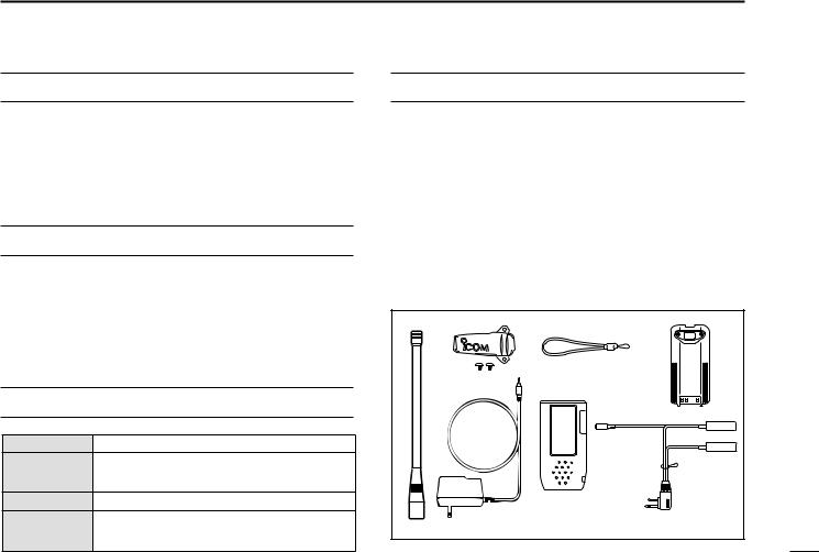
SUPPLIED ACCESSORIES
Accessories included with the transceiver: |
Qty. |
q Antenna .......................................................................... |
1 |
w Belt clip ........................................................................... |
1 |
e Handstrap ....................................................................... |
1 |
r Battery pack* or battery case .......................................... |
1 |
t Wall charger* .................................................................. |
1 |
y Carrying case* ................................................................ |
1 |
u Headset adapter* ........................................................... |
1 |
*The battery pack, wall charger, headset adapter or carrying case may differ depending on version. Some versions do not include a battery pack, wall charger, headset adapter or carrying case.
q |
w |
e |
r |
|
t |
y |
|
|
|
|
u |
ii

PRECAUTION
RWARNING! NEVER hold the transceiver so that the antenna is very close to, or touching exposed parts of the body, especially the face or eyes, while transmitting. The transceiver will perform best if the microphone is 5 to 10 cm away from the lips and the transceiver is vertical.
RWARNING! NEVER operate the transceiver with a headset or other audio accessories at high volume levels. Hearing experts advise against continuous high volume operation. If you experience a ringing in your ears, reduce the volume level or discontinue use.
NEVER connect the transceiver to an AC outlet or to a power source of more than 11.5 V DC. Such a connection will damage the transceiver.
NEVER connect the transceiver to a power source that is DC fused at more than 5 A. Accidental reverse connection will be protected by this fuse, higher fuse values will not give any protection against such accidents and the transceiver will be ruined.
NEVER short the terminals of the battery pack. Also, current may flow into nearby metal objects, such as a necklace, etc. Therefore, be careful when carrying with, or placing near metal objects, carrying in handbags, etc.
DO NOT allow children to play with any radio equipment containing a transmitter.
DO NOT operate the transceiver near unshielded electrical blasting caps or in an explosive atmosphere.
AVOID using or placing the transceiver in direct sunlight or in areas with temperatures below –10°C (+14°F) or above +60°C (+140°F).
The use of non-Icom battery packs/chargers may impair transceiver performance and invalidate the warranty.
Even when the transceiver power is OFF, a slight current still flows in the circuits. Remove the battery pack or case from the transceiver when not using it for a long time. Otherwise, the battery pack or installed dry cell batteries will become exhausted.
FCC caution: Changes or modifications to this transceiver, not expressly approved by Icom Inc., could void your authority to operate this transceiver under FCC regulations. (U.S.A. only)
Icom, Icom Inc. and the 
 logo are registered trademarks of Icom Incorporated (Japan) in the United States, the United Kingdom, Germany, France, Spain, Russia and/or other countries.
iii

TABLE OF CONTENTS
SAFETY TRAINING INFORMATION ............................................... |
i |
|
FOREWORD ................................................................................... |
ii |
|
IMPORTANT .................................................................................... |
ii |
|
EXPLICIT DEFINITIONS ................................................................. |
ii |
|
SUPPLIED ACCESSORIES ............................................................ |
ii |
|
PRECAUTIONS............................................................................... |
iii |
|
TABLE OF CONTENTS ................................................................. |
iv |
|
1 |
PANEL DESCRIPTION ........................................................ |
1 – 6 |
|
■Panel description ................................................................... |
1 |
|
■Function display ..................................................................... |
5 |
2 |
ACCESSORY ATTACHMENT .................................................. |
7 |
3 |
BASIC OPERATION .......................................................... |
8 – 11 |
|
■Setting a frequency ................................................................ |
8 |
|
■Setting a squelch level ........................................................... |
8 |
|
■Selecting a weather channel................................................... |
8 |
|
■Receiving ............................................................................... |
9 |
|
■Transmitting ........................................................................... |
9 |
|
■ANL function ........................................................................... |
9 |
|
■Low battery indicator ............................................................ |
10 |
|
■Recall function ..................................................................... |
10 |
|
■Setting weather alert function................................................ |
11 |
|
■Accessing 121.5 MHz emergency frequency ....................... |
11 |
|
■Lock function ........................................................................ |
11 |
|
■Side tone function ................................................................ |
11 |
|
■Setting beep tone ................................................................. |
11 |
|
■Backlighting .......................................................................... |
11 |
4 |
MEMORY OPERATION ................................................... |
12 – 15 |
|
■Memory channel selection ................................................... |
12 |
|
■Transferring memory contents ............................................. |
12 |
|
■Programming a memory channel ......................................... |
13 |
|
■Memory names .................................................................... |
14 |
|
■Clearing the memory contents ............................................. |
14 |
5 |
SCAN OPERATION ......................................................... |
16 – 17 |
|
■Scan types ........................................................................... |
16 |
|
■COM band scan ................................................................... |
16 |
|
■Memory scan ....................................................................... |
16 |
|
■Weather channel scan (U.S.A. version only) ............................ |
17 |
|
■“TAG” channels ................................................................... |
17 |
6 |
VOR NAVIGATION (IC-A24 only) .................................... |
18 – 24 |
|
■VOR indications ................................................................... |
18 |
|
■VOR functions ...................................................................... |
19 |
|
■Flying to a VOR station ........................................................ |
20 |
|
■Entering a desired course .................................................... |
22 |
|
■Crosschecking position ........................................................ |
22 |
|
■Duplex operation (U.S.A. version only) .................................... |
24 |
7 |
BATTERY PACKS ........................................................... |
25 – 27 |
|
■Battery charging ................................................................... |
25 |
|
■Battery cautions ................................................................... |
25 |
|
■Optional battery case ........................................................... |
26 |
|
■Optional battery chargers ..................................................... |
27 |
8 |
CLONING ................................................................................ |
28 |
9 |
TROUBLESHOOTING ............................................................ |
29 |
10 |
SPECIFICATIONS .................................................................. |
30 |
11 |
OPTIONS ................................................................................ |
31 |
12 |
QUICK REFERENCE ...................................................... |
32 – 33 |
13 |
OPTIONAL HEADSET CONNECTION .................................. |
34 |
iv

 1 PANEL DESCRIPTION
■ Panel description |
||
e |
r |
t |
|
|
y |
|
|
u |
|
|
i |
w |
|
o |
|
|
|
q |
|
|
|
|
!0 |
!7 |
|
!1 |
|
!2 |
|
|
|
|
!6 |
|
!3 |
|
Microphone |
|
!5 |
|
|
|
|
|
Speaker |
|
!4 |
|
|
|
IC-A24
WX-ALERT
!7
IC-A6
WX-ALERT
!7
1
q BACKLIGHT SWITCH [LIGHT] (p. 11)
Turns the backlight for display and keypad ON or OFF.
w PTT SWITCH [PTT] (p. 9)
Push and hold to transmit; release to receive.
• “ ” appears on the function display while transmitting.
e VOLUME [VOL] (p. 9)
Adjusts the audio level.
r TUNING DIAL [DIAL] (pgs. 8–12)
Rotate [DIAL] to select the desired frequency, WX channel number, BANK number and memory channel.
Rotate [DIAL] to set the squelch level and beep tone level.
t ANTENNA CONNECTOR [ANT] (p. 7)
Connects the supplied antenna.
yRECALL CHANNEL UP/DOWN KEYS [Ω]/[≈] (p. 10)
Push to enter the recall function mode.
Push to call the stored frequency in the recall mode.
Push  , then push [Ω]/[≈]to replace stored recall frequencies to back or front.
PANEL DESCRIPTION |
1 |
u SQUELCH KEY [SQL•WX-ALERT] (p. 8) |
1 |
Push [SQL•WX-ALERT], then rotate [DIAL] to select the squelch level.
•24 squelch levels and squelch open (0) are available.
Push  , then push [SQL•WX-ALERT] to turn the WX-alert function ON or OFF.
iPOWER SWITCH [PWR] (pgs. 9, 28)
 Push and hold for 2 sec. to turn the power ON or OFF.
While pushing and holding [MR•MW], push [PWR] to enter the cloning function mode.
o EXTERNAL SPEAKER AND MICROPHONE JACKS [MIC/SP] (p. 34)
Connects an OPC-499 HEADSET ADAPTER and headset, if desired.
!0FUNCTION KEY 
Push to call up the function indicator, “ ”, then push another key to access its secondary function.
•“ ” appears for 3 sec. after
  is pushed; at this time pushing
  again cancels the indication.
NOTE: In general, “ ” disappears when another key is pushed to activate a secondary function. However, some keys which have more than one secondary function, (such as [DUP]), do not cancel “
 ”. In this case, “
 ” disappears automatically after 3 sec.
2
1 PANEL DESCRIPTION
!1CLEAR KEY [CLR•DEL] (pgs. 8–17)
Push to turn to the frequency mode, when memory channel, WX channel, 121.5 MHz, squelch level setting or beep tone setting is selected.
Push  , then push and hold [CLR•DEL] to delete a recall frequency data.
Push to clear the entered comment of memory name while programming.
Push to stop the scan function to turn to the frequency mode while the scan function is operating.
!2ANL KEY [ANL•SCAN] (pgs. 9, 16, 17)
Push to turn the ANL function ON or OFF.
Push  , then push [ANL•SCAN] to start the scan function.
!3EMERGENCY KEY [121.5 MHz] (p. 11)
Push for 2 sec. to select the 121.5 MHz emergency frequency.
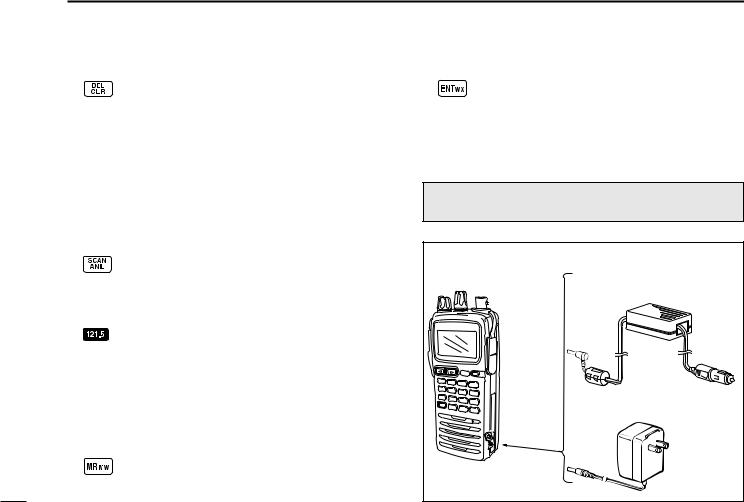
!4DC POWER JACK
Connect the AC adapter or optional cable to charge the battery pack or to operate by external power supply. (see right illustration)
!5MEMORY MODE KEY [MR•MW] (pgs. 12–15)
Push to call the memory channel mode.
Push  , then push [MR•MW] to program the contents into the memory channels.
!6ENTER KEY [ENT•WX] (pgs. 8, 14)
Push to enter the numeral input. Enters consecutive zero digits. (p. 8)
Push  , then push [ENT•WX] to enter the weather channel selection mode (U.S.A. version only). (p. 8)
Push to program the memory name. (p. 14)
NOTE: Some functions may not be available depending on versions. Ask your authorized dealer for details.
• DC POWER CONNECTION
IC-A24/A6 |
CP-20 (for 11 24 V) |
|
(optional) |
To the cigarette lighter socket
To [DC 11V]
Wall charger
3

!7DIGIT KEYS
Input the specified digit during frequency input, memory channel selection, etc.
In addition, each key has one or more secondary function after pushing  as follows:
Push  , then push [0•BANK] to select the memory BANK number to rotate [DIAL] on the memory operation. (p. 12)
Push  , then push [1•DVOR] to select the DVOR display from the CDI display in NAV band. (p. 19)*1
Push  , then push [2•TO] to change the course indicator characteristics to “TO” flag in the DVOR display in NAV band. (p. 19)*1
Corrects the deviation while using “TO” flag. *1
Push  , then push [3•FROM] to change the course indicator characteristics to “FROM” flag in the DVOR display in NAV band. (p. 19)*1
Corrects the deviation while using “FROM” flag. *1
Push  , then push [4•CDI] to select the CDI display from the CDI display in NAV band. (p. 19)*1
PANEL DESCRIPTION 1
Push  , then push [5•DUP-W] to set the duplex 1 frequency in NAV band for U.S.A. version only.
(p. 24)*1
Push  , then push [6•DUP] to turn the duplex function ON and OFF in NAV band for U.S.A. version only. (p. 24)*1
Push  , then push [7•
 ] to turn the key lock function ON and OFF. (p. 11)
Push  , then push [8•BEEP] to turn the beep tone setting mode ON (p. 11).
• Adjustable level; 0 to 9
Push  , then push [9•TAG] to set the displayed memory or weather channel as a “TAG” channel. (p. 17)
*1 These functions available on the IC-A24 only.
4
1 PANEL DESCRIPTION
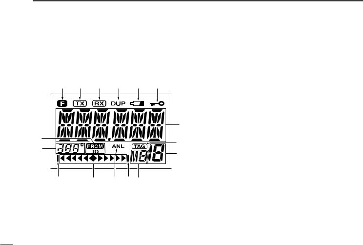
■ Function display
q |
w |
e |
r |
t |
y |
|
|
|
|
|
u |
!5 |
|
|
|
|
i |
!4 |
|
|
|
|
|
|
|
|
|
o |
|
|
|
|
|
|
|
!1 |
|
!3 |
!2 !1!0 |
|
|
q FUNCTION INDICATOR (p. 2)
Appears when  is pushed.
w TX INDICATOR (p. 9)
Appears while transmitting.
e RX INDICATOR (p. 9)
Appears when receiving a signal or when the squelch opens.
r DUPLEX INDICATOR (IC-A24 only) (p. 24)
“DUP” appears when the duplex function is activated in NAV mode.
“DUP” blinks while setting the duplex frequency.
t LOW BATTERY INDICATOR (p. 10)
Appears when the battery is nearing exhaustion. The attached battery pack requires recharging.
Appears and flashes when battery replacement is necessary.
y LOCK INDICATOR (p. 11)
Appears while the lock function is in use.
u FREQUENCY DISPLAY (pgs. 8, 14)
Shows the operating frequency.
Shows the channel name when the memory name function is selected.
5
i TAG CHANNEL INDICATOR (p. 17)
“ ” appears when the memory channel is set as a TAG channel.
o MEMORY CHANNEL INDICATOR (pgs. 12–15) Shows the memory channel number.
!0MEMORY BANK NUMBER INDICATOR (p. 12) Shows the selected memory bank number.
!1OVERFLOW INDICATOR (IC-A24 only) (pgs. 18–22) Appears when the deviation between the desired course and flying course is over 10 degrees.
!2ANL INDICATOR (p. 9)
Appears while the ANL (Automatic Noise Limiter) function is in use.
!3COURSE DEVIATION NEEDLES (IC-A24 only) (pgs. 18–22)
Indicates the deviation between the desired course and your actual flying course every 2 degrees.
PANEL DESCRIPTION 1
1
!4COURSE INDICATORS (IC-A24 only) (p. 19)
Indicates where your aircraft is located on a VOR radial in DVOR mode.
Indicates where your desired course is located on a VOR radial in CDI mode.
!5TO-FROM INDICATOR (IC-A24 only) (p. 19)
Indicates whether the VOR navigation information is based on a course leading to the VOR station or leading away from the VOR station.
6
 2 ACCESSORY ATTACHMENT
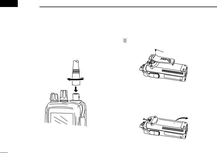
DAntenna
CAUTION: DO NOT transmit without an antenna. Otherwise the transceiver may be damaged.
Insert the supplied antenna into the antenna connector and screw down the antenna as shown below.
DBelt clip
Conveniently attaches to your belt.
Attach the belt clip with the supplied screws as below. NOTE: Use the supplied screws only.

 Supplied screws
DBattery pack replacement
Before replacing the battery pack, push [PWR] for 2 sec. to turn the power OFF.
Slide the battery release button forward, then pull the battery pack upward with the transceiver facing away from you.
7
 Loading...