


IC-2800H

INSTRUCTION MANUAL
This device complies with Part 15 of the FCC rules.Operation is subject to the following two conditions: (1) This device may not cause
harmful interference, and (2) this device must accept an y interference
received, including interference that may cause undesired operation.
i2800H
DUAL BAND FM TRANSCEIVER
Downloaded by
Amateur Radio Directory
www.hamdirectory.info
i
FOREWORD
READ ALL INSTRUCTIONS carefully and completely
before using the transceiver.
SA VE THIS INSTRUCTION MANUAL — This in-
struction manual contains important operating instructions for
the IC-2800H.
EXPLICIT DEFINITIONS
The explicit definitions below apply to this instruction manual.
CA UTIONS
RWARNING! NEVER connect the tr ansceiver to an AC
outlet. This may pose a fire hazard or result in an electric
shock.
RWARNING! NEVER oper ate the transceiv er while dri-
ving a vehicle. Safe driving requires your full attention—anything less may result in an accident.
RWARNING! HIGH VOLTAGE! NEVER disassem-
ble the remote controller .There is a high voltage circuit inside.
NEVER connect the transceiver to a power source of more
than 16 V DC or using reverse polarity.This will ruin the transceiver .
NEVER cut the DC power cable between the DC plug and
fuse holder. If an incorrect connection is made after cutting,
the transceiver may be damaged.
NEVER place the transceiver where normal operation of the
vehicle may be hindered or where it could cause bodily injury.
NEVER let objects impede the operation of the cooling fan
on the rear panel.
DO NOT push the PTT when not actually desiring to trans-
mit.
WORD
R
WARNING
CAUTION
NOTE
DEFINITION
Personal injury, fire hazard or electric
shock may occur.
If disregarded, inconvenience only. No risk
of personal injury, fire or electric shock.
Equipment damage may occur.
Versions of the IC-2800H which display the “CE” symbol on the serial number seal comply with the European harmonised standard
ETS300 684 (EMC product standard for Commercially Available
Amateur Radio Equipment).

ii
DO NOT operate the transceiver near unshielded electrical
blasting caps or in an explosive atmosphere.
During mobile operation,
DO NOT operate the transceiver
without running the vehicle’s engine .When transceiv er po w er
is ON and your vehicle’s engine is OFF, the vehicle’s battery
will soon become exhausted.
AVOID using or placing the transceiver in direct sunlight or
in areas with temperatures below –10°C (+14°F) or above
+60°C (+140°F).
AVOIDthe use of chemical agents such as benzine or alco-
hol when cleaning, as they can damage the transceiver’s surfaces.
Place unit in a secure place to avoid inadvertent use by children.
BE CAREFUL! The transceiver will become hot when op-
erating it continuously for long periods.
USE Icom microphones only (supplied or optional). Other
manufacturer’s microphones have different pin assignments
and may damage the transceiver if attached.
For LCD display
DO NOT press the LCD screen. Excessive pressure may
cause permanent damage to the LCD.
DO NOT tap or scratch the LCD using sharp objects.
BE CAREFUL when cleaning the LCD. Dust can easily
scratch the surface.
LCDs are produced using high-density manufacturing tech-
nology resulting in 99.98% active dots, however, up to 0.02%
of the dots may be non-active and/or continuously activ e .This
is normal and does not indicate LCD malfunction.
Uneven areas may be displayed depending on display contents in some cases.
After displaying the same screen continuously for long periods, image ‘b urn-in’may occur .In such cases, turn the power
OFF and discontinue operation for at least 24 hours.
For U.S.A. only
CAUTION:Changes or modifications to this device, not ex-
pressly approved by Icom Inc., could void your authority to
operate this device under FCC regulations.

1 SUPPLIED ACCESSORIES ......... 1
2 PANEL DESCRIPTION ......... 2 –13
■Controller unit ......................... 2
■Function display ...................... 4
■Basic function menu ............... 6
■Main unit ................................. 8
■HM-98 microphone ............... 10
■HM-97/118 microphone ........ 13
3 INSTALLATION ................... 14 – 17
■Location ................................ 14
■Mounting with the mounting
bracket .................................. 14
■Mounting the remote
controller ............................... 15
■Battery connection ................ 15
■DC power supply
connection ............................ 16
■Cable connection .................. 16
■Antenna installation .............. 17
4 FREQUENCY SETTING ...... 18–22
■Preparation ........................... 18
■Lock functions ....................... 19
■Using the tuning dial ............. 20
■Using the [Y]/[Z] keys .......... 20
■Setting a tuning step ............. 21
■Using the keypad .................. 22
5 BASIC OPERATION ............ 23–25
■Receiving .............................. 23
■Monitor function .................... 24
■Audio mute function .............. 24
■Transmitting .......................... 24
■Selecting output power ......... 25
■One-touch PTT function ....... 25
6 REPEATER OPERATION .... 26 –31
■Accessing a repeater ............ 26
■1750 Hz tone ........................ 28
■Subaudible tone .................... 29
■Offset frequency ................... 30
■Auto repeater function .......... 31
7 MEMORY/CALL
CHANNELS ......................... 32– 39
■General ................................. 32
■Programming during
selection................................. 32
■Programming after selection.. 33
■Transferring memory contents
to another memory ............... 33
■Programming during selection
via the microphone ............... 34
■Programming after selection
via the microphone ............... 34
■Transferring memory contents
to another memory via the
microphone ........................... 35
■Memory clear ........................ 36
■Alphanumeric display ............ 37
■Call channel .......................... 38
8 SCRATCH PAD MEMORY... 40 –41
■What is a scratch pad
memory? ............................... 40
■Calling up a scratch pad
memory ................................. 40
■Transferring scratch pad
memory contents .................. 41
9 SCAN OPERATION ............. 42–46
■Scan types ............................ 42
■Full/programmed scan .......... 43
■Selecting scan edges ........... 44
■Memory scan ........................ 45
■Skip channel setting ............. 46
■Scan resume condition ......... 46
10 BAND SCOPE ............................ 47
■Operation .............................. 47
11 PRIORITY WA TCH .............. 48–49
■Priority watch types .............. 48
■Priority watch operation ........ 48
12 SUBAUDIBLE T ONE
OPERATION ........................ 50 – 53
■Tone squelch operation ......... 50
■Pocket beep operation .......... 52
■Tone scan ............................. 53
13 DTMF MEMORY .................. 54–56
■Programming a DTMF code.. 54
■Transmitting a DTMF code..... 55
■DTMF speed ......................... 56
14 WIRELESS OPERATION .... 57–62
■Connection ........................... 57
■HM-90 wireless microphone.. 57
■EX-1759 installation .............. 58
■HM-90 switches .................... 59
■Microphone address ............. 62
15 OTHER FUNCTIONS .......... 63–75
■Beep tones ........................... 63
■Time-out timer ....................... 63
■Auto power-off function ......... 64
■Cooling fan ............................ 64
■Squelch delay ....................... 65
■Sub band mute ..................... 65
■Sub band busy beep ............. 66
■Automatic RF attenuator ....... 66
■Memory name indication ...... 67
■HM-98 [F-1]/[F-2] keys .......... 67
■HM-97/118 [UP]/[DN] keys.... 68
■Display contrast .................... 68
■Display brightness ................ 69
■Indication type ...................... 69
■My call function ..................... 69
■Packet operation ................... 70
■Video monitor function .......... 73
■Demonstration display .......... 74
■AM/FM narrow mode ............ 74
■Fuse replacement ................. 74
■Partial reset .......................... 75
■All reset ................................. 75
16 CS-2800 CLONING
SOFTWARE ......................... 76–79
17 TROUBLESHOOTING ............... 80
18 OPTIONS .................................... 81
19 SPECIFICATIONS ............... 82 – 83
iii
TABLE OF CONTENTS
1
1
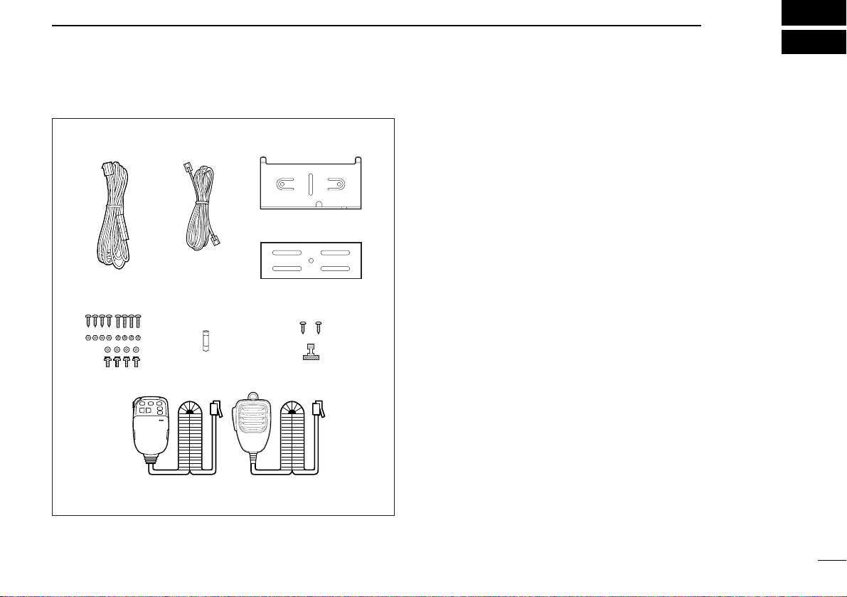
SUPPLIED ACCESSORIES
The transceiver comes with the following accessories. Qty.
q DC power cable (OPC-346) ........................................... 1
w Remote controller cable*
1
............................................... 1
e Remote controller mounting bracket (MB-73) ................. 1
r Main unit mounting bracket ............................................ 1
t Mounting screws, nuts and washers ......................... 1 set
y Fuse (FGB 20 A) ............................................................ 1
u Remote controller mounting screws and nut ............ 1 set
i Microphone*
2
(HM-98/97/118) ........................................ 1
*
1
A ferrite core is attached at one end of the cable for the
U.S.A., Europe, Taiwan and Italy versions.
*
2
The microphones illustrated at left are the HM-98 and
HM-118. One of either the HM-98, HM-97 or HM-118/T/TA
microphone is supplied depending on version.
q
e
r
w
ty u
i
HM-98 HM-118
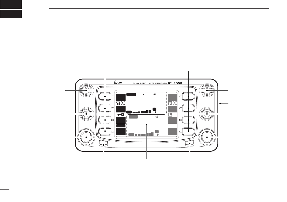
■ Controller unit
2
2
PANEL DESCRIPTION
MAIN
SCP
SCP
TS
V/M
H
TS
V/M
H
SCN
M/C
SCN
M/C
LOW
MONI
LOW
MONI
TOT
RX
TX
MID-LO
MID-LO
SUB
MAIN
DUP SQLTPRIO
DUP SQLTPRIO
OFF
M
P
M
P
99
14 5
5.000
99
43 5
3.000
VOL
VOL
SQL
SQL
CHG/L
POWER
MAIN
Function display (p. 4)
q
w
e
rt
y
u
o
!0!0
i
Downloaded by
Amateur Radio Directory
www.hamdirectory.info

3
2
PANEL DESCRIPTION
q VHF VOLUME CONTROL [VOL]
Adjusts the VHF audio level. (p.23)
w VHF SQUELCH CONTROL [SQL]
➥Adjusts the VHF squelch level. (p. 23)
➥Depending on the set mode setting, the RF attenuator
is automatically activated when [SQL] is rotated clockwise past the 12 o’clock position.(pgs. 23, 66)
e VHF TUNING DIAL [DIAL]
Rotate [DIAL] to set operating frequencies, memory channels, set mode contents, etc.(p. 20)
r CHANGE/LOCK SWITCH [CHG/L]
➥Toggles the multi-function switch menu.(p.6)
➥Push [CHG/L] for 2 sec. to toggle the lock function ON
and OFF.(p. 19)
t POWER SWITCH [POWER]
Push for 2 sec. to toggle the transceiver power ON and
OFF.(p. 18)
y UHF TUNING DIAL [DIAL]
Rotate [DIAL] to set operating frequencies, memory channels, set mode contents, etc.(p. 20)
u UHF SQUELCH CONTROL [SQL]
➥Adjusts the UHF squelch level. (p.23)
➥Depending on the set mode setting, the RF attenuator
is automatically activated when [SQL] is rotated clockwise past the 12 o’clock position.(pgs. 23, 66)
i VIDEO INPUT JACK [VIDEO IN]
Inputs an NTSC or PAL video signal depending on version.
(p.73)
o UHF VOLUME CONTROL [V OL]
Adjusts the UHF audio level.(p.23)
!0 MULTI-FUNCTION SWITCHES (pgs. 6, 7)
Push to select the function indicated in the right-hand or
left-hand LCD display of these switches.
•Left-hand switches are used for VHF band and right-hand
switches are used for UHF band.
•Functions vary depending on the operating condition.
4
2
PANEL DESCRIPTION
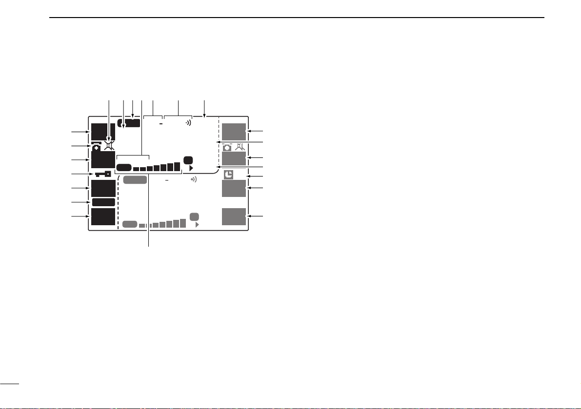
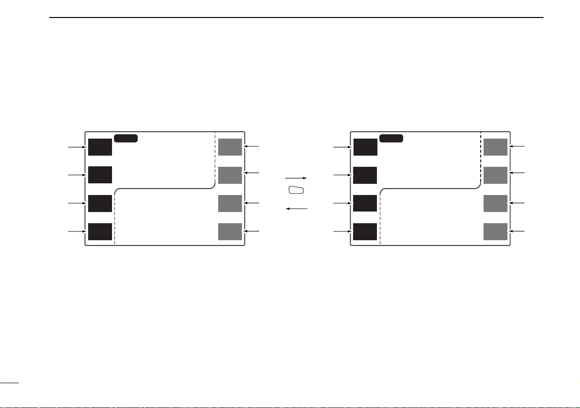
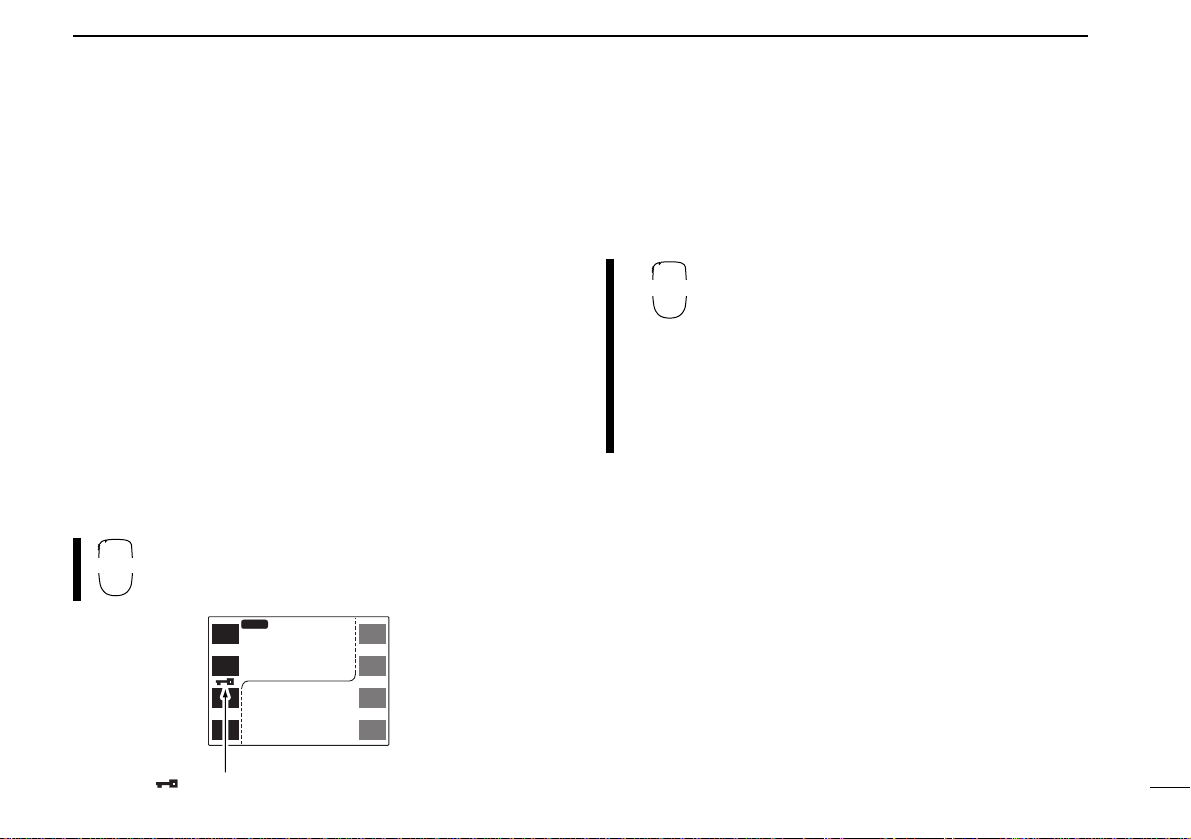
■ Function display
q FUNCTION INDICATORS (pgs.6, 7)
Indicate the functions assigned to the multi-function
switches at left.
w DTMF MEMORY ENCODER INDICATOR (p. 54)
Appears when the DTMF memory encoder is in use.
e LOCK INDICATOR (p.19)
Appears when the lock function is in use.
r TIME-OUT TIMER INDICA T OR (p.63)
➥Appears when the time-out timer is activated.
➥Flashes when the time-out time elapses and the trans-
mission is terminated.
t S/RF INDICATOR
Shows the relative signal strength while receiving. Shows
the relative output power while transmitting.(pgs. 23, 24)
• “RX” appears when receiving a signal or when the squelch is
open.
•“TX”appears when transmitting.
y FUNCTION INDICATORS (pgs.6, 7)
Indicate the functions assigned to the multi-function
switches at right.
u AUTO POWER-OFF INDICATOR (p.64)
Appears when the auto power-off function is in use.
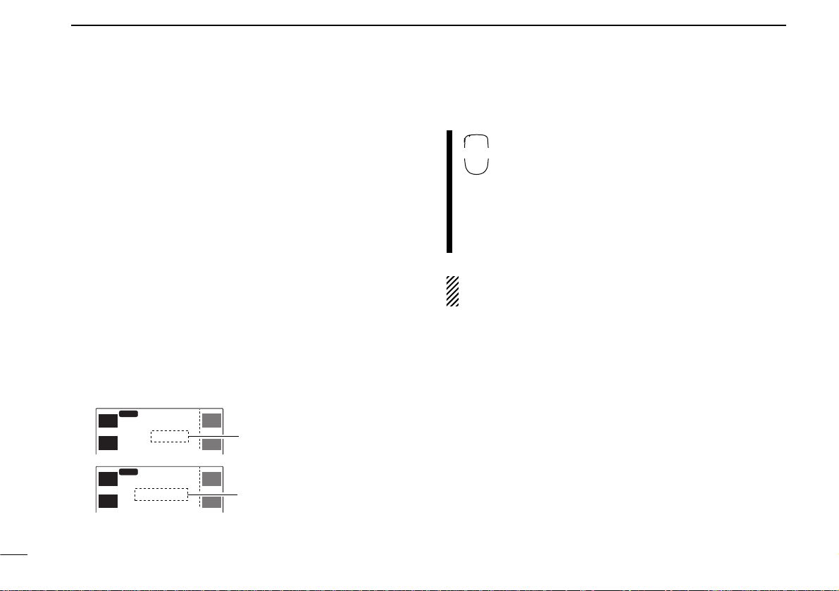
i MEMORY CHANNEL READOUT
Shows the memory or call channel number, etc.
➥“M”appears when a memory channel is selected.(p.18)
➥“≈” appears when a selected memory channel is set as
a skip channel. (p. 46)
➥“P≈” appears when the memory channel frequency is
set as a skip frequency during scanning. (p. 46)
MAIN
MAIN
SCP
SCP
V/M
H
TS
V/M
H
TS
M/C
SCN
M/C
SCN
MONI
LOW
MONI
LOW
TOT
RX
TX
MID-LO
MID-LO
SUB
MAIN
AM
DUP SQLTPRIO
DUP SQLTPRIO
OFF
M
P
M
P
99
43 5
3.000
99
14 5
5.000
q
q
q
r
q
w
e
t
i
y
y
u
y
y
o
!0!1!2!3!4!5!6

5
2
PANEL DESCRIPTION
o FREQUENCY READOUT
Shows the operating frequency, memory name, etc.
!0 PRIORITY WATCH INDICATOR (p.48)
Appears when priority watch is in use.
!1 TONE INDICATORS (pgs.26, 50, 52)
“T” appears when the subaudible tone encoder is in use;
“T SQLì” appears during pocket beep operation and
“T SQL” appears when the tone squelch function is activated.
!2 DUPLEX INDICATORS (p.26)
Appear when semi-duplex operation (repeater operation)
is in use.
•“DUP–”appears when minus duplex is selected;“DUP” appears
when plus duplex is selected.
!3 OUTPUT POWER INDICATORS (p.25)
➥“HI” appears when high output power is selected.
➥“MID-HI” appears when mid high output power is se-
lected
➥“MID-LO” appears when mid low output power is se-
lected
➥“LO” appears when low output power is selected
!4 MAIN BAND INDICATOR (p.18)
➥“Q” appears above the frequency which is selected
as the main band.
➥“^” appears when the sub band access function is
in use.
•This function can be used via the HM-98 and HM-90.
!5 AM/FM NARROW MODE INDICATOR (p.74)
➥“AM” appears when AM mode is selected.
• AM mode is available for the U.S.A.and S. America versions
only.
➥“NAR” appears when FM narrow mode is selected.
•FM narrow mode is available for the VHF band of the Europe
and Italy versions only.
!6 MUTE INDICATOR (pgs. 24, 65)
➥Both band’s indicators appear when the m ute function is
in use.
•This function can be used via the HM-98 and HM-90.
➥Sub band’s indicator appears when the sub band mute
function is activated.
6
2
PANEL DESCRIPTION
■ Basic function menu
The multi-function switches have 2 main menus. Pushing
[CHG/L] toggles between the 2 multi-function switch menus.
Left-hand switches are used for VHF band and right-hand
switches are used for UHF band except i and o.
MAIN
SCP
MAIN
SCP
V/M
H
TS
V/M
H
TS
M/C
SCN
M/C
SCN
MONI
LOW
MONI
LOW
MID-LO
MID-LO
MAIN
43
3.000
12
14
5.000
12
MID-LO
MID-LO
MAIN
43
3.000
12
14
5.000
12
MAIN
EDIT
EDIT
MAIN
S.MW
MW
S.MW
MW
DTMF
TON
DUP
TON
DUP
DISP
SET
CHG/L
q
w
e
r
r
e
w
q
t
y
u
i
o
u
y
t
q MAIN BAND/BAND SCOPE MENU [MAIN(SCP)]
➥Push to select the main band.(p. 18)
➥Push for 2 sec.to enter the band scope screen. (p.47)
w VFO/MHz/TUNING STEP MENU [V/M
H
(TS)]
➥Push to select VFO mode or to select the MHz tuning
step while in VFO mode.(p.20)
➥Push for 2 sec.to enter tuning step screen. (p.21)
e MEMORY CHANNEL/CALL CHANNEL/SCAN MENU
[M/C(SCN)]
➥Push to select the memory mode or call channel. (pgs.
18, 38)
➥Push for 2 sec.to enter the scan screen. (p.42)

7
2
PANEL DESCRIPTION
r MONITOR/LOW POWER MENU [MONI(LOW)]
➥Push to toggle the monitor function ON and OFF. (p.24)
➥Push for 2 sec.to change the output power selection.(p.
25)
•Low (LO), mid-low (MID-LO), mid-high (MID-HI) and high (HI)
powers are available.
t MAIN BAND/MEMORY EDIT MENU [MAIN(EDIT)]
➥Push to select the main band.(p. 18)
➥Push for 2 sec.to enter the edit screen. (pgs.29, 30, 37,
46, 51)
y TONE/DUPLEX MENU [TON(DUP)]
➥Push to activate the following functions in order.
•Subaudible tone encoder—“T”appears. (p. 26)
•Pocket beep—“T SQLì” appears.(p.52)
•Tone squelch—“T SQL” appears. (p.50)
•No tone operation—no indicator appears.
➥Push for 2 sec.to select semi-duplex or simplex opera-
tion. (p. 26)
• “DUP–” appears during minus duplex operation, “DUP” appears during plus duplex operation and no indicator appears
during simplex operation.
u SELECT MEMORY WRITE/MEMORY WRITE MENU
[S.MW(MW)]
➥Push to select the desired memory channel number to
be programmed.(p. 32)
➥Push for 2 sec. to program a memory channel or call
channel while in VFO mode.(p.32)
➥Push for 2 sec.to transfer a memory channel, call chan-
nel or scratch pad memory contents into the VFO when
not in VFO mode.(p.33)
i DTMF MENU [DTMF]
➥Push to toggle the DTMF memory ON and OFF.(p. 55)
➥Push for 2 sec. to enter the DTMF memory screen. (p.
54)
o DISPLAY/SET MODE MENU [DISP(SET)]
➥Push to enter the display set mode screen.(p. 68)
➥Push for 2 sec.to enter the set mode screen.
8
2
PANEL DESCRIPTION
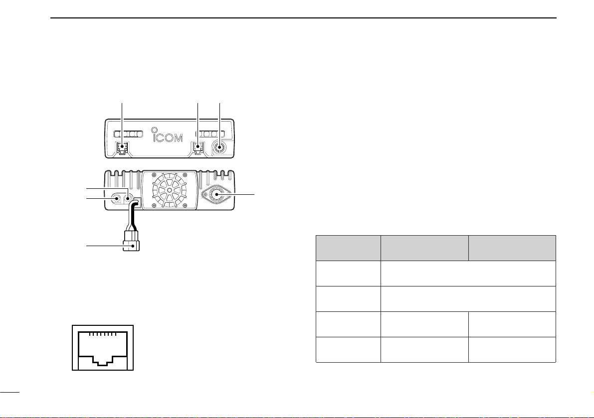
■ Main unit
q MICROPHONE CONNECTOR [MIC]
Connects the supplied microphone.
w CONTROLLER CONNECTOR [CONTROLLER] (p. 16)
Connects the controller unit with the supplied cable.
e DATA CONNECTOR [DATA] (p.70)
Connects a TNC (Ter minal Node Controller), etc. for data
communications.
•See the information at right for details.
r 144 MHz SPEAKER CONNECTOR [144 MHz SP]
Connects an 8 Ω speaker, if desired.
t 430(440) MHz SPEAKER CONNECTOR
[430(440) MHz SP]
Connects an 8 Ω speaker, if desired.
DATA
MIC CONTROLLER
qwe
t
r
y
u
q +8 V DC output (Max.10 mA)
w Frequency up/down
e HM-90/98 control input
r PTT
t Microphone ground
y Microphone input
u Ground
i No connection
➀➇
With no external speakers
[144MHz SP]
only
[430(440) MHz
SP] only
2 external
speakers
VHF band audio UHF band audio
Connected
speaker
Internal speaker (mixed audio)
External speaker (mixed audio)
Internal speaker
External speaker via
[144MHz SP]
External speaker via
[430(440) MHz SP]
External speaker
y POWER RECEPTACLE [DC13.8V] (pgs. 15, 16)
Accepts 13.8 V DC ±15% with the supplied DC power
cable.
•Current of 12 A or greater is required.
DO NOT use a cigarette lighter socket as a power
source when operating in a vehicle.The plug may cause
voltage drops and ignition noise may be superimposed
onto transmit or receive audio.
u ANTENNA CONNECTOR [ANT]
Connects a 50 Ω antenna with a PL-259 connector and a
50 Ω coaxial cable.
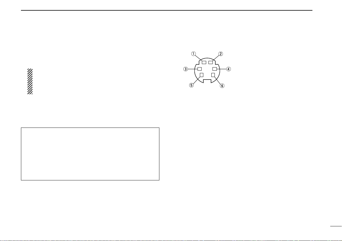
D DATA JACK PIN ASSIGNMENTS
q DATA IN
Input terminal for data transmit. See p. 70 for details on
how to toggle data speed between 1200 and 9600 bps.
w GND
Common ground for DATA IN, DATA OUT and AF OUT.
e PTTP
PTT terminal for packet operation only.Connect ground to
transmit data.
r DATA OUT
Data out terminal for 9600 bps operation only.
t AF OUT
Data out terminal for 1200 bps operation only.
y PSQL (squelch out)
Becomes high (+5V) when the transceiver receives a signal which opens the squelch.
•To avoid unnecessary TNC tr ansmission, connect squelch to the
TNC to inhibit transmission when receiving signals.
• Keep audio output at a normal level, otherwise a “P SQL” signal
will not be output.
9
2
PANEL DESCRIPTION
q DATA IN (1200 bps: AFSK
9600 bps: G3RUH, GMSK)
w GND
e PTTP
r DATA OUT (9600 bps)
t AF OUT (1200 bps)
y PSQL
ANTENNA INFORMATION
For radio communications, the antenna is of critical importance, along with output power and sensitivity. The transceiver accepts a 50 Ω antenna and less than 1.5 : 1 of
Voltage Standing Wave Ratio (VSWR). High SWR values
not only may damage the transceiv er but also lead to TVI or
BCI problems.
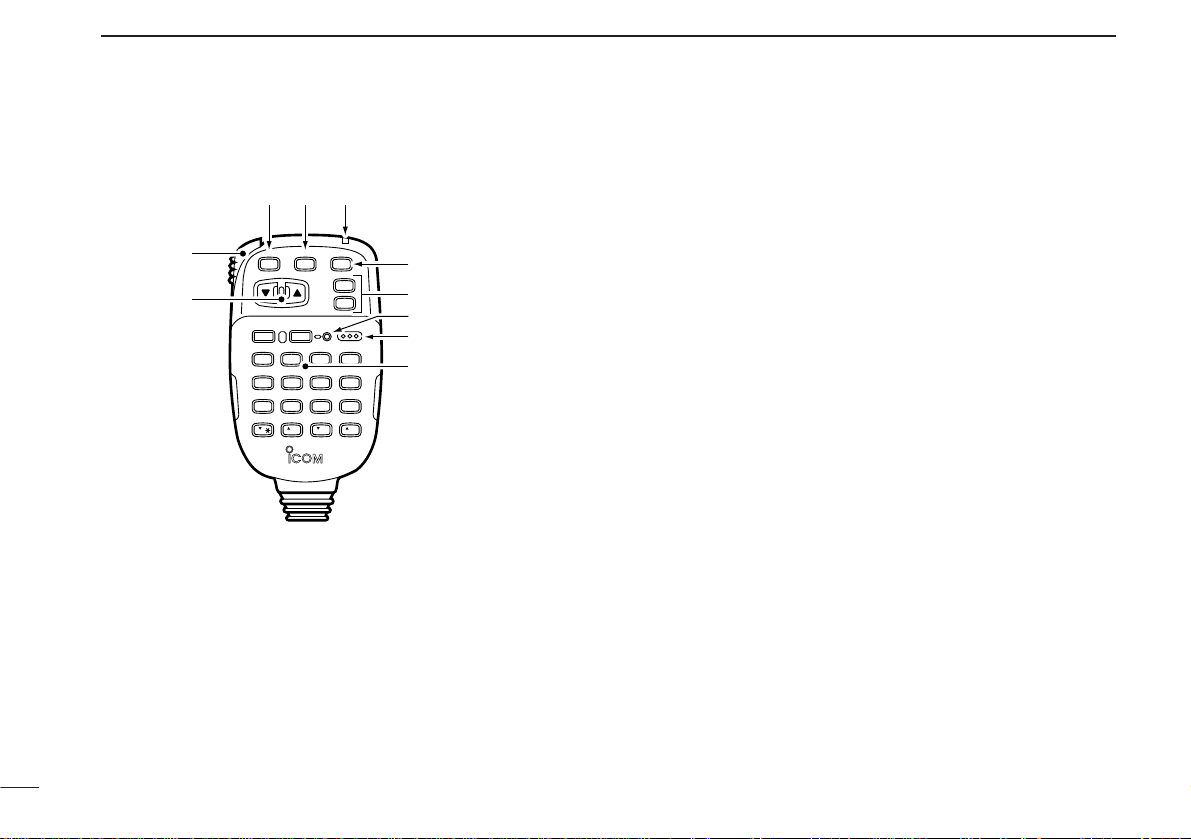
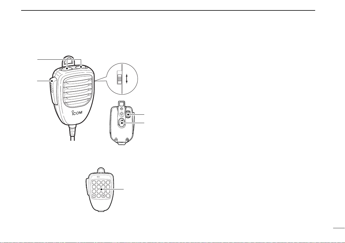
■ HM-98 microphone*
q UP/DOWN SWITCHES [YY]/[ZZ]
➥Push either switch to change the operating frequency,
memory channel, set mode contents, etc. (p. 20)
➥Push either switch for 2 sec. to start scanning. (p.43)
w PTT SWITCH
➥Push and hold to transmit;release to receive. (p.24)
➥Toggles between transmitting and receiving while the
one-touch PTT function is in use.(p. 25)
e VFO SWITCH [VFO(LOCK)]
➥Push to select VFO mode. (p.18)
➥Push for 2 sec.to toggle the lock function. (p. 19)
r MEMORY SWITCH [MR(CALL)]
➥Push to select memory mode.
➥Push for 2 sec.to select the call channel. (p.38)
t ACTIVITY INDICATOR
Lights red while a key is pushed; lights green while the
one-touch PTT function is in use.
y BAND SWITCH [BAND(SUB)] (p.18)
➥Push to toggle the operating band or set the sub band
as the main band.
➥Push for 2 sec.to toggle the sub band access function.
u FUNCTION SWITCHES [F-1]/[F-2] (p.67)
Assign your desired key function from the front panel
switches.
•Default settings are [VHF M/C] for [F-1] and [UHF M/C] for [F-2].
i FUNCTION INDICATOR
➥Lights orange while [FUNC] is activated—indicates the
secondary function of switches can be accessed.
➥Lights green when [DTMF-S] is activated—DTMF sig-
nals can be transmitted with the keypad.(p. 55)
o KEYPAD
Used for controlling the transceiv er, transmitting DTMF signals, etc.See the following 2 pages for details.
10
2
PANEL DESCRIPTION
LOCK
VFO
CALLMRSUB
BAND
MW
FUNC
A
CLR
D-OFF
B
SET
PTT-M
3
PRIO
DTMF
6
LOW
AFC-OFF
2
SCAN
CSQL
5
MID
AFC
1
MONI
PGR
4
HIGH
T-OFF
C
ENT
TSQL
9
SIMP
16
KEY LOCK
#
TSQLS
8
DUP+
TONE-2
0
TONE
7
DUP–
TONE-1
F-2
F-1
DTMF-S
MUTE
D
SQLSQLVOLVOL
Mic element
q
w
er t
y
u
i
o
*Some versions are
supplied with the
HM-97/118 instead.
11
2
PANEL DESCRIPTION
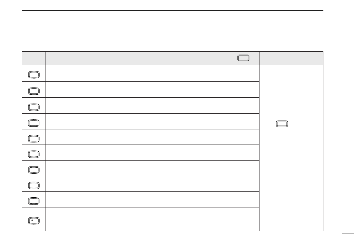
FUNC
DTMF-S
KEY FUNCTION
AFC
MONI
AFC-OFF
SCAN
PTT-M
PRIO
HIGH
CSQL
MID
DTMF
LOW
TONE
DUP–
TSQLS
DUP+
TSQL
SIMP
TONE-2
VOL
Toggles between opening and closing the
1
operating band’s squelch. (p. 24)
Starts and stops scanning. (p. 42) No secondary function.
2
Starts and stops priority watch. (p. 48)
3
PGR
Selects high output power. (p. 25) No secondary function.
4
Selects mid-high output power. (p. 25) No secondary function.
5
Selects low output power. (p. 25)
6
Selects –duplex. (p. 27)
7
Selects +duplex. (p. 27) Turns the pocket beep function ON. (p. 52)
8
Selects simplex. (p. 27) Turns the tone squelch function ON. (p. 50)
9
Increases the audio output. (p. 23)
• The [VOL] controls on the controller unit have
0
priority when rotated.
SECONDARY FUNCTION (after )
No secondary function.
Turns the one-touch PTT function ON and
OFF. (p. 25)
Turns the DTMF memory encoder function
ON. (p. 54)
Turns the subaudible tone encoder ON.
(p. 27)
While being pushed, transmits a 1750 Hz
tone. (p. 28)
OTHER FUNCTIONS
After :
Transmit the appropriate
DTMF code or push [0]
to [9], [A] to [D] to transmit the DTMF memory
contents when the
DTMF memory encoder
is activated. (p. 54)
12
2
PANEL DESCRIPTION
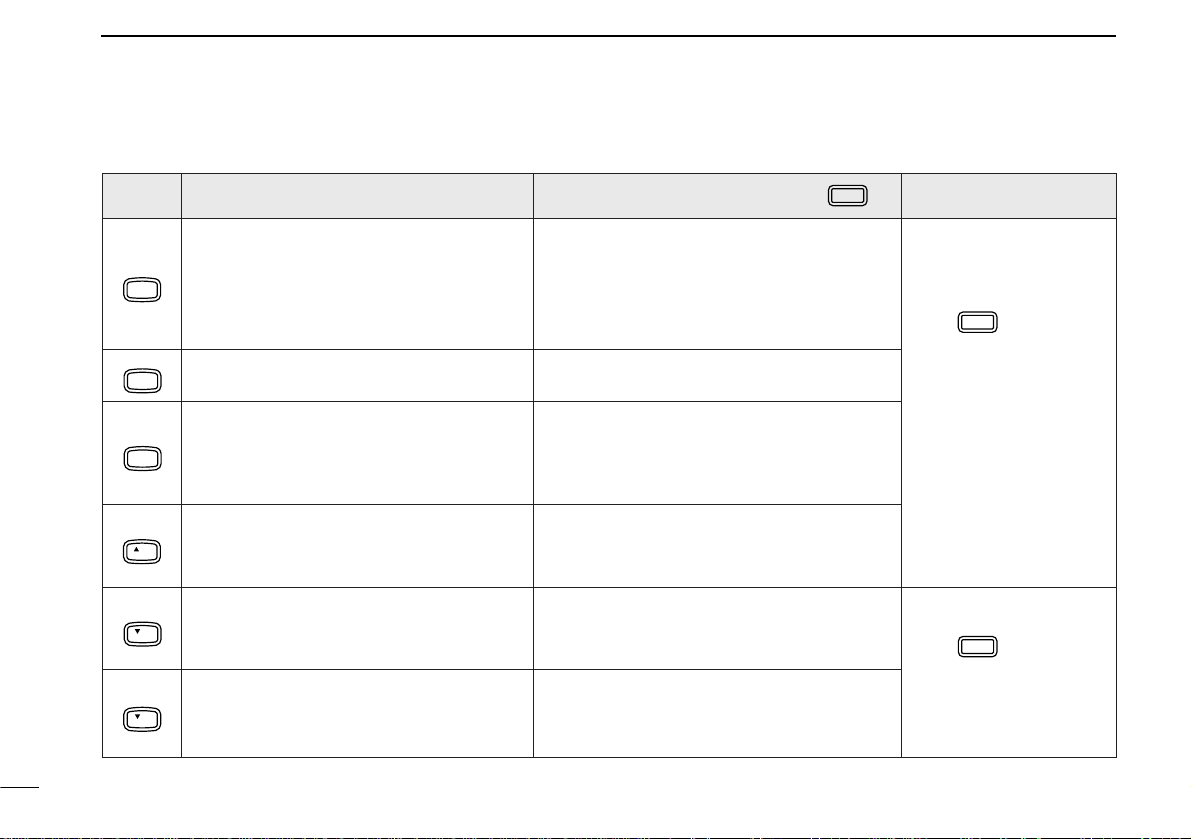
FUNC
DTMF-S
DTMF
KEY FUNCTION
•Clears a digit before entry. (p. 22)
•Cancels the monitor, scan, priority watch,
MW
CLR
D-OFF
SET
DTMF memory, mute function or set
A
mode condition. (pgs. 24, 42, 48, 54)
Enters set mode and decreases the set
B
mode selection order.
•Sets the keypad for numeral input.
T-OFF
ENT
C
•Advances the set mode selection order
after entering set mode.
MUTE
SQL
16
KEY LOCK
SQL
TONE-1
VOL
Increases the squelch level. (p. 23)
•The [SQL] controls on the controller unit have
D
priority when rotated.
Decreases the squelch level. (p. 23)
•The [SQL] controls on the controller unit have
#
priority when rotated.
Decreases the audio output. (p. 23)
•The [VOL] controls on the controller unit have
M
priority when rotated.
(p. 22)
SECONDARY FUNCTION (after )
•Writes the VFO contents into the memory
channel or call channel. (pgs. 34, 39)
•Advances the memory channel number
when continuously pushed after programming is completed. (p. 34)
DTMF memory OFF.
Turns the subaudible tone encoder, pocket
beep or tone squelch OFF. (pgs. 27, 50, 52)
Mutes both band’s audio. (p. 24)
•Mute function is released when any operation is
performed.
Locks the digit keys on the keypad (including
the A–D, # and
keys). (p. 19)
M
Sends a 1750 Hz tone signal for 0.5 sec.
(p. 28)
OTHER FUNCTIONS
After :
Transmit the appropriate
DTMF code or push [0]
to [9], [A] to [D] to transmit the DTMF memory
contents when the
DTMF memory encoder
is activated. (p. 54)
After :
Transmit the appropriate
DTMF code. (p. 54)
13
2
PANEL DESCRIPTION
■ HM-97/118 microphone
q PTT SWITCH
Push and hold to transmit; release to receive. (p.24)
w UP/DOWN SWITCHES [UP]/[DN]
➥Push either switch to change the operating frequency,
memory channel, set mode contents, etc. (p. 20)
➥Push either switch for 2 sec. to start scanning. (p.42)
➥Activate a function programmed in set mode. (p.68)
e LOCK SWITCH
Locks the [UP]/[DN] keys on the microphone.
r TONE SWITCH (HM-97 only)
Push to transmit a 1750 Hz tone call signal.(p. 28)
t DTMF KEYPAD (HM-118T/TA only)
Used for transmitting DTMF signals.
1 2 3 A
4 5 6 B
7 8 9 C
0 D
HM-97HM-118
HM-118T/TA
ON
OFF
q
w
e
e
r
t
Downloaded by
Amateur Radio Directory
www.hamdirectory.info
14
3
INSTALLATION
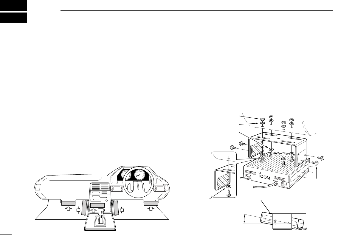
■ Location
Select a location which can support the weight of the transceiver and does not interfere with driving in any way. We recommend the locations shown in the diagram below.
NEVER place the transceiver or remote controller where normal operation of the vehicle may be hindered or where it
could cause bodily injury.
NEVER place the transceiver or remote controller where air
bag deployment may be obstructed.
DO NOT place the transceiver or remote controller where hot
or cold air blows directly onto it.
AVOID placing the transceiver or remote controller in direct
sunlight.
•EXAMPLE INSTALLATION LOCATIONS
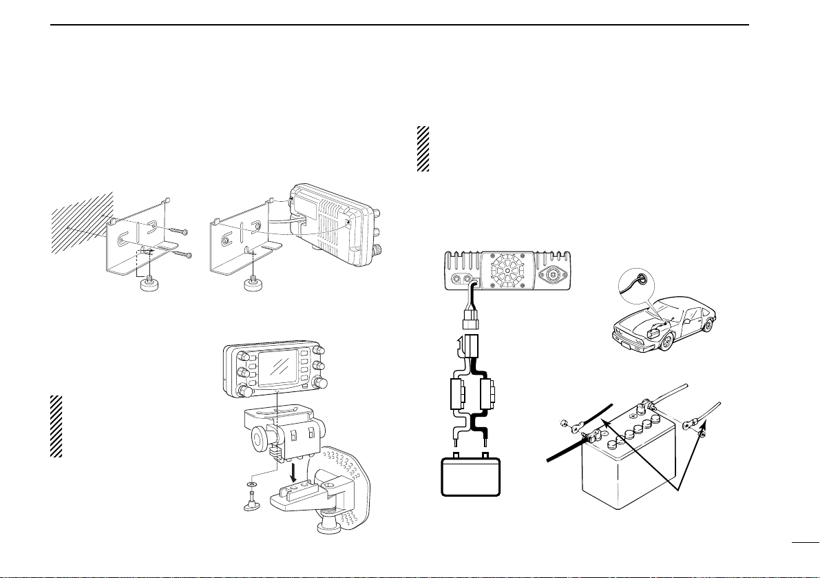
■ Mounting with the mounting
bracket
q Drill 4 holes where the mounting bracket is to be installed.
•Approx.5.5–6 mm (3⁄16˝) when using nuts;approx. 2–3 mm (1⁄16˝)
when using self-tapping screws.
w Insert the supplied screws, nuts and washers through the
mounting bracket and tighten.
e Adjust the angle, if desired.
Nut
Spring washer
When using
self-tapping
screws
Spring
washer
25°
Mounting
nut
Mounting
bracket
Flat washer
15
3
INSTALLATION
■ Mounting the remote
controller
Install the nut before attaching the bracket to the wall, etc.
D When using an
optional MB-65
The supplied remote controller bracket is not necessary when using the
optional MB-65.
■ Battery connection
NEVER connect the transceiver directly to a 24 V battery.
DO NOT use the cigarette lighter socket for power con-
nections.
Attach a rubber grommet when passing the DC power cable
through a metal plate to prevent short circuits.
•See p.74 for fuse replacement.
Nut Nut
MB-65
Remote
controller
12 V
Fuses
20 A
+ red
+ red
Grommet
_ black
_ black
Supplied
DC power cable
16
3
INSTALLATION
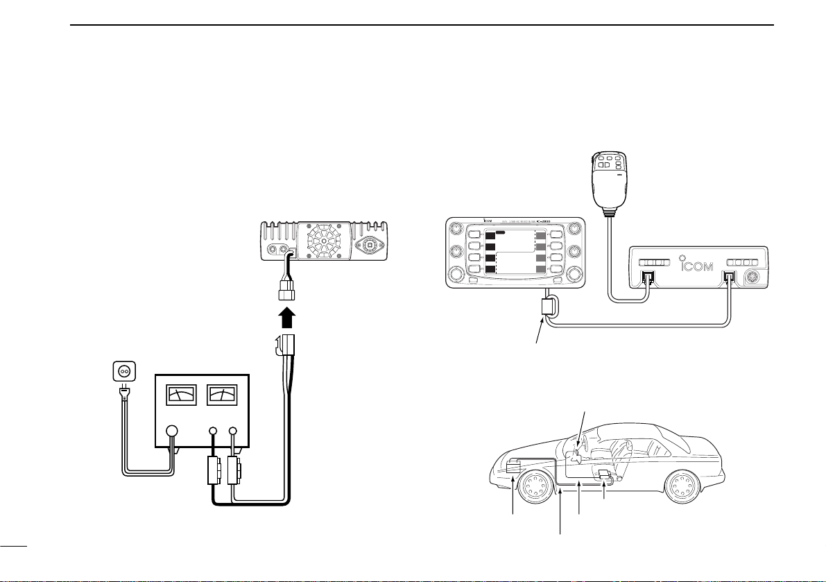
■ DC power supply connection
Use a 13.8 V DC power supply with more than 12 A capacity.
Make sure the ground terminal of the DC power supply is
grounded.
•See p.74 for fuse replacement.
■ Cable connection
Connect the cable as shown below.
DC power
supply 13.8 V
to an
AC
outlet
Fuses
20 A
+ red
+_
_ black
Battery
Remote controller
Remote controller cable
Power cable
Main unit
DATA
MIC CONTROLLER
MAIN
MAIN
SCP
SCP
V/M
H
TS
V/M
H
TS
M/C
SCN
M/C
SCN
MONI
LOW
MONI
LOW
HI
HI
MAIN
1
14
5.000
1
43
3.000
VOL
VOL
SQL
SQL
CHG/L
POWER
Remote controller
Speaker is
included in the
remote controller
Connect the end with the
ferrite core to the controller
(where applicable)
Supplied remote controller
cable (3.5 m, 11.5 ft)
IC-2800 main unit
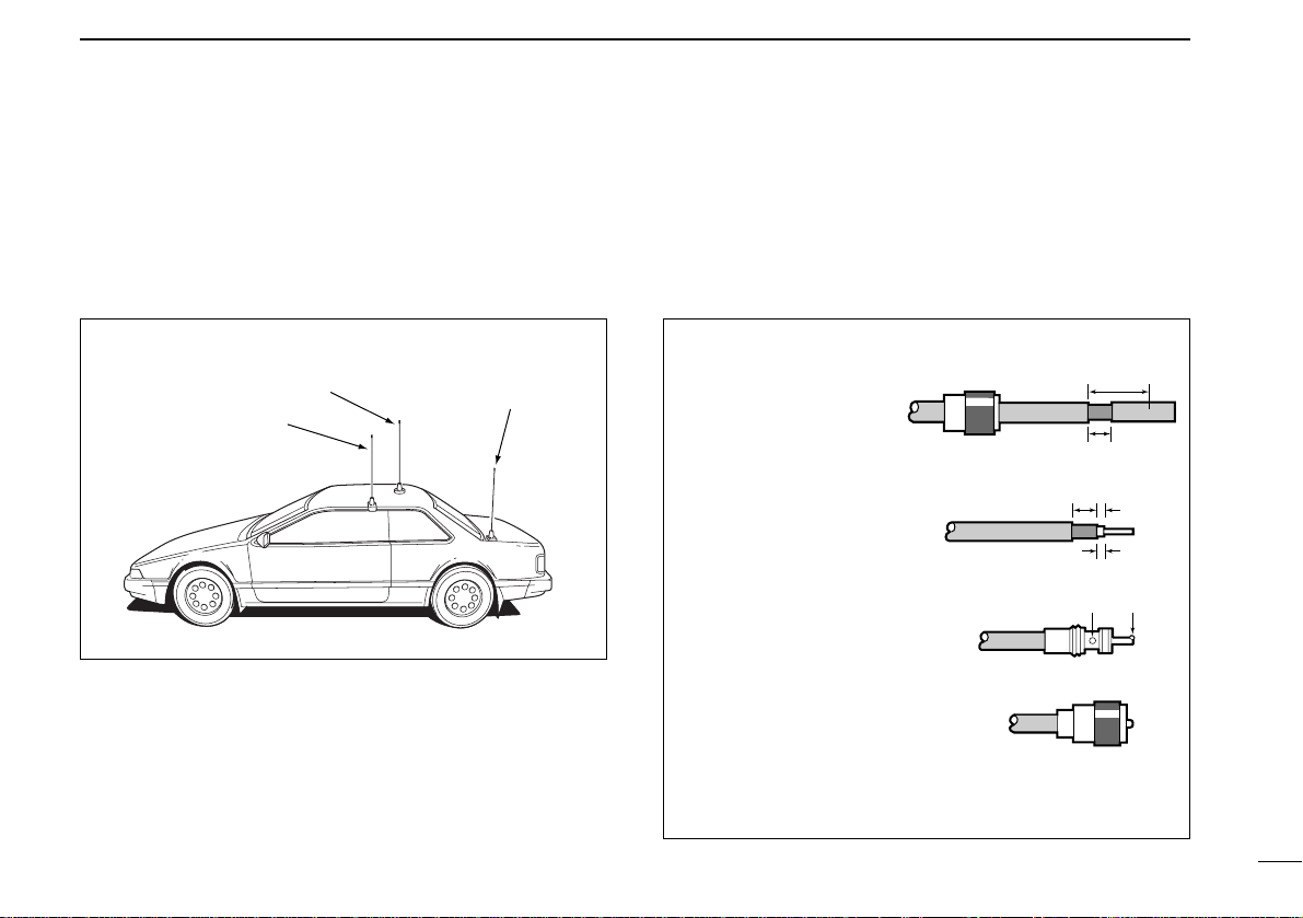
■ Antenna installation
D Antenna location
To obtain maximum performance from the transceiver, select
a high-quality antenna and mount it in a good location.A nonradial antenna should be used when using a magnetic mount.
D Antenna connector
The antenna uses a PL-259 connector.
17
3
INSTALLATION
Roof-mount antenna
(Drill a hole or use a magnetic mount.)
Trunk-mount
antenna
Gutter-mount antenna
•PL-259 CONNECTOR
q Slide the coupling ring
down. Strip the cable
jacket and soft solder.
w Strip the cable as
shown at right. Soft
solder the center conductor.
e Slide the connector
body on and solder it.
r Screw the coupling
ring onto the connector body.
(10 mm≈
3
⁄8 in)
Coupling ring
30 mm
10 mm (soft solder)
10 mm
Soft
solder
1–2 mm
solder solder
18
4
FREQUENCY SETTING
■ Preparation
D Turning power ON/OFF
Before operating the transceiver f or the first time it’s a good
idea to reset the transceiver’s CPU.This will ensure that all
transceiver settings are at their defaults.See p.75 for CPU
resetting details.
➥Push [POWER] for 2 sec.to turn power ON or OFF.
D Operating band
The transceiver can receive 144 MHz and 430(440) MHz
band signals simultaneously. To activate all functions or to
change frequency via the microphone, you must designate
one band as the main band. The transceiver can transmit a
signal on the main band only.
➥Push either [MAIN] to select the desired transmit band.
•“Q” indicator shows the selected band as the main band.
➥Push [BAND] to select the desired operating
band.
•“Q” indicator shows the selected band as the
main band.
D VFO and memory modes
The transceiver has 2 basic operating modes:VFO mode and
memory mode. Select VFO mode first to set an operating frequency.
➥Push [V/M
H
] to select VFO mode when the transceiver is
not in VFO mode.
• If VFO mode is already selected,
the digits below 100* kHz disappear. In this case, push [V/MH]
again (or push twice or 3 times depending on version).
* The digits below 1 or 10 MHz dis-
appear for some versions.
➥Push [VFO] to select VFO mode.
➥Push [MR] to select memory mode.
VFO
BAND
Note that in this manual, sections beginning with
a microphone icon (as above), designate operation via the HM-98 microphone.
[MAIN][MAIN]
[POWER]
MAIN
MAIN
SCP
5.000
14
V/M
H
MID-LO
TS
M
12
“M” appears in
memory mode.
MAIN
SCP
V/M
TS
H
■ Lock functions
To prevent accidental frequency changes and unnecessary
function access, use the lock function.The transceiver and
HM-98 have 2 diff erent lock functions.
D Frequency lock
This function locks the tuning dials and switches electronically
and also locks the microphone switches.
➥Push [CHG/L] for 2 sec.to toggle the frequency lock func-
tion ON and OFF.
• [CHG/L], [MAIN], [MONI], [VOL], [SQL], [PTT] and [BAND] can
be used while the frequency lock function is in use. Also,
TONE-1, TONE-2, DTMF tones or DTMF memory contents can
be transmitted from the HM-98 microphone.
➥Push [(VFO) LOCK] for 2 sec. to toggle the func-
tion ON and OFF.
D Microphone keypad lock
This function locks the HM-98 microphone keypad.
➥Push [FUNC] then [16KEY LOCK] to tog-
gle the microphone keypad lock function
ON and OFF.
• [PTT] and the 7 keys on the upper half of the
microphone can be used.
•All switches on the transceiver can be used.
•The keypad lock function is released when the
transceiver power is turned OFF then ON
again.
MID-LO
MAIN
43
3.000
12
14
5.000
12
SCP
MAIN
TS
V/M
H
SCN
M/C
LOW
MONI
SCP
MAIN
TS
V/M
H
SCN
M/C
LOW
MONI
MID-LO
“ ” appears when the lock function is in use.
19
4
FREQUENCY SETTING
LOCK
16 KEY LOCK
#
20
4
FREQUENCY SETTING
■ Using the tuning dial
q Select VFO mode with the desired band’s [V/MH].
•Push [CHG/L] if [V/MH] is not displayed.
w Rotate desired band’s [DIAL] to change the frequency.
• The frequency changes according to the selected tuning steps.
See the next page for selecting the tuning step.
D 1 MHz tuning step
Push the selected band’s [V/MH] to select 1 MHz tuning step.
Push [V/M
H
] again to return to the previous tuning step.
D 10 MHz and 1 MHz tuning steps
Push the selected band’s [V/MH] once or twice to select 10
MHz or 1 MHz tuning step, respectively. Push [V/M
H
] once or
twice to return to the previous tuning step.
Some versions do not have the 10 MHz tuning step.
■ Using the [Y]/[Z] keys
q Push [BAND] to select the desired band.
w Push [VFO] to select the VFO mode.
e Push [Y] or [Z] to select the desired frequency.
• The frequency changes according to the selected
tuning steps.(p. 21)
•Pushing [Y] or [Z] for more than 0.5 sec.activates
a scan. If this happens, push [Y] or [Z] again to
cancel the scan.
1 MHz or 10 MHz steps cannot be used via the [Y]/[Z]
keys.
MAIN
SCP
MAIN
SCP
V/M
H
TS
V/M
H
TS
MAIN
12
14
5.___
MAIN
SCP
MAIN
SCP
V/M
H
TS
V/M
H
TS
MAIN
12
14
_.___
While 1 MHz tuning step is
selected, the digits below
100 kHz disappear.
While 10 MHz tuning step is
selected, the digits below
1 MHz disappear.
Y Z
■ Setting a tuning step
Tuning steps can be selected for each band.This transceiver
has 8 tuning steps as follows:
•5 kHz •10 kHz •12.5 kHz •15 kHz •20 kHz
•25 kHz •30 kHz •50 kHz
q Select VFO mode with the desired band’s [V/M
H
].
•Push [CHG/L] if [V/MH] is not displayed.
w Push [(V/M
H
)TS] for 2 sec.to enter tuning step screen.
e Rotate desired band’s [DIAL] to select the desired tuning
step.
•Pushing [5], [20] or [25] also selects 5, 20 or 25 kHz tuning step.
r Push [í] to return to normal operation.
21
4
FREQUENCY SETTING
MAIN
43
3.000
14
5.000
12
í
5
20
25
SCP
MAIN
TS
V/M
H
SCN
M/C
LOW
MONI
TS = 5.0kTS = 5.0k
Return to previous menu
Shows 5 kHz tuning step is selected.
Select 5 kHz tuning step
Select 20 kHz tuning step
Select 25 kHz tuning step
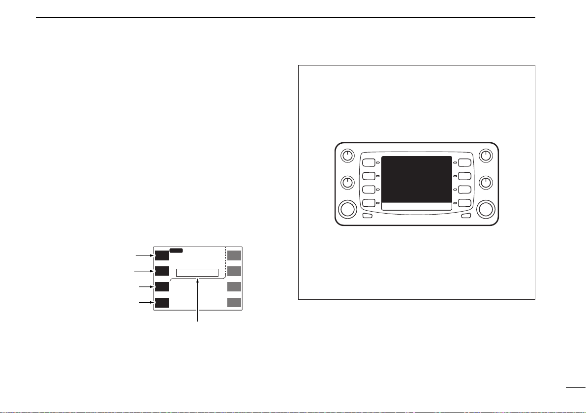
•Cloning mode information
The information in the transceiver, such as memory channels, memory names, etc.can be programmed using a PC.
The transceiver displays the following information when the
transceiver enters cloning mode for programming.
In the cloning mode, the [POWER] switch does not function. Push the [UP]/[DN] or [Y]/[Z] on the microphone to
return to the normal operating condition.
CLONE
Push mic UP/DN to EXIT.
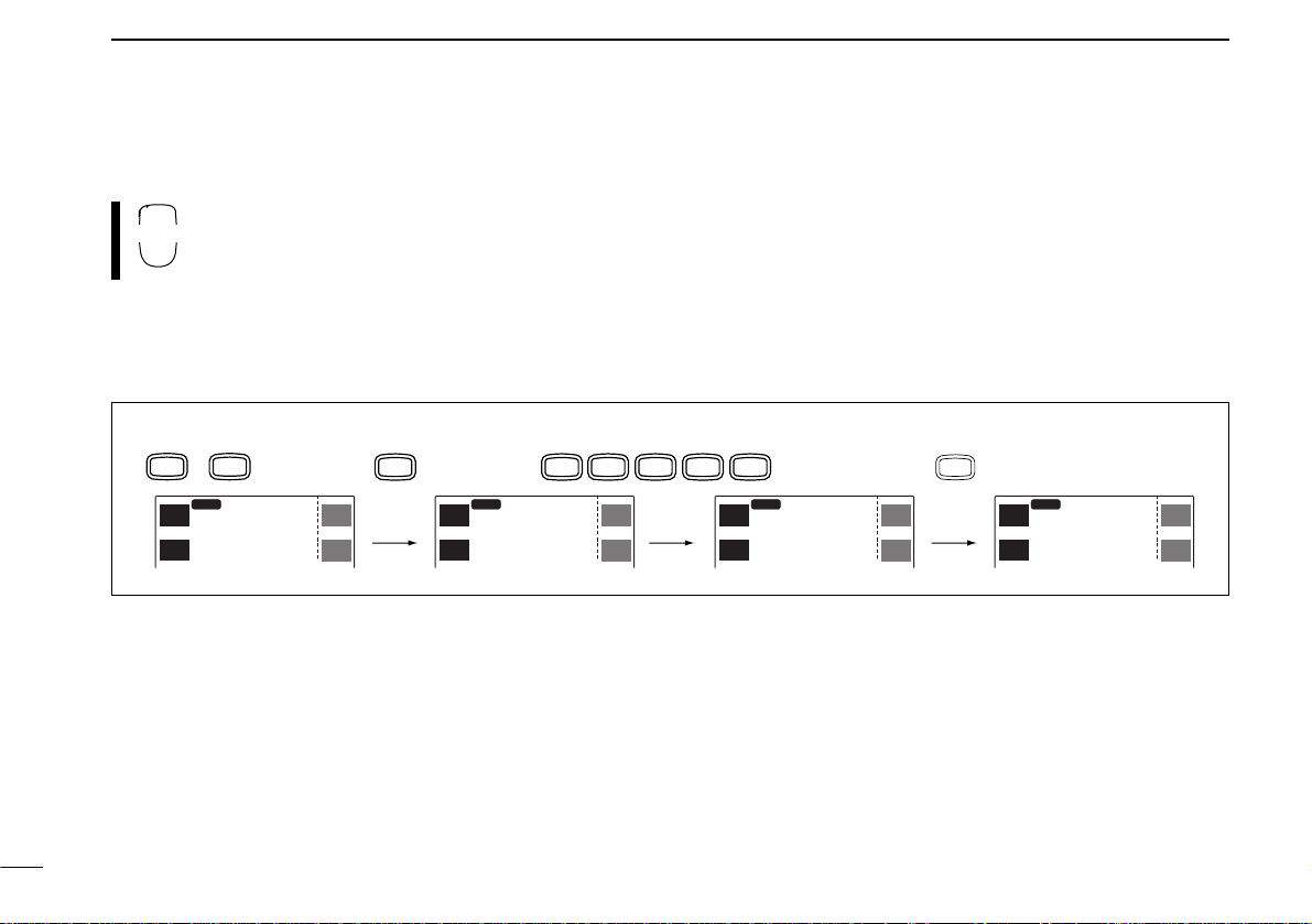
■ Using the keypad
The frequency can be directly set via numeral keys
on the HM-98 microphone.
q Push [BAND] to select the desired operating band.
w Push [VFO] to select VFO mode, if necessary.
e Push [ENT] to activate the keypad for digit input.
r Push 6 keys to input a frequency.
• When a digit is mistakenly input, push [ENT] to clear the input,
then repeat input from the 1st digit.
•Pushing [CLR] clears input digits and retrieves the frequency.
t Push [Y] or [Z] to make adjustments below the 10 kHz
digit, if desired.
22
4
FREQUENCY SETTING
ENT
C
[EXAMPLE]: Setting the frequency to 145.3625 MHz.
BAND
MAIN
SCP
V/M
MAIN
14
H
MID-LO
TS
VFO
5.000
12
MAIN
SCP
V/M
TS
ENT
C
MAIN
MAIN
SCP
V/M
H
H
MID-LO
TS
MONI4HIGH
5.
1
12
MAIN
SCP
V/M
TS
PRIO
MID
5
H
3
MAIN
SCP
V/M
TS
LOW
6
MAIN
5.36
14
H
MID-LO
12
MAIN
SCP
V/M
TS
SCAN
2
MAIN
MAIN
SCP
5.362
14
V/M
H
H
MID-LO
TS
5
12
MAIN
SCP
V/M
TS
H
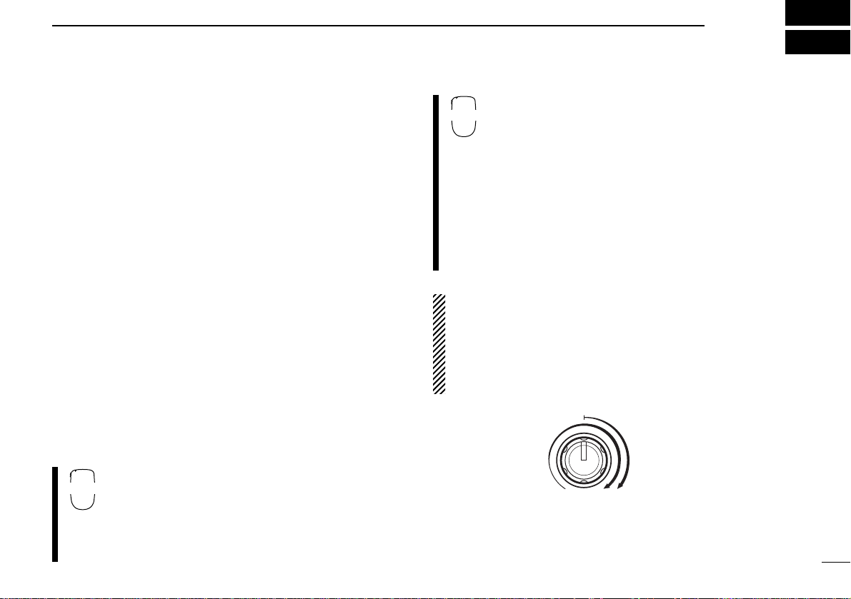
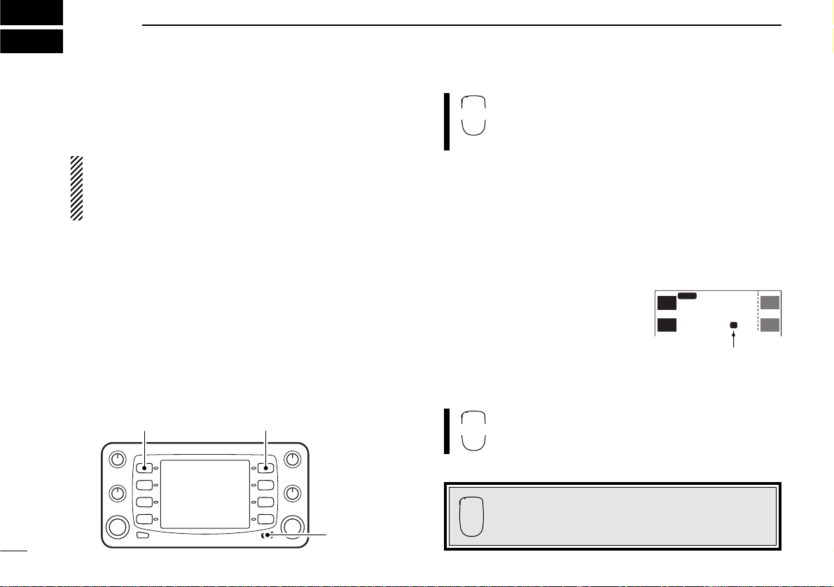
■ Receiving
q Push [POWER] for 2 sec.to turn power ON.
w Set the audio level.
➥Push the desired band’s [MONI] to open the squelch.
•Push [CHG/L] if [MONI] is not displayed.
➥Rotate the desired band’s [VOL] control to adjust the
audio output level.
➥Push [MONI] again to close the squelch.
e Set the squelch level.
➥Rotate the desired band’s [SQL] fully counterclockwise
in advance.
➥Rotate [SQL] clockwise until the noise just disappears.
➥When interference is received, rotate [SQL] clockwise
again for attenuator operation.
•Turn the automatic RF attenuator ON in advance.(p.66)
r Set the operating frequency. (p. 20)
t When receiving a signal on the set frequency, squelch
opens and the transceiver emits audio.
• “RX” appears and the S/RF indicator shows the relative signal
strength for the received signal.
q Push [POWER] for 2 sec. to turn power ON.
w Select the desired band with [BAND].
e Set the audio level.
➥Push [qMONI] to open the squelch.
➥Push [VOLY] or [VOLZ] to adjust the audio
output level.
•Volume level appears while setting.
➥Push [qMONI] again to close the squelch.
r Set the squelch level.
➥Push [SQLY] or [SQL Z] to set the squelch
to the point where noise just disappears.
•Squelch level appears while setting.
t Set the operating frequency.(p. 22)
y When receiving a signal on the set frequency,
squelch opens and the transceiver emits audio.
•“RX”appears and the S/RF indicator shows the relative signal strength for the received signal.
RF attenuator:
The transceiver has an RF attenuator related to the [SQL] setting. The attenuator is automatically
activated when [SQL] is rotated clockwise past the 12 o’clock position.Approx. 10 dB attenuation is obtained at full
rotation.Turn the automatic RF attenuator ON in advance
in set mode.(p. 66)
23
5
BASIC OPERATION
BAND
SQL
Y Z
0 dB
RF attenuatorSquelch
range
10 dB
 Loading...