


SERVICE AND INSTALLATION MANUAL
EF and EMF Series
Flaked ICE Machines
ICE-O-Matic |
|
11100 East 45th Ave |
|
Denver, Colorado 80239 |
|
Part Number 9081325-01 |
Print Date 1/07 |

Flake Ice Machines |
Table Of Contents |
General Information
Model and Serial Number Format |
A3-A4 |
Electrical and Mechanical Specifications |
A5 |
Installation Guidelines |
A6 |
Electrical and Plumbing Requirements |
A7-A9 |
Remote Condenser Installation |
A10 |
Warranty Information |
A11 |
General Operation |
A12 |
Scheduled Maintenance
Maintenance Procedure |
B1 |
Cleaning and Sanitizing Instructions |
B2 |
Winterizing Procedure |
B3 |
Cleaning Stainless Steel |
B4 |
Troubleshooting Trees
Introduction |
C1 |
Machine Runs, Does Not Make Ice |
C2 |
Machine Does Not Run |
C4 |
Slow Production |
C5 |
Low Suction Pressure |
C6 |
High Suction Pressure |
C7 |
Machine Freezes Up (Auger Seizes) |
C8 |
Auger Motor Amperage Fluctuations |
C9 |
Water Leaking From Evaporator |
C10 |
Machine Produces Wet Ice |
C11 |
Hot Evaporator, Low Suction Pressure |
C12 |
Noise Coming From Evaporator |
C13 |
Water System
Float Valve and Reservoir |
D1 |
Water Seal and O-Rings |
D2 |
Drip Boot |
D2 |
Drive System
Auger Drive Motor and V-Belt |
E1 |
Gear Reducer |
E2 |
Coupler |
E2 |
Evaporator and Internal Components |
E3 |
Evaporator Disassembly |
E3 |
Evaporator and Auger Inspection |
E5 |
Bearing, Water Seal and O-Rings |
E6 |
Seal Face Installation |
E7 |
Evaporator Reassembly |
E7 |
Refrigeration System
Refrigeration System and Components |
F1 |
Compressor |
F1 |
Refrigerant Pressures |
F2 |
Air Cooled Condenser |
F5 |
Water Cooled Condenser |
F6 |
Water Regulating Valve |
F6 |
High Pressure Safety Control |
F6 |
Expansion Valve |
F7 |
Production Check |
F8 |
Evaporator |
F9 |
Remote System |
F10 |
Refrigeration System (Continued)
Mixing Valve |
F10 |
Pump Down System |
F11 |
Liquid Line Solenoid |
F11 |
Receiver |
F12 |
Refrigerant |
F13 |
Electrical System
Control Circuit |
G1 |
Compressor and Start Components |
G1 |
Safety Control |
G3 |
Bin Control |
G3 |
Auger Motor Relay |
G4 |
Auger Motor |
G4 |
Compressor Delay |
G5 |
Pump Down System |
G5 |
Pump Down Control |
G5 |
Wiring Diagrams
EF240/255/405, EF450 A/W |
G6 |
EF800 A/W |
G7 |
EMF450/405 A/W |
G8 |
EMF800 A/W |
G9 |
EMF705/1005/1006 A/W |
G10 |
EMF1106 R |
G11 |
EMF2306 A/W |
G12 |
EMF2306 R |
G13 |
EMF2305L |
G14 |
Page A1

Flake Ice Machines |
How To Use This Manual |
ICE-O-Matic provides this manual as an aid to the service technician for installation, operation, and maintenance of flaked ice machines. This manual covers all EF and EMF series flaked ice machines. If used properly, this manual can also help the service technician troubleshoot and diagnose most of the problems that may occur with the machine.
Sections A and B of this manual provide general and maintenance information. The remainder of the manual, beginning with Section C, provides troubleshooting information. Section C contains flow charts called troubleshooting trees. Page C1 provides instructions on using the troubleshooting trees. Each troubleshooting tree is named to describe a particular problem with the operation of the machine.
When following the troubleshooting trees, the service technician will be led through questions and checks and end up at a probable solution. When using the troubleshooting trees it is important that the service technician understand the operation and adjustments of the components being checked and the component suspected of being defective. A detailed description of the operation and adjustments of the components as well as other service information is laid out in the pages that follow Section C.
Each section, after Section C, focuses on a particular system in the ice machine; water system, drive system, refrigeration system and electrical system. It is important that these sections be used together with the troubleshooting trees in Section C.
Most aspects of flake ice machines are covered in this manual. However, should you encounter any conditions not addressed herein, please contact the ICE-O-Matic Technical Service Department for assistance at the numbers listed below, or write the ICE-O-Matic Service Department.
ICE-O-Matic
11100 East 45th Ave.
Denver CO 80239
Attn: Technical Service Department
Phone: (800) 423-3367 After Hours Only (888) FIX-4-ICE (349-4423)
Fax: (303) 576-2944
E-Mail Tech.service@iceomatic.com
Any service communication must include:
•Model Number
•Serial Number
•A detailed explanation of the problem
WARNING: Always disconnect electrical power and shut off water supply whenever maintenance or repairs are performed on the ice machine and related equipment.
CAUTION: Always wear protective eyewear whenever maintenance or repairs are performed on the ice machine and related equipment.
Page A2
Flake Ice Machines |
General Information |
Model and Serial Number Format
Model Numbers
EF 80 0 A 1
Revision Level
Condenser Type: A=Air W=Water R=Remote
Voltage: 0=115V 5=240/50/1 6=208-230/60/1
Approximate 24 hour ice production: (x 10 @ 70°F/21°C Air and 50°F/10°C Water)
Series: E=Environmental Flaker (Uses HFC Refrigerant)
F=Self Contained Flake Ice Machine
MF=Modular Flake Ice Machine
Serial Number Date Code
The first letter in the serial number indicates the month and decade of manufacture. The first digit in the serial number indicates the year of manufacture.
Example: A0XX-XXXXX-Z is manufactured January 2000
A1XX-XXXXX-Z is manufactured January 2001
A4XX-XXXXX-Z is manufactured January 2004
1990-1999 |
MONTH |
2000-2009 |
M |
JANUARY |
A |
N |
FEBRUARY |
B |
P |
MARCH |
C |
Q |
APRIL |
D |
R |
MAY |
E |
S |
JUNE |
F |
T |
JULY |
G |
U |
AUGUST |
H |
V |
SEPTEMBER |
I |
W |
OCTOBER |
J |
Y |
NOVEMBER |
K |
Z |
DECEMBER |
L |
Note: The letter O and letter X are not used.
Page A3


Flake Ice Machines |
General Information |
Electrical and Mechanical Specifications
|
Production per |
|
|
|
|
|
|
|
|
|
|
|
24 Hours @ |
|
|
|
No. of |
Minimum |
Max |
|
|
|
|
|
90°FA 70°FW |
Compressor |
|
wires incl |
Circuit |
Fuse |
** Refrigerant |
||||
Model Number |
Lbs |
Kg |
*RLA |
*LRA |
Voltage |
ground |
Ampacity |
Size |
Type |
Oz. |
Grams |
EF Series / 60 Hertz Machines |
|
|
|
|
|
|
|
|
|
||
EF250A |
319 |
145 |
5.7 |
30.2 |
115/60/1 |
3 |
12.4 |
15 |
R404A |
12 |
340 |
|
|
|
|
|
|
|
|
|
|
|
|
EF450A |
360 |
163 |
7.2 |
40 |
115/60/1 |
3 |
14.5 |
15 |
R404A |
17 |
482 |
|
|
|
|
|
|
|
|
|
|
|
|
EF800A |
616 |
280 |
10.4 |
51 |
115/60/1 |
3 |
18.2 |
15 |
R404A |
20 |
567 |
EMF Series / 60 Hertz Machines |
|
|
|
|
|
|
|
|
|
||
EMF450A |
372 |
169 |
6.9 |
40 |
115/60/1 |
3 |
14.1 |
15 |
R404A |
17 |
482 |
EMF450W |
472 |
214 |
6.8 |
40 |
115/60/1 |
3 |
13.1 |
15 |
R404A |
14 |
397 |
|
|
|
|
|
|
|
|
|
|
|
|
EMF800A |
632 |
287 |
10.5 |
51 |
115/60/1 |
3 |
19.8 |
20 |
R404A |
25 |
709 |
EMF800W |
756 |
343 |
9.5 |
51 |
115/60/1 |
3 |
16.5 |
20 |
R404A |
16 |
454 |
|
|
|
|
|
|
|
|
|
|
|
|
EMF1106A |
816 |
370 |
4.5 |
34.2 |
208-230/60/1 |
3 |
9.4 |
15 |
R404A |
34 |
964 |
EMF1106W |
1008 |
458 |
4.4 |
34.2 |
208-230/60/1 |
3 |
8.5 |
15 |
R404A |
15 |
426 |
EMF1106R |
912 |
414 |
4.5 |
34.2 |
208-230/60/1 |
3 |
10.4 |
15 |
R404A |
160 |
4536 |
|
|
|
|
|
|
|
|
|
|
|
|
EMF2306A |
1808 |
821 |
8.4 |
61 |
208-230/60/1 |
3 |
14.9 |
20 |
R404A |
84 |
2382 |
EMF2306W |
2240 |
1051 |
7.3 |
61 |
208-230/60/1 |
3 |
12.8 |
20 |
R404A |
36 |
1021 |
EMF2306R |
1828 |
830 |
8.1 |
61 |
208-230/60/1 |
3 |
15.5 |
20 |
R404A |
240 |
6804 |
EMF Series / 50 Hertz Machines |
|
|
|
|
|
|
|
|
|
||
EMF405A |
432 |
196 |
3 |
16.1 |
230/50/1 |
3 |
6.6 |
15 |
R404A |
19 |
539 |
EMF705A |
821 |
373 |
4.1 |
34.5 |
230/50/1 |
3 |
8.6 |
20 |
R404A |
34 |
964 |
EMF1005A |
1080 |
490 |
5.2 |
42 |
230/50/1 |
3 |
10 |
20 |
R404A |
34 |
964 |
*R.L.A.=Rated Load Amps L.R.A=Locked Rotor Amps
**Use refrigerant charge specified on Serial Plate when charging system.
Page A5

Flake Ice Machines |
General Information |
Installation Guidelines
Note: Installation should be performed by an ICE-O-Matic trained Service Technician. For proper operation of the ICE-O-Matic ice machine, the following installation guidelines
must be followed. Failure to do so may result in loss of production capacity, premature part failures, and may void all warranties.
Ambient Operating Temperatures
Minimum Operating Temperature: 50°F (10°C)
Maximum Operating Temperature 100°F (38°C), 110°F (43°C) on 50 Hz. Models.
Note: ICE-O-Matic products are not designed for walk in cooler applications or outdoor installation.
Incoming Water Supply (See Plumbing Diagram for line sizing Page A7-A9)
Minimum incoming water temperature: 40°F (4.5°C) Maximum incoming water temperature: 100°F (38°C) Minimum incoming water pressure: 20 psi (1.4 bar)
Maximum incoming water pressure: 60 psi (4.1 bar)
Note: If water pressure exceeds 60 psi (4.1 bar), a water pressure regulator must be installed.
Drains:
Route bin drain, float drain and water condenser drain individually to a floor drain.
The use of condensate pumps for draining water is not recommended by ICE-O-Matic. ICE-O-Matic assumes no responsibility for improperly installed equipment.
Water Filtration
A water filter system should be installed with the ice machine.
Clearance Requirements
Self contained air cooled ice machines must have a minimum of 6 inches (15cm) of clearance around the entire machine.
Stacking
EF and EMF Series ice machines are not designed to be stacked.
Dispenser Application
EF and EMF Series ice machines are not designed to be placed on dispensers.
Electrical Specifications
The machine must be installed on a separate circuit.
Refer to the serial plate at the rear of the ice machine or the charts on Page A5.
Adjustments
Level the machine.
Check the primary and secondary bin control for proper adjustment, Page G3.
Check the safety control for proper adjustment, Page G3.
Check the water in the water float for proper level, Page D1.
Check the water regulating valve adjustment if water cooled, Page F6.
Page A6
Flake Ice Machines |
General Information |
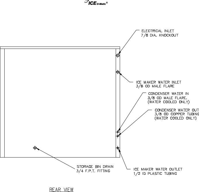
EF Series
Page A7
Flake Ice Machines |
General Information |
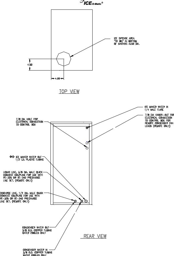
EMF Series
Page A8
Flake Ice Machines |
General Information |
EMF Series (48 Inch Wide)
Page A9
Flake Ice Machines |
General Information |
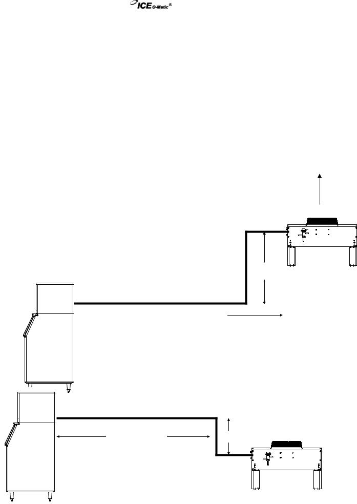
Remote Condenser Installation
The EMF1106R2 and EMF2306R2 remote ice makers incorporate the mixing valve in the condenser. This configuration allows up to a 100 foot calculated remote line set run. Reference the diagram below to calculate the maximum 100 foot line set run.
For proper operation of the ICE-O-Matic ice machine, the following installation guidelines must be followed. Failure to do so may result in loss of production capacity, premature part failure, and may void all warranties.
Remote condensers must be installed per local building codes. A two to four inch diameter roof penetration will be needed for refrigerant lines and electrical conduit. The penetration should be within two feet of where the condenser will be located. A roof jack must be installed at the penetration.
Installation Guidelines
Ambient operating temperatures: -20°F (-28.9°C) to 120°F (48.9°C)
Condenser Airflow: Condensers must have a vertical airflow.
ICE Machine Model Number |
Remote Condenser Model Number |
||
EMF1106R2 |
VRC1061 |
|
|
EMF2306R2 |
VRC2061 |
||
Limitations for new remote machines that have the headmaster mounted in the condenser. |
|||
Maximum Rise is 35 feet. |
|
|
|
Maximum Drop is 15 feet. |
|
|
|
|
|
Airflow |
|
Maximum equivalent run is 100 feet. |
|
|
|
Formula for figuring maximum equivalent run is as follows:
Rise x 1.7 + Drop x 6.6 + horizontal run = equivalent run.
Examples: 35 ft. rise x 1.7 + 40 ft. horizontal = 99.5 equivalent feet line run
35 ft. rise
 40 ft. horizontal
Verify the ICE machine is compatible with the remote condenser. Some ice machines and some remote condensers may or may not have a Mixing Valve (Head Master). Only one valve is required per system. Kits are available to modify the ice machine or condenser for compatibility. For more information contact your
ICE-O-Matic Distributor.
34 ft. horizontal |
10 ft. drop |
|
|
10 ft. drop x 6.6 + 34 ft horizontal = 100 equivalent feet line run
Page A10

Flake Ice Machines |
General Information |
ICE-O-Matic
Parts and Labor
Domestic & International Limited Warranty
Mile High Equipment LLC (the “Company”) warrants ICE-O-Matic brand ice machines, ice dispensers, remote condensers, water filters, and ice storage bins to the end customer against defects in material and factory workmanship for the following:
• Cube ice machines, compressed ice machines and |
• Ice storage bins -Twenty-four (24) month parts and labor |
remote condensers. - Thirty-six (36) months parts and |
|
labor |
|
• Flake ice machines - Twenty-four (24) months parts |
• IOD model dispensers - Twenty-four (24) months parts, Twelve (12) |
and labor |
months labor |
• CD model dispensers - Thirty-six (36) months parts and |
• Water filter systems - Twelve (12) months parts and labor (not including |
labor |
filter cartridges) |
An additional twenty-four (24) month warranty on parts (excluding labor) will be extended to all cube ice machine evaporator plates and all cube ice and compressed ice machine compressors from the date of original installation. An additional thirty-six (36) month warranty on parts (excluding labor) will be extended to all flake ice machine compressors from the date of original installation The company will replace EXW (Incoterms 2000) the Company plant or, EXW (Incoterms 2000) the Company-authorized distributor, without cost to the Customer, that part of any such machine that becomes defective. In the event that the Warranty Registration Card indicating the installation date has not been returned to ICE-O-Matic, the warranty period will begin on the date of shipment from the Company. Irrespective of the actual installation date, the product will be warranted for a maximum of seventy-two (72) months from date of shipment from the Company.
ICE-model cube ice machines which are registered in the Water Filter Extended Warranty Program will receive a total of eighty-four (84) months parts and labor coverage on the evaporator plate from the date of original installation. Water filters must be installed at the time of installation and registered with the Company at that time. Water filter cartridges must be changed every six (6) months and that change reported to the Company to maintain the extended evaporator warranty.
No replacement will be made for any part or assembly which (I) has been subject to an alteration or accident; (II) was used in any way which, in the Company’s opinion, adversely affects the machine’s performance; (III) is from a machine on which the serial number has been altered or removed; or, (IV) uses any replacement part not authorized by the Company. This warranty does not apply to destruction or damage caused by unauthorized service, using other than ICE-O-Matic authorized replacements, risks of transportation, damage resulting from adverse environmental or water conditions, accidents, misuse, abuse, improper drainage, interruption in the electrical or water supply, charges related to the replacement of non-defective parts or components, damage by fire, flood, or acts of God.
This warranty is valid only when installation, service, and preventive maintenance are performed by a Company-authorized distributor, a Company-authorized service agency, or a Company Regional Manager. The Company reserves the right to refuse claims made for ice machines or bins used in more than one location This Limited Warranty does not cover ice bills, normal maintenance, after-install adjustments, and cleaning.
Limitation of Warranty
This warranty is valid only for products produced and shipped from the Company after October 1, 2006. A product produced or installed before that date shall be covered by the Limited Warranty in effect at the date of its shipment. The liability of the Company for breach of this warranty shall, in any case, be limited to the cost of a new part to replace any part, which proves to be defective. The Company makes no representations or warranties of any character as to accessories or auxiliary equipment not manufactured by the Company. REPAIR OR REPLACEMENT AS PROVIDED UNDER THIS WARRANTY IS THE EXCLUSIVE REMEDY OF THE CUSTOMER. MILE HIGH EQUIPMENT SHALL NOT BE LIABLE FOR ANY INCIDENTAL OR CONSEQUENTIAL DAMAGES FOR BREACH OF ANY EXPRESS OR IMPLIED WARRANTY ON THIS PRODUCT. EXCEPT TO THE EXTENT PROHIBITED BY APPLICABLE LAW, ANY IMPLIED WARRANTY OR MERCHANTABILITY OR FITNESS FOR A PARTICULAR PURPOSE ON THIS PRODUCT IS LIMITED IN DURATION TO THE LENGTH OF THIS WARRANTY.
Filing a Claim
All claims for reimbursement must be received at the factory within 90 days from date of service to be eligible for credit. All claims outside this time period will be void. The model, the serial number and, if necessary, proof of installation, must be included in the claim. Claims for labor to replace defective parts must be included with the part claim to receive consideration. Payment on claims for labor will be limited to the published labor time allowance hours in effect at the time of repair. The Company may elect to require the return of components to validate a claim. Any defective part returned must be shipped to the Company or the Company-authorized distributor, transportation charges pre-paid, and properly sealed and tagged. The Company does not assume any responsibility for any expenses incurred in the field incidental to the repair of equipment covered by this warranty. The decision of the Company with respect to repair or replacement of a part shall be final. No person is authorized to give any other warranties or to assume any other liability on the Company’s behalf unless done in writing by an officer of the Company.
GOVERNING LAW
This Limited Warranty shall be governed by the laws of the state of Delaware, U.S.A., excluding their conflicts of law principles. The United Nations Convention on Contracts for the International Sale of Goods is hereby excluded in its entirety from application to this Limited Warranty.
Mile High Equipment LLC, 11100 East 45th Avenue, Denver, Colorado 80239 (303) 371-3737
October 2006
Page A11
Flake Ice Machines |
General Information |
General Operation
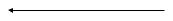
A general description of the flake ice machine operation is given below. The remainder of the manual provides more detail about the components and systems.
Water enters a reservoir through the float valve and is gravity fed into the evaporator barrel through an opening in the bottom of the barrel. Water fills the evaporator to the same level as the water in the reservoir. A float valve, which stops the flow of water into the reservoir when the reservoir becomes full, maintains this water level.
When the ON/OFF switch is turned on or when the bin control closes, the auger motor energizes. The compressor is delayed for 2 to 4 minutes. After the compressor delay period, the condenser fan motor (air cooled machines only) and compressor start and the temperature of the evaporator barrel drops. The water in the evaporator freezes to the inner walls of the evaporator
barrel.
A belt driven gear reducer continuously turns the auger inside the evaporator. As the auger turns, it pushes the ice upward and forces it out of the top of the barrel, through the delivery chute, and into the storage bin. As ice is pushed out through to top of the evaporator, make-up water enters the bottom of the evaporator.
Evaporator
Float
Gear Reducer
V-Belt
Auger Motor
Page A12

Flake Ice Machines |
Scheduled Maintenance |
Danger!
Electrical shock and/or injury from moving parts inside this machine can cause serious injury or death. Disconnect electrical supply to machine prior to performing any adjustments or repair.
Maintenance Procedure
Warning!
Failure to perform the required maintenance at the frequency specified will void warranty coverage in the event of a related failure.
To insure economical, trouble free operation of the ice maker, it is recommended that the following maintenance be performed every 6 months by a qualified service technician.
1.Check the float reservoir for mineral build-up or check the auger drive motor amp draw to determine if the water system needs cleaning. Clean the water system, if necessary, per the instructions on Page B2. Local water conditions may require that cleaning be performed more often than 6 month intervals.
2.Check the water level in the float tank as described on Page D1.
3.Clean the condenser (air cooled machines) to insure unobstructed airflow.
4.Check for leaks of any kind, water, refrigerant, oil, etc.
5.Check the Primary Bin Control for proper adjustment as described on Page G3.
6.Check the Secondary Bin Control for proper adjustment as described on Page G4
7.Check the Safety Control for proper adjustment as described on Page G3.
8.Check the water requlating valve (water cooled machines) for proper adjustment by measuring the water temperature at the outlet of the condenser drain. It should be between 100°F (37.7°C) and 110°F (43.3°C).
9.Check the TXV bulb to make sure that it is securely fastened and properly insulated.
10.Check all electrical connections tightness. Warning: Disconnect electrical supply.
11.Oil the auger motor if the motor has oil fittings.
12.Check the V-Belt for wear and proper tension as described on Page E1.
Page B1

Flake Ice Machines |
Scheduled Maintenance |
CAUTION: Protective eyewear and gloves should be worn when using cleaning products.
CLEANING AND SANITIZING INSTRUCTIONS
1.Turn the machine and water supply to the float off.
2.Remove or melt all ice in the bin.
3.Prepare one gallon (3.75l) of non-chlorine ice machine cleaner i.e. Nu-Calgon Nickel Safe, as directed on container.
4.Turn the machine on, remove the float reservoir cover and add cleaning solution to the reservoir.
5.As the machine makes ice, keep the reservoir filled with the cleaning solution until the entire gallon is used up.
6.Turn the machine off.
7.Prepare 1 gallon (3.75l) of approved (U.S. FDA 21 CFR, 178-1010) food equipment sanitizer to form a solution with 100 – 200 ppm free chlorine yield. Reserve about 1/3 gallon for step #14 below.
8.Turn the machine on and add the sanitizer to the reservoir, keeping the reservoir filled with sanitizer until 2/3 gallon is used up.
9.Turn the machine off.
10.Replace the float reservoir cover and turn the water supply back on.
11.Turn the machine on and allow the machine to make ice for 15 minutes.
12.Turn the machine off and remove and discard all of the ice from the bin made during the cleaning operation.
13.Clean the inside of the bin, bin door, and door frame with warm soapy water and rinse.
14.Using the remainder of the sanitizing solution, wipe all areas of the bin liner, door and door frame, etc. and rinse.
15.Turn machine back on.
Page B2
Flake Ice Machines |
Winterizing Procedures |
Winterizing Procedures
Important!
Whenever the ice machine is taken out of operation during the winter months, the procedure below must be performed. Failure to do so may cause serious damage and will void all warranties.
1.Turn off water to machine.
2.Make sure all ice is out of the evaporator(s)
3.Place the ON/OFF switch to the “OFF” position.
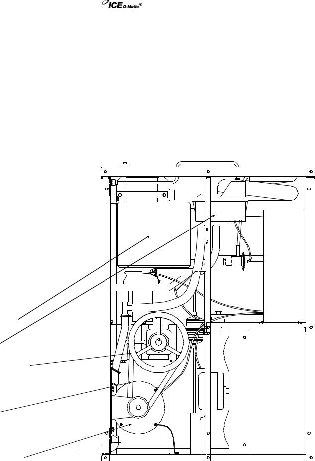
4.Disconnect the tubing between the evaporator and water float.
5.Drain the water system completely.
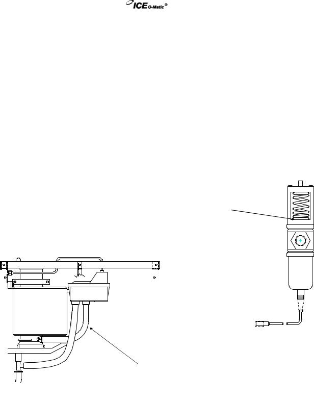
6.On water cooled machines, hold the water regulating valve open by prying upward on the water valve spring with a screwdriver while using compressed air to blow all the water out of the condenser.
7.Remove all of the ice in the storage bin and discard.
Disconnect tubing from float to evaporator and drain water from the evaporator
Page B3

Flake Ice Machines |
Cabinet Care |
Cleaning Stainless Steel
Commercial grades of stainless steel are susceptible to rusting. It is important that you properly care for the stainless steel surfaces of your ice machine and bin to avoid the possibility of rust or corrosion. Use the following recommended guidelines for keeping your stainless steel looking like new:
1.Clean the stainless steel thoroughly once a week. Clean frequently to avoid build-up of hard, stubborn stains. Also, hard water stains left to sit can weaken the steel's corrosion resistance and lead to rust. Use a nonabrasive cloth or sponge, working with, not across, the grain.
2.Don't use abrasive tools to clean the steel surface. Do not use steel wool, abrasive sponge pads, wire brushes or scrapers to clean the steel. Such tools can break through the
"passivation" layer - the thin layer on the surface of stainless steel that protects it from corrosion.
3.Don't use cleaners that use chlorine or chlorides. Don't use chlorine bleach or products like Comet to clean the steel. Chlorides break down the passivation layer and can cause rusting.
4.Rinse with clean water. If chlorinated cleansers are used, you must thoroughly rinse the surface with clean water and wipe dry immediately.
5.Use the right cleaning agent. The table below lists the recommended cleaning agents for common stainless steel cleaning problems:
Cleaning Activity |
Cleaning Agent |
Routine cleaning |
Soap, Ammonia, Windex, or |
|
detergent with water. |
|
Fantastik, 409 Spic’nSpan |
|
Liquid are also approve for |
|
Stainless Steel. |
Removing grease or |
Easy-Off or similar oven |
fatty acids |
cleaners. |
minutes. |
|
Removing hard water spots |
Vinegar |
and scale. |
|
Method of Application
Apply with a clean cloth or sponge. Rinse with clean water and wipe dry.
Apply generously, allow to stand for 15-20
Rinse with clean water. Repeat as required.
Swab or wipe with clean cloth.
Rinse with clean water and dry.
Page B4
Flake Ice Machines |
Troubleshooting Trees |
How To Use The Troubleshooting Trees
The troubleshooting trees were developed to be used in conjunction with the service information in the sections that follow. If used together as intended, these two parts of the manual will allow the ice machine service technician to quickly diagnose many of the problems encountered with the ice machines. When used as designed, the troubleshooting trees can lead you from a general symptom to the most likely component to suspect as the cause of the problem. The trees are not designed to be “parts changer guides”: please do not use them as such.
Components returned to the factory for warranty are tested by the factory and will not be covered under the warranty policy if they are not defective.
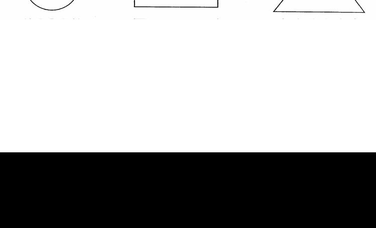
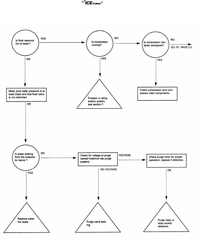
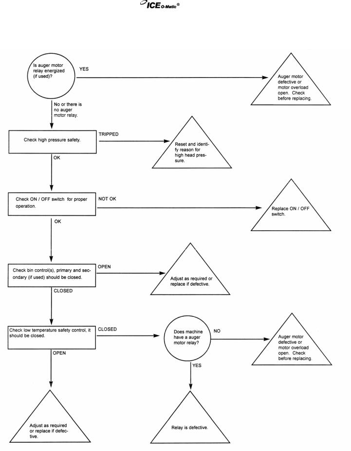
The troubleshooting trees are made of three types of boxes:
QUESTION boxes (Circle) ask a yes/no question and the answer will lead to either another question box, a check box or a solution box.
CHECK boxes (Rectangle) will suggest a point to check for proper operation, and will often refer you to a page in the service information sections of this manual. The result of the check may lead to another box, or a solution box.
SOLUTION boxes (Triangle) suggest the most likely component to cause the malfunction described in the heading of the tree. When reaching a solution box, DO NOT immediately assume the component is defective. The final step is to verify that the component is indeed defective, by using the service information in the sections that follow.
To use the troubleshooting trees, first find the page with the heading describing the type of problem occurring. Begin at the top of the page and follow the tree, step-by-step. When a check box is reached, it may be necessary to refer to another section in the manual.
Once a solution box is reached, refer to the appropriate section to verify that the component in the solution box is, indeed, the problem. Adjust, repair or replace the component as necessary.
Page C1
Flake Ice Machines |
Troubleshooting Trees |
Machine Runs, Does Not Make Ice
Page C2
Flake Ice Machines |
Troubleshooting Trees |
Machine Runs, Does Not Make Ice
Page C3
Flake Ice Machines |
Troubleshooting Trees |
Machine Does Not Run
Page C4
 Loading...