


 Loading...
IBM System x3850 X5 and x3950 X5 |
|
Types 7145, 7146, 7143, and 7191 |
Installation and User's Guide
IBM System x3850 X5 and x3950 X5 |
|
Types 7145, 7146, 7143, and 7191 |
Installation and User's Guide
Note: Before using this information and the product it supports, read the general information in “Notices” on page 121, the
IBM Safety Information and Environmental Notices and User Guide documents on the IBM Documentation CD, and the Warranty Information.
Ninth Edition (July 2011)
© Copyright IBM Corporation 2011.
US Government Users Restricted Rights – Use, duplication or disclosure restricted by GSA ADP Schedule Contract with IBM Corp.

Contents
Safety . . . . . . . . . . . . . |
. |
. |
v |
Chapter 1. The System x3850 X5 and |
|
|
|
x3950 X5 server . . . . . . . . . |
. |
. |
1 |
The IBM Documentation CD . . . . . . . |
. |
|
. 3 |
Hardware and software requirements . . . |
. |
|
. 3 |
Using the Documentation Browser . . . . |
. |
|
. 3 |
Related documentation . . . . . . . . . |
. |
|
. 4 |
Notices and statements in this document . . . . . 5
Features and specifications. . . . . |
. . . |
. |
. |
5 |
What your server offers. . . . . . |
. . . |
. |
. |
8 |
Reliability, availability, and serviceability |
. . . |
. |
|
11 |
IBM Systems Director . . . . . . . |
. . . |
. |
|
12 |
The UpdateXpress System Pack Installer (UXSPI) . . 13 |
||||
Server controls, LEDs, and power . . . |
. . . |
. |
|
13 |
Front view. . . . . . . . . . |
. . . |
. |
|
13 |
Rear view . . . . . . . . . . |
. . . |
. |
|
16 |
Rear view LEDs . . . . . . . . |
. . . |
. |
|
17 |
Server power features . . . . . . |
. . . |
. |
|
19 |
IBM MAX5 for System x memory expansion module 21 Memory expansion module features and specifications . . . . . . . . . . . . . 23
What the memory expansion module offers . |
. |
24 |
Reliability, availability, and serviceability features |
|
|
of the memory expansion module . . . . . |
. |
25 |
LEDs and connectors on the memory expansion module . . . . . . . . . . . . . . . 26 Turning on the memory expansion module . . . 28 Turning off the memory expansion module . . . 28
Chapter 2. Installing optional devices |
|
29 |
Instructions for IBM Business Partners . . . . |
. |
29 |
Server components . . . . . . . . . . . |
. |
30 |
Memory-card DIMM connectors . . . . . |
. 31 |
|
Memory-card LEDs. . . . . . . . . . |
. |
32 |
SAS-backplane connectors . . . . . . . |
. |
33 |
eXFlash backplane connectors . . . . . . |
. |
33 |
Microprocessor-board connectors . . . . . |
. |
34 |
Microprocessor-board LEDs . . . . . . . |
. |
35 |
I/O-board connectors . . . . . . . . . |
. |
36 |
I/O-board jumpers . . . . . . . . . . |
. |
37 |
I/O-board LEDs . . . . . . . . . . . |
. |
38 |
Installation guidelines . . . . . . . . . . |
. |
38 |
A single-power-supply server operating at 208 V |
|
|
ac . . . . . . . . . . . . . . . |
. 39 |
|
System reliability guidelines . . . . . . . |
. |
39 |
Working inside the server with the power on . |
. 40 |
|
Handling static-sensitive devices . . . . . |
. |
40 |
Internal cable routing and connectors. . . . . |
. |
42 |
Removing the top cover . . . . . . . . . |
. |
44 |
Removing the top-cover bracket . . . . . . |
. 44 |
|
Installing the top-cover bracket . . . . . . . |
. |
46 |
Removing the bezel . . . . . . . . . . |
. |
47 |
Installing a PCI Express adapter . . . . . . |
. |
47 |
Installing a ServeRAID adapter for use with eXFlash drives . . . . . . . . . . . . . . . . 49
Installing a hot-swap power supply . . . . |
. |
. 52 |
|
Installing a hot-swap hard disk drive . . . . |
. |
. |
53 |
Installing a DVD (optical) drive . . . . . |
. |
. |
55 |
Installing a 2.5-inch hard disk drive backplane |
. |
. 55 |
|
Installing an eXFlash 1.8-inch drive cage and
backplane . . . . . . . . . . . . . . . 58 Installing a 1.8-inch solid state drive . . . . . . 61 Installing a QPI wrap card . . . . . . . . . 62 Installing an internal removable flash drive. . . . 63
Memory modules . . . . . . . . . . . |
. |
64 |
Installing a memory card . . . . . . . . |
. |
70 |
Installing DIMMs . . . . . . . . . . |
. |
70 |
Installing a microprocessor . . . . . . . . |
. |
73 |
Completing the installation . . . . . . . . |
. |
79 |
Connecting the cables . . . . . . . . . |
. |
79 |
Updating the server configuration . . . . . |
. |
80 |
Installing hardware devices in the memory |
|
|
expansion module . . . . . . . . . . . |
. |
81 |
Memory expansion module components. . . |
. 81 |
|
Removing the memory expansion module bezel |
|
81 |
Removing the memory expansion module |
|
|
system-board tray . . . . . . . . . . |
. |
82 |
Installing DIMMs in the memory expansion
module . . . . . . . . . . . . . . . 83
Installing a memory expansion module hot-swap |
|
|
power supply . . . . . . . . . . . |
. |
88 |
Completing the memory expansion module |
|
|
installation . . . . . . . . . . . . |
. |
90 |
Chapter 3. Configuring the server . . |
. |
95 |
Using the Setup utility. . . . . . . . . . |
. |
96 |
Starting the Setup utility . . . . . . . . |
. |
96 |
Setup utility menu choices . . . . . . . |
. |
96 |
Passwords . . . . . . . . . . . . . 100 |
||
Using the Boot Selection Menu program . . . |
. 102 |
|
Starting the backup UEFI firmware . . . . . |
. 102 |
|
Using the ServerGuide Setup and Installation CD |
|
102 |
ServerGuide features . . . . . . . . . |
. |
103 |
Setup and configuration overview . . . . |
. 103 |
|
Typical operating-system installation . . . |
. |
104 |
Installing your operating system without using ServerGuide . . . . . . . . . . . . . 104
Using the integrated management module. . . . 104
Obtaining the IP address for the IMM web |
|
interface access . . . . . . . . . . . |
. 105 |
Logging on to the IMM web interface . . . |
. 106 |
Using the remote presence and blue-screen capture |
|
features . . . . . . . . . . . . . . |
. 106 |
Using the embedded hypervisor . . . . . . |
. 107 |
Enabling the Broadcom Gigabit Ethernet Utility program . . . . . . . . . . . . . . . 108 Configuring the Broadcom Gigabit Ethernet
controller . . . . . . . . . . . . . . . 108
© Copyright IBM Corp. 2011 |
iii |
Configuring RAID arrays . . . . . . . . |
. |
109 |
Documentation format . . . . . . . . . |
. |
124 |
|
IBM Advanced Settings Utility program . . . |
. |
109 |
Electronic emission notices . . . . . . . . |
. |
124 |
|
Updating IBM Systems Director . . . . . . |
. 109 |
Federal Communications Commission (FCC) |
|
|
||
Configuring an EXA multi-node system . . . |
. |
110 |
statement. . . . . . . . . . . . . |
. |
124 |
|
Creating an EXA multi-node system . . . . |
. 111 |
Industry Canada Class A emission compliance |
|
|
||
Partitioning an EXA multi-node system. . . |
. |
113 |
statement. . . . . . . . . . . . . |
. |
124 |
|
Using the IMM Telnet interface . . . . . |
. 114 |
Avis de conformité à la réglementation |
|
|
||
Configuring a QPI multi-node system . . . . |
. |
116 |
d'Industrie Canada . . . . . . . . . |
. |
124 |
|
|
|
|
Australia and New Zealand Class A statement |
|
125 |
|
Appendix. Getting help and technical |
|
|
European Union EMC Directive conformance |
|
|
|
assistance. . . . . . . . . . . . . |
117 |
statement. . . . . . . . . . . . . |
. |
125 |
||
Before you call . . . . . . . . . . . . |
. |
117 |
Germany Class A statement . . . . . . |
. 125 |
||
Japan VCCI Class A statement. . . . . . |
. 126 |
|||||
Using the documentation . . . . . . . . |
. |
118 |
||||
Japan Electronics and Information Technology |
|
|
||||
Getting help and information from the World Wide |
|
|
|
|||
|
Industries Association (JEITA) statement . . |
. 126 |
||||
Web . . . . . . . . . . . . . . . |
. |
118 |
||||
Korea Communications Commission (KCC) |
|
|
||||
Software service and support . . . . . . . |
. |
118 |
|
|
||
statement. . . . . . . . . . . . . |
. |
127 |
||||
Hardware service and support. . . . . . . |
. |
118 |
||||
Russia Electromagnetic Interference (EMI) Class |
|
|
||||
IBM Taiwan product service . . . . . . . |
. |
119 |
|
|
||
A statement . . . . . . . . . . . . |
. |
127 |
||||
|
|
|
||||
Notices . . . . . . . . . . . . . . 121 |
People's Republic of China Class A electronic |
|
|
|||
emission statement . . . . . . . . . |
. |
127 |
||||
Trademarks . . . . . . . . . . . . . . |
121 |
|||||
Taiwan Class A compliance statement . . . |
. 127 |
|||||
Important notes . . . . . . . . . . . |
. |
122 |
||||
|
|
|
||||
Particulate contamination . . . . . . . . |
. |
123 |
Index . . . . . . . . . . . . . . . 129 |
|||
German Ordinance for Work gloss statement . . . 123 |
||||||
|
|
|
||||
iv IBM System x3850 X5 and x3950 X5 Types 7145, 7146, 7143, and 7191: Installation and User's Guide
Safety
Before installing this product, read the Safety Information.
Antes de instalar este produto, leia as Informações de Segurança.
Læs sikkerhedsforskrifterne, før du installerer dette produkt.
Lees voordat u dit product installeert eerst de veiligheidsvoorschriften.
Ennen kuin asennat tämän tuotteen, lue turvaohjeet kohdasta Safety Information. Avant d'installer ce produit, lisez les consignes de sécurité.
Vor der Installation dieses Produkts die Sicherheitshinweise lesen.
Prima di installare questo prodotto, leggere le Informazioni sulla Sicurezza.
Les sikkerhetsinformasjonen (Safety Information) før du installerer dette produktet.
© Copyright IBM Corp. 2011 |
v |
Antes de instalar este produto, leia as Informações sobre Segurança.
Antes de instalar este producto, lea la información de seguridad.
Läs säkerhetsinformationen innan du installerar den här produkten.
Important:
Each caution and danger statement in this document is labeled with a number. This number is used to cross reference an English-language caution or danger statement with translated versions of the caution or danger statement in the Safety Information document.
For example, if a caution statement is labeled “Statement 1,” translations for that caution statement are in the Safety Information document under “Statement 1.”
Be sure to read all caution and danger statements in this document before you perform the procedures. Read any additional safety information that comes with the server or optional device before you install the device.
Statement 1
vi IBM System x3850 X5 and x3950 X5 Types 7145, 7146, 7143, and 7191: Installation and User's Guide

DANGER
Electrical current from power, telephone, and communication cables is hazardous.
To avoid a shock hazard:
vDo not connect or disconnect any cables or perform installation, maintenance, or reconfiguration of this product during an electrical storm.
vConnect all power cords to a properly wired and grounded electrical outlet.
vConnect to properly wired outlets any equipment that will be attached to this product.
vWhen possible, use one hand only to connect or disconnect signal cables.
vNever turn on any equipment when there is evidence of fire, water, or structural damage.
vDisconnect the attached power cords, telecommunications systems, networks, and modems before you open the device covers, unless instructed otherwise in the installation and configuration procedures.
vConnect and disconnect cables as described in the following table when installing, moving, or opening covers on this product or attached devices.
To Connect:
1.Turn everything OFF.
2.First, attach all cables to devices.
3.Attach signal cables to connectors.
4.Attach power cords to outlet.
5.Turn device ON.
To Disconnect:
1.Turn everything OFF.
2.First, remove power cords from outlet.
3.Remove signal cables from connectors.
4.Remove all cables from devices.
Statement 2
CAUTION:
When replacing the lithium battery, use only IBM Part Number 15F8409 or an equivalent type battery recommended by the manufacturer. If your system has a module containing a lithium battery, replace it only with the same module type made by the same manufacturer. The battery contains lithium and can explode if not properly used, handled, or disposed of.
Do not:
vThrow or immerse into water
vHeat to more than 100°C (212°F)
vRepair or disassemble
Dispose of the battery as required by local ordinances or regulations.
Safety vii
Statement 3
CAUTION:
When laser products (such as CD-ROMs, DVD drives, fiber optic devices, or transmitters) are installed, note the following:
vDo not remove the covers. Removing the covers of the laser product could result in exposure to hazardous laser radiation. There are no serviceable parts inside the device.
vUse of controls or adjustments or performance of procedures other than those specified herein might result in hazardous radiation exposure.
DANGER
Some laser products contain an embedded Class 3A or Class 3B laser diode. Note the following.
Laser radiation when open. Do not stare into the beam, do not view directly with optical instruments, and avoid direct exposure to the beam.
Class 1 Laser Product
Laser Klasse 1
Laser Klass 1
Luokan 1 Laserlaite
`
Appareil A Laser de Classe 1
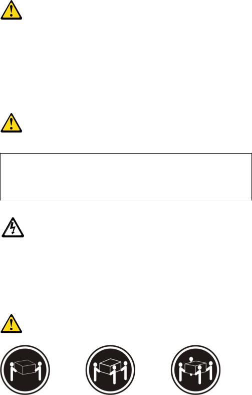
Statement 4
≥ 18 kg (39.7 lb) |
≥ 32 kg (70.5 lb) |
≥ 55 kg (121.2 lb) |
viii IBM System x3850 X5 and x3950 X5 Types 7145, 7146, 7143, and 7191: Installation and User's Guide
CAUTION:
Use safe practices when lifting.
Statement 5
CAUTION:
The power control button on the device and the power switch on the power supply do not turn off the electrical current supplied to the device. The device also might have more than one power cord. To remove all electrical current from the device, ensure that all power cords are disconnected from the power source.
Statement 8
CAUTION:
Never remove the cover on a power supply or any part that has the following label attached.
Hazardous voltage, current, and energy levels are present inside any component that has this label attached. There are no serviceable parts inside these components. If you suspect a problem with one of these parts, contact a service technician.
Statement 11
Safety ix
CAUTION:
The following label indicates sharp edges, corners, or joints nearby.
Statement 12
CAUTION:
The following label indicates a hot surface nearby.
Statement 13
DANGER
Overloading a branch circuit is potentially a fire hazard and a shock hazard under certain conditions. To avoid these hazards, ensure that your system electrical requirements do not exceed branch circuit protection requirements. Refer to the information that is provided with your device for electrical specifications.
Statement 15
CAUTION:
Make sure that the rack is secured properly to avoid tipping when the server unit is extended.
Statement 17
x IBM System x3850 X5 and x3950 X5 Types 7145, 7146, 7143, and 7191: Installation and User's Guide
CAUTION:
The following label indicates moving parts nearby.
Statement 26
CAUTION:
Do not place any object on top of rack-mounted devices.
Statement 37
DANGER
When you populate a rack cabinet, adhere to the following guidelines:
vAlways lower the leveling pads on the rack cabinet.
vAlways install the stabilizer brackets on the rack cabinet.
vAlways install the heaviest devices in the bottom of the rack cabinet.
vDo not extend multiple devices from the rack cabinet simultaneously, unless the rack-mounting instructions direct you to do so. Multiple devices extended into the service position can cause your rack cabinet to tip.
vIf you are not using the IBM 9308 rack cabinet, securely anchor the rack cabinet to ensure its stability.
Attention: This product is suitable for use on an IT power distribution system whose maximum phase-to-phase voltage is 240 V under any distribution fault condition.
Safety xi
xii IBM System x3850 X5 and x3950 X5 Types 7145, 7146, 7143, and 7191: Installation and User's Guide

Chapter 1. The System x3850 X5 and x3950 X5 server
This Installation and User's Guide contains instructions for setting up your IBM System x3850 X5 or x3950 X5 Type 7145, 7146, 7143, or 7191 server, installing optional devices, and starting and configuring the server. This document also contains information and instructions for installing optional devices in the optional IBM MAX5 for System x memory expansion module (see “IBM MAX5 for System x memory expansion module” on page 21 for more information about the optional memory expansion module). For diagnostic and troubleshooting information and instructions for removing and installing server components, see the Problem Determination and Service Guide that is on the IBM Documentation CD.
Important: The IBM MAX5 for System x memory expansion module is an Underwriters Laboratories (UL) Listed Accessory for use with the IBM System x3850 X5 and x3950 X5 servers only.
In addition to the instructions in Chapter 2, “Installing optional devices,” on page 29 for installing optional hardware devices, updating firmware and device drivers, and completing the installation, IBM Business Partners must also complete the steps in “Instructions for IBM Business Partners” on page 29.
The IBM System x3850 X5 and x3950 X5 server is a 4U1-high, high-performance server. It can be upgraded to a symmetric multiprocessing (SMP) server through a microprocessor upgrade. It is ideally suited for networking environments that require superior microprocessor performance, efficient memory management, flexibility, and large amounts of reliable data storage.
Performance, ease of use, reliability, and expansion capabilities were key considerations in the design of the server. These design features make it possible for you to customize the system hardware to meet your needs today and provide flexible expansion capabilities for the future.
For information about features that help increase performance, reliability, and availability, see “What your server offers” on page 8 and “Reliability, availability, and serviceability” on page 11.
The server comes with a limited warranty. For information about the terms of the warranty and getting service and assistance, see the Warranty Information document that comes with the server.
The server contains IBM Enterprise X-Architecture technologies, which help increase performance, reliability, and availability. For more information, see “What your server offers” on page 8 and “Reliability, availability, and serviceability” on page 11.
You can obtain up-to-date information about the server and other IBM® server products at http://www.ibm.com/systems/x/. At http://www.ibm.com/support/ mysupport/, you can create a personalized support page by identifying IBM products that are of interest to you. From this personalized page, you can subscribe
1.Racks are measured in vertical increments of 4.45 cm (1.75 inches) each. Each increment is called a "U." A 1-U-high device is 1.75 inches tall.
© Copyright IBM Corp. 2011 |
1 |
to weekly e-mail notifications about new technical documents, search for information and downloads, and access various administrative services.
If you participate in the IBM client reference program, you can share information about your use of technology, best practices, and innovative solutions; build a professional network; and gain visibility for your business. For more information about the IBM client reference program, see http://www.ibm.com/ibm/ clientreference/.
If firmware and documentation updates are available, you can download them from the IBM website. The server might have features that are not described in the documentation that comes with the server, and the documentation might be updated occasionally to include information about those features, or technical updates might be available to provide additional information that is not included in the server documentation. To check for updates, go to http://www.ibm.com/ supportportal/.
Record information about the server in the following table.
Product name |
IBM System x3850 X5 or x3950 X5 |
Machine type |
7145, 7146, 7143, or 7191 |
Model number |
_____________________________________________ |
Serial number |
_____________________________________________ |
|
|
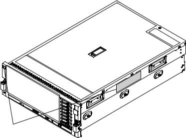
The model number and serial number are on labels on the right side of the server and on the front, visible on the bezel, as shown in the following illustration.
ID labels
For a list of supported optional devices for the server, see http://www.ibm.com/ systems/info/x86servers/serverproven/compat/us/.
2 IBM System x3850 X5 and x3950 X5 Types 7145, 7146, 7143, and 7191: Installation and User's Guide

The IBM Documentation CD
The IBM Documentation CD contains documentation for your server in Portable Document Format (PDF) and includes the IBM Documentation Browser to help you find information quickly.
Hardware and software requirements
The IBM Documentation CD requires the following minimum hardware and software:
vMicrosoft Windows XP, Windows 2000, or Red Hat Linux
v100 MHz microprocessor
v32 MB of RAM
vAdobe Acrobat Reader 3.0 (or later) or xpdf, which comes with Linux operating systems
Using the Documentation Browser
Use the Documentation Browser to browse the contents of the CD, read brief descriptions of the documents, and view documents, using Adobe Acrobat Reader or xpdf. The Documentation Browser automatically detects the regional settings in your server and displays the documents in the language for that region (if available). If a document is not available in the language for that region, the English-language version is displayed.
Use one of the following procedures to start the Documentation Browser:
vIf Autostart is enabled, insert the CD into the CD or DVD drive. The Documentation Browser starts automatically.
vIf Autostart is disabled or is not enabled for all users, use one of the following procedures:
–If you are using a Windows operating system, insert the CD into the CD or DVD drive and click Start --> Run. In the Open field, type
e:\win32.bat
where e is the drive letter of the CD or DVD drive, and click OK.
–If you are using Red Hat Linux, insert the CD into the CD or DVD drive; then, run the following command from the /mnt/cdrom directory:
sh runlinux.sh
Select your server from the Product menu. The Available Topics list displays all the documents for your server. Some documents might be in folders. A plus sign
(+) indicates each folder or document that has additional documents under it. Click the plus sign to display the additional documents.
When you select a document, a description of the document appears under Topic Description. To select more than one document, press and hold the Ctrl key while you select the documents. Click View Book to view the selected document or documents in Acrobat Reader or xpdf. If you selected more than one document, all the selected documents are opened in Acrobat Reader or xpdf.
To search all the documents, type a word or word string in the Search field and click Search. The documents in which the word or word string appears are listed
Chapter 1. The System x3850 X5 and x3950 X5 server 3

in order of the most occurrences. Click a document to view it, and press Ctrl+F to use the Acrobat search function, or press Alt+F to use the xpdf search function within the document.
Click Help for detailed information about using the Documentation Browser.
Related documentation
This Installation and User's Guide contains general information about the server, including how to set up the server, install supported optional devices, and configure the server. The following documentation also comes with the server:
vIBM Warranty Information
This printed document contains the warranty terms and a pointer to the IBM Statement of Limited Warranty on the IBM website.
vSafety Information
This document is in PDF on the IBM Documentation CD. It contains translated caution and danger statements. Each caution and danger statement that appears in the documentation has a number that you can use to locate the corresponding statement in your language in the Safety Information document.
vProblem Determination and Service Guide
This document is in PDF on the IBM Documentation CD. It contains information to help you solve problems yourself, and it contains information for service technicians.
vRack Installation Instructions
This printed document contains detailed instructions for installing your server in a rack.
If you are adding an optional memory expansion module or scaling to another server, see the rack installation instructions that comes with the cable option kit.
vEnvironmental Notices and User's Guide
This document is in PDF on the IBM Documentation CD. It contains translated environmental notices.
vIBM License Agreement for Machine Code
This document is in PDF on the IBM Documentation CD. It provides translated versions of the IBM License Agreement for Machine Code for your product.
vLicenses and Attributions Document
This document is in PDF on the IBM Documentation CD. It provides the open-source notices.
Depending on the server model, additional documentation might be included on the IBM Documentation CD.
The ToolsCenter for System x and BladeCenter is an online information center that contains information about tools for updating, managing, and deploying firmware, device drivers, and operating systems. The ToolsCenter for System x and BladeCenter is at http://publib.boulder.ibm.com/infocenter/toolsctr/v1r0/ index.jsp.
The server might have features that are not described in the documentation that comes with the server. The documentation might be updated occasionally to include information about those features, or technical updates might be available
4 IBM System x3850 X5 and x3950 X5 Types 7145, 7146, 7143, and 7191: Installation and User's Guide

to provide additional information that is not included in the server documentation. To check for updated documentation and technical updates, go to http://www.ibm.com/supportportal/.
Notices and statements in this document
The caution and danger statements in this document are also in the multilingual Safety Information document, which is on the IBM Documentation CD. Each statement is numbered for reference to the corresponding statement in your language in the Safety Information document.
The following notices and statements are used in this document:
vNote: These notices provide important tips, guidance, or advice.
vImportant: These notices provide information or advice that might help you avoid inconvenient or problem situations.
vAttention: These notices indicate potential damage to programs, devices, or data. An attention notice is placed just before the instruction or situation in which damage might occur.
vCaution: These statements indicate situations that can be potentially hazardous to you. A caution statement is placed just before the description of a potentially hazardous procedure step or situation.
vDanger: These statements indicate situations that can be potentially lethal or extremely hazardous to you. A danger statement is placed just before the description of a potentially lethal or extremely hazardous procedure step or situation.
Features and specifications
The following information is a summary of the features and specifications of the server. Depending on the server model, some features might not be available, or some specifications might not apply.
Notes:
1.Racks are marked in vertical increments of 4.45 cm (1.75 inches). Each increment is referred to as a unit, or “U.” A 1-U-high device is 4.45 cm (1.75 inches) tall.
2.Power consumption and heat output vary depending on the number and type of optional features that are installed and the power-management optional features that are in use.
3.The sound levels were measured in controlled acoustical environments according to the procedures specified by the American National Standards Institute (ANSI) S12.10 and ISO 7779 and are reported in accordance with ISO 9296. Actual sound-pressure levels in a given location might exceed the average values stated because of room reflections and other nearby noise sources. The declared sound-power levels indicate an upper limit, below which a large number of computers will operate.
4.When you add an optional memory expansion module to your server configuration and you plan to use the optional USB flash device with VMware ESXi embedded hypervisor software, see the documentation that comes with the USB flash device and the operating system installation instructions for installing ESXi (or ESX, depending on your environment) on your server at
Chapter 1. The System x3850 X5 and x3950 X5 server 5
http://www.ibm.com/supportportal/. The documentation provides additional installation and configuration information that you must follow before you use the memory expansion module.
6 IBM System x3850 X5 and x3950 X5 Types 7145, 7146, 7143, and 7191: Installation and User's Guide
Table 1. Features and specifications
Microprocessor:
vIntel Xeon EX versions of the 6000 and 7000 Series or E7 Series multi-core microprocessor with up to 24 MB or 30 MB last level cache.
v1066 MHz front-side bus (FSB)
vSupport for up to four microprocessors
–Four Quick Path Interconnect (QPI) links per microprocessor at up to 6.4 GT/s (gigatransfers per second)
–Four Scalable Memory Interconnect (SMI) links per microprocessor at up to 6.4 GT/s
Note: Use the Setup utility to determine the type and speed of the microprocessors. The server does not support mixing microprocessor types.
Memory:
vType: Registered, ECC, PC3-10600 double data rate (DDR) III, SDRAM
vSizes: 1 GB (Types 7145 and 7146 only) and 2 GB (PC3-10600 running at 1066 Mb/sec), 4 GB, 8 GB, 16 GB, and 32 GB (Types 7143 and 7191 only) (PC3L-8500-777 DDR3 ECC running at 1066 Mb/sec) in pairs
vMinimum (Types 7145 and 7146): 2 GB (two DIMMs per memory card minimum)
vMinimum (Types 7143 and 7191): 4 GB (two DIMMs per memory card minimum)
vMaximum: 1 TB (2 TB when using 32 GB DIMMs in Types 7143 and 7191) (eight memory cards, each card containing 8 DIMM connectors for a total of 64 DIMMs)
vConnectors: Two-way interleaved, eight dual inline memory module (DIMM) connectors per memory card
vSupports 1.35-volt (low-voltage) and 1.5-volt registered DIMMs
vMachine Types 7145 and 7146 uses the Intel 7500 Scalable Memory Buffer only
vMachine Types 7143 and 7191 uses the Intel 7510 Scalable Memory Buffer only
Expansion slots:
vSix non-hot-swap PCI Express x8 (three full-length and three half-length) slots (slot 2 is electrically x4)
vOne non-hot-swap PCI Express x16 (full-length) slot
vEmulex 10 GbE Custom Adapter for IBM System x in slot 7 (optional in some models)
Upgradeable microcode:
System UEFI, FPGA, diagnostics, service processor, IMM, and SAS microcode
Power supply:
vStandard: One or two dual-rated power supplies (depending on the model).
–1975 watts at 220 V ac input
–875 watts at 110 V ac input
vHot-swappable and redundant at 220 V ac, only with two power supplies
vIf the server is operating at 110 V ac, a second power supply must be installed.
Size:
v4U
vHeight: 172.8 mm (6.81 in.)
vDepth: 712.13 mm (28.04 in.)
vWidth: (without rack EIA brackets) 440 mm (17.32 in.)
vWidth: (with rack EIA brackets) 482.6 mm (19 in.)
vWeight: approximately 49.90 kg (110 lb) when fully configured
Drives:
vSlim CD/DVD-ROM: SATA (optional)
vSerial Attached SCSI (SAS) 2.5-inch hard disk drives (optional)
vSolid state 1.8-inch drives (optional)
Expansion bays:
vEight SAS, 2.5-inch bays or sixteen solid state 1.8-inch bays
vOne 12.7 mm removable-media drive bay (CD/DVD drive optional)
Acoustical noise emissions:
vSound power, idle: 5.8 bel declared
vSound power, operating: 6.3 bel declared
Airflow:
vNominal airflow: 67 cubic feet per minute (CFM)
vTypical airflow: 100 CFM
vMaximum airflow: 241 CFM
Environment:
vAir temperature:
–Server on:
-10°C to 35°C (50°F to 95°F); altitude: 0 to 914 m (3000 ft).
-10°C to 32°C (50°F to 90°F); altitude: 914 to 2133 m (7000 ft).
–Server off: 10°C to 43°C (50.0°F to 109.4°F); maximum altitude: 2133 m (6998.0 ft)
vHumidity:
–Server on: 8% to 80%
–Server off: 8% to 80%
vParticulate contamination:
Attention: Airborne particulates and reactive gases acting alone or in combination with other environmental factors such as humidity or temperature might pose a risk to the server. For information about the limits for particulates and gases, see “Particulate contamination” on page 123.
Heat output:
Approximate heat output:
vMinimum configuration: 648 Btu per hour (190 watts)
vTypical configuration: 3753 Btu per hour (1100 watts)
vDesign maximum configuration:
–5971 Btu per hour (1930 watts) at
110 V ac
–6739 Btu per hour (2150 watts) at
220 V ac
Chapter 1. The System x3850 X5 and x3950 X5 server 7

Table 2. Features and specifications (continued)
Scalability and memory expansion: |
Integrated functions: |
Electrical input: |
||
v Eight-socket scalability option uses |
v |
Integrated management module |
v Sine-wave input (50 - 60 Hz) |
|
4 QPI external cables |
|
(IMM), which provides service |
required |
|
v Multi-node configurations require 4 |
|
processor control and monitoring |
v Input voltage low range: |
|
microprocessors in each node |
|
functions, video controller, and |
– Minimum: 100 V ac |
|
v MAX5 memory expansion module |
|
remote keyboard, video, mouse, |
– |
Maximum: 127 V ac |
option uses four QPI ports |
|
and remote hard disk drive |
v Input voltage high range: |
|
Note: When you add an optional |
v |
capabilities |
– Minimum: 200 V ac |
|
memory expansion module to your |
Light path diagnostics |
– |
Maximum: 240 V ac |
|
server configuration and you plan |
v |
Eight Universal Serial Bus (USB) |
v Approximate input kilovolt-amperes |
|
to use the optional USB flash |
|
ports (2.0) |
(kVA): |
|
device with VMware EXSi |
|
– Four on rear of server |
– |
Minimum: 0.20 kVA |
embedded hypervisor software, see |
|
– Two on front of server |
– |
Typical: 1.12 kVA |
the documentation that comes with |
v |
– Two internal |
– Maximum: 1.95 kVA (110 V ac) |
|
the USB flash device and the |
Broadcom 5709 dual 10/100/1000 |
– Maximum: 2.17 kVA (220 V ac) |
||
operation system installation |
v |
MB Ethernet controller |
|
|
instructions for installing VMware |
Matrox video |
|
|
|
ESXi (or ESX, depending on your |
|
– 16 MB video memory |
|
|
enviroment) on your server at the |
v |
– SVGA compatible |
|
|
IBM websight at |
Serial-attached SCSI (SAS) |
|
|
|
http://www.ibm.com/systems/ |
v |
controller with RAID capabilities |
|
|
support/. The documentation |
Support for ServeRAID-BR10i |
|
|
|
provides additional installation and |
|
SAS/SATA controllers (Types 7145 |
|
|
configuration information that you |
|
and 7146 only) or |
|
|
need to follow before you use the |
|
ServeRAID-M1015 SAS/SATA |
|
|
memory expansion module. |
|
controllers (Types 7143 and 7191 |
|
|
|
|
only) and ServeRAID-M5015 |
|
|
|
|
SAS/SATA/SSD controllers (all |
|
|
|
v |
Types) |
|
|
|
Serial connector |
|
|
|
|
v |
QPI Expansion Ports |
|
|
What your server offers
The server uses the following features and technologies:
vUEFI-compliant server firmware
IBM UEFI firmware offers several features, including Unified Extensible Firmware Interface (UEFI) 2.1 compliance; Active Energy Manager technology; enhanced reliability, availability, and serviceability (RAS) capabilities; and basic input/output system (BIOS) compatibility support. UEFI replaces the BIOS and
defines a standard interface between the operating system, platform firmware, and external devices. UEFI-compliant System x® servers are capable of booting UEFI-compliant operating systems, BIOS-based operating systems, and BIOS-based adapters as well as UEFI-compliant adapters.
Note: The server does not support DOS.
For more information about UEFI, go to http://www-947.ibm.com/systems/ support/supportsite.wss/docdisplay?lndocid=MIGR-5083207 &brandind=5000008.
vIntegrated management module
The integrated management module (IMM) combines service processor functions, video controller, and remote presence and blue-screen capture features in a single chip. The IMM provides advanced service processor control, monitoring, and alerting function. If an environmental condition exceeds a
8 IBM System x3850 X5 and x3950 X5 Types 7145, 7146, 7143, and 7191: Installation and User's Guide
threshold or if a system component fails, the IMM lights LEDs to help you diagnose the problem, records the error in the IMM event log, and alerts you to the problem. Optionally, the IMM also provides a virtual presence capability for remote server management capabilities. The IMM provides remote server management through industry-standard interfaces:
–Intelligent Platform Management Interface (IPMI) version 2.0
–Simple Network Management Protocol (SNMP) version 3
–Common Information Model (CIM)
–Web browser (For more information, see “Using the integrated management module” on page 104.)
v IBM Systems Director
IBM Systems Director is a platform-management foundation that streamlines the way you manage physical and virtual systems in a heterogeneous environment. By using industry standards, IBM Systems Director supports multiple operating systems and virtualization technologies for IBM and non-IBM x86 platforms. For more information, see the documentation on the IBM Systems Director DVD and “IBM Systems Director” on page 12.
vIBM Electronic Service Agent
IBM Electronic Service Agent is a software tool that monitors the server for hardware error events and automatically submits electronic service requests to IBM service and support. Also, it can collect and transmit system configuration information on a scheduled basis so that the information is available to you and your support representative. It uses minimal system resources, is available free of charge, and can be downloaded from the web. For more information and to download Electronic Service Agent, go to http://www.ibm.com/support/ electronic/.
vIBM X-Architecture® technology
IBM X-Architecture technology combines proven, innovative IBM designs to make your x86-processor-based server powerful, scalable, and reliable. For more information, see http://www.ibm.com/servers/eserver/xseries/xarchitecture/ enterprise/index.html.
vLarge system-memory capacity
The server supports up to 1 TB of system memory. The memory controller supports error correcting code (ECC) for up to 64 industry-standard PC3-10600, 240-pin, registered, double-data-rate (DDR) III, synchronous dynamic random access memory (SDRAM) dual inline memory modules (DIMMs). The optional 32-DIMM IBM MAX5 for System x memory expansion module is available for purchase and provides up to 512 GB of additional memory. For more information about the memory expansion module, see “IBM MAX5 for System x memory expansion module” on page 21.
vMemory ProteXion
The Memory ProteXion feature provides the equivalent of a hot-spare drive in a RAID array. It is based in the memory controller, and it enables the server to sense when a chip on a DIMM has failed and to route the data around the failed chip.
vMemory Sparing
The server supports memory sparing. Memory sparing reserves memory capacity for failover in the event of a DIMM failure, and the reserved capacity is subtracted from the total available memory. Memory sparing provides less redundancy than memory mirroring does. If a predetermined threshold of correctable errors is reached, the contents of the failing DIMM are copied to the spare memory, and the failing DIMM or rank is disabled. To enable memory
Chapter 1. The System x3850 X5 and x3950 X5 server 9
sparing through the Setup utility, select System Settings > Memory. (Memory sparing and memory mirroring cannot be used together.)
vIBM ServerGuide Setup and Installation CD
The ServerGuide Setup and Installation CD, which you can download from the web, provides programs to help you set up the server and install a Windows operating system. The ServerGuide program detects installed optional hardware devices and provides the correct configuration programs and device drivers. For more information about the ServerGuide Setup and Installation CD, see “Using the ServerGuide Setup and Installation CD” on page 102.
vIntegrated network support
The server comes with an integrated Broadcom 5709 dual Gigabit Ethernet controller, which supports connection to a 10 Mbps, 100 Mbps, or 1000 Mbps network. For more information, see “Configuring the Broadcom Gigabit Ethernet controller” on page 108.
vIntegrated Trusted Platform Module (TPM)
This integrated security chip performs cryptographic functions and stores private and public secure keys. It provides the hardware support for the Trusted Computing Group (TCG) specification. You can download the software to support the TCG specification, when the software is available.
vLarge data-storage capacity and hot-swap capability
The server supports up to eight 1-inch (26 mm) slim-high, 2.5-inch hot-swap hard disk drives that are connected to two SAS backplanes. With the hot-swap feature, you can add, remove, and replace hard disk drives without turning off the server. For more information, see “Installing a hot-swap power supply” on page 52.
vLight path diagnostics
Light path diagnostics provides LEDs to help you diagnose problems. For more information, see the section about light path diagnostics in the Problem Determination and Service Guide.
vPCI Express 2.0 adapter capabilities
The server has six slots for PCI Express 2.0 x8 adapters and one slot for PCI Express x16 adapters. For more information, see “Installing a PCI Express adapter” on page 47.
vActive Energy Manager
The Active Energy Manager solution is an IBM Systems Director extension that measures and reports server power consumption as it occurs. This enables you to monitor power consumption in correlation to specific software applications programs and hardware configurations. You can obtain the measurement values through the systems-management interface and view them, using IBM Systems Director. For more information, see the documentation on the IBM Systems Director DVD, or see http://www.ibm.com/systems/management/director/ extensions/actengmgr.html.
vDynamic System Analysis (DSA) Preboot diagnostic programs
The DSA Preboot diagnostic programs are stored in integrated USB memory and collect and analyze system information to aid in diagnosing server problems. The diagnostic programs collect the following information about the server:
–Event logs for ServeRAID controllers and service processors
–Hard disk drive health
–Installed hardware
–Light path diagnostics status
–Network interfaces and settings
–RAID controller configuration
10 IBM System x3850 X5 and x3950 X5 Types 7145, 7146, 7143, and 7191: Installation and User's Guide

–Service processor status and configuration
–System configuration
–Vital product data, firmware, and UEFI configuration
For additional information about DSA, see the Problem Determination and Service Guide on the IBM Documentation CD.
vRedundant connection
The addition of an optional network interface card (NIC) provides a failover capability to a redundant Ethernet connection. If a problem occurs with the primary Ethernet connection, all Ethernet traffic that is associated with the primary connection is automatically switched to the redundant NIC. If the applicable device drivers are installed, this switching occurs without data loss and without user intervention.
vRedundant cooling and power capabilities
The redundant cooling of the fans in the server enables continued operation if one of the fans fails. The server supports up to two hot-swap power supplies, which provide redundant power for many server configurations.
vServeRAID support
The server supports ServeRAID controllers to create a redundant array of independent disks (RAID) configurations.
vSymmetric multiprocessing (SMP)
The server supports up to four multi-core Intel Xeon microprocessors. One or more multi-core microprocessors provides SMP capability.
Reliability, availability, and serviceability
Three important server design features are reliability, availability, and serviceability (RAS). The RAS features help to ensure the integrity of the data that is stored in the server, the availability of the server when you need it, and the ease with which you can diagnose and correct problems.
The server has the following RAS features:
vAdvanced memory features:
–Single-bit memory error detection
–Single-bit memory error hardware correction
–Multi single-bit memory error recovery and corrections
–Uncorrectable error (UE) detection
–Full array memory mirroring (FAMM) redundancy
–Automatic failover recovery for UEs when FAMM is configured
–Automated logical removal of failed DIMMs on reboots prior to replacement
–Automatic address parity checking during writes and reads
vAutomatic BIOS recovery (ABR) for UEFI
vAutomatic error retry and recovery
vAutomatic restart after a power failure
vAvailability of microcode and diagnostic levels
vIntegrated management module (service processor)
vBuilt-in, menu-driven electrically erasable programmable ROM (EEPROM) based setup, system configuration, and diagnostic programs
vBuilt-in monitoring for fan, power, temperature, voltage, and power-supply redundancy
vError codes and messages
vError correcting code (ECC) L2 cache and system memory
vFault-resistant startup
vHot-swap hard disk drives
Chapter 1. The System x3850 X5 and x3950 X5 server 11

vIBM Systems Director workgroup-hardware-management tool
vInformation and light path diagnostics LED panels
vIntegrated management module
vService processor adapter for remote systems management
vParity checking on the SAS bus and PCI Express buses
vPower managed and Advanced Configuration and Power Interface (ACPI) compliant
vPower-on self-test (POST)
vPredictive Failure Analysis (PFA) alerts
vRedundant Ethernet capabilities (requires optional Ethernet adapter) with failover support
vRedundant hot-swap capability
–Cooling fans with speed-sensing capability
–Power supplies
vRemind button to temporarily flash the system-error LED
vRemote system problem-determination support
vROM-based diagnostic programs
vStandby voltage for systems-management features and monitoring
vStartup (boot) from LAN using Preboot Execution Environment (PXE) protocol
vSystem auto-configuring from the configuration menu
vSystem error logging
vUpgradeable microcode for POST, IMM, diagnostics, service processor, and read-only memory (ROM) resident code, locally or over the LAN
vVital product data (VPD) on microprocessors, system boards, power supplies, and SAS (hot-swap-drive) backplane
vWake on LAN capability
IBM Systems Director
IBM Systems Director is a platform-management foundation that streamlines the way you manage physical and virtual systems in a heterogeneous environment. By using industry standards, IBM Systems Director supports multiple operating systems and virtualization technologies in IBM and non-IBM x86 platforms.
Through a single user interface, IBM Systems Director provides consistent views for viewing managed systems, determining how these systems relate to one another, and identifying their statuses, helping to correlate technical resources with business needs. A set of common tasks that are included with IBM Systems Director provides many of the core capabilities that are required for basic management, which means instant out-of-the-box business value. These common tasks include discovery, inventory, configuration, system health, monitoring, updates, event notification, and automation for managed systems.
The IBM Systems Director Web and command-line interfaces provide a consistent interface that is focused on driving these common tasks and capabilities:
vDiscovering, navigating, and visualizing systems on the network with the detailed inventory and relationships to the other network resources
vNotifying users of problems that occur on systems and the ability to isolate the sources of the problems
vNotifying users when systems need updates and distributing and installing updates on a schedule
vAnalyzing real-time data for systems and setting critical thresholds that notify the administrator of emerging problems
12 IBM System x3850 X5 and x3950 X5 Types 7145, 7146, 7143, and 7191: Installation and User's Guide
vConfiguring settings of a single system and creating a configuration plan that can apply those setting to multiple systems
vUpdating installed plug-ins to add new features and functions to the base capabilities
vManaging the life cycles of virtual resources
For more information about IBM Systems Director, see the documentation on the IBM Systems Director DVD that comes with the server, the IBM Systems Director Information Center at http://publib.boulder.ibm.com/infocenter/director/v6r1x/ index.jsp?topic=/director_6.1/fqm0_main.html and the Systems Management Web page at http://www.ibm.com/systems/management/, which presents an overview of IBM Systems Management and IBM Systems Director.
The UpdateXpress System Pack Installer (UXSPI)
The UpdateXpress System Pack Installer detects supported and installed device drivers and firmware in the server and installs available updates. For additional information and to download the UpdateXpress System Pack Installer, go to the ToolsCenter for System x and BladeCenter at http://publib.boulder.ibm.com/ infocenter/toolsctr/v1r0/index.jsp and click UpdateXpress System Pack Installer.
Server controls, LEDs, and power
This section describes the controls, light-emitting diodes (LEDs), connectors on the front and rear of the server, and how to turn the server on and off.
Note: The illustrations in this document might differ slightly from your server.
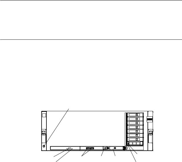
Front view
The following illustration shows the controls, LEDs, and connectors on the front of the server. (See “Operator information panel” on page 14 for information about the operator information panel.) The DVD drive is optional in some models.
Electrostatic-discharge connector
DVD-eject |
USB connectors Scalability |
Operator |
Hard disk drive |
status LED |
|||
button |
LED |
information |
Hard disk drive |
DVD drive |
|
panel |
|
|
activity LED |
||
activity LED |
|
|
|
|
|
|
Electrostatic-discharge connector: Connect a electrostatic-discharge wrist strap to this connector when you work with static-sensitive devices.
DVD-eject button: Press this button to release a CD or DVD from the DVD drive.
Chapter 1. The System x3850 X5 and x3950 X5 server 13
DVD drive activity LED: When this LED is lit, it indicates that the DVD drive is in use.
USB 1 and 2 connectors: Connect USB devices to these connectors.
Scalability LED: This white LED is lit when the server is connected to another server in a multi-node configuration. This LED is lit and remains on after POST on the primary and secondary server.
Hard disk drive activity LED: When this LED is flashing, it indicates that the drive is in use.
Hard disk drive status LED: On some server models, each hot-swap hard disk drive has a status LED. When this LED is lit, it indicates that the drive has failed. If an optional IBM ServeRAID controller is installed in the server, when this LED is flashing slowly (one flash per second), it indicates that the drive is being rebuilt. When the LED is flashing rapidly (three flashes per second), it indicates that the controller is identifying the drive.
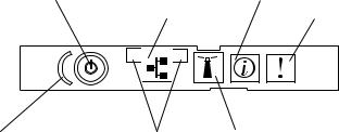
Operator information panel
The following illustration shows the controls and LEDs on the operator information panel.
Power-control button/power-on LED |
Information LED |
Ethernet icon LED |
System-error LED |
1 


 2
2
Power-control button cover Ethernet port activity LEDs |
Locator button/locator LED |
The following controls and LEDs are on the operator information panel:
vPower-control button and power-on LED: Press this button to turn the server on and off manually or to wake the server from a reduced-power state. The states of the power-on LED are as follows:
Off: AC power is not present, or the power supply or the LED itself has failed.
Flashing rapidly (4 times per second): The server is turned off and is not ready to be turned on. The power-control button is disabled. In a fully configured server, it could take up to 8 minutes after the server is connected to ac power, before the power-control button becomes active.
Flashing slowly (once per second): The server is turned off and is ready to be turned on. You can press the power-control button to turn on the server.
Lit: The server is turned on.
Fading on and off: The server is in a reduced-power state. To wake the server, press the power-control button or use the IMM web interface. For information about logging on to the IMM web interface, see “Logging on to the IMM web interface” on page 106.
v Ethernet icon LED: This LED lights the Ethernet icon.
14 IBM System x3850 X5 and x3950 X5 Types 7145, 7146, 7143, and 7191: Installation and User's Guide
vInformation LED: When this LED is lit, it indicates that a noncritical event has occurred. An LED on the light path diagnostics panel is also lit to help isolate the error.
vSystem-error LED: When this LED is lit, it indicates that a system error has occurred. An LED on the light path diagnostics panel is also lit to help isolate the error.
vLocator button and locator LED: Use this LED to visually locate the server among other servers. It is also used as the physical presence for trusted Platform Module (TPM). Press this button to turn on or turn off this LED locally. You can use IBM Systems Director to light this LED remotely.
In a two-node configuration, this LED is lit on the primary server and flashes on the secondary server during POST.
You can press this button or use an IPMI command to turn this LED on or off.
vEthernet port activity LEDs: When either of these LEDs is lit, it indicates that the server is transmitting to or receiving signals from the Ethernet LAN that is connected to the Ethernet port that corresponds to that LED.
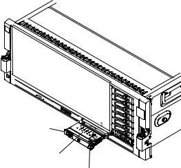
Light path diagnostics panel
The light path diagnostics panel is on the top of the operator information panel.
To access the light path diagnostics panel, slide the blue release button on the operator information panel to the left. Pull forward on the operator information panel until the hinge of the panel is free of the server chassis. Then pull down on the operator information panel, so that you can view the light path diagnostics panel information.
Operator information panel
Light path diagnostics LEDs
Release latch
The following illustration shows the controls and LEDs on the light path diagnostics panel.
Note:
1.Do not run the server for an extended period of time while the light path diagnostics panel is pulled out of the server.
2.Light path diagnostics LEDs remain lit only while the server is connected to power.
Chapter 1. The System x3850 X5 and x3950 X5 server 15

REMIND |
Remind |
OVER SPEC LOG LINK PS PCI SP |
button |
|
FAN TEMP MEM NMI
NMI button
CNFG CPU VRM DASD RAID BRD
Check point code display
Light Path Diagnostics
Reset button
vRemind button: This button places the system-error LED on the front panel into Remind mode. In Remind mode, the system-error LED flashes once every 2 seconds until the problem is corrected, the server is restarted, or a new problem occurs.
By placing the system-error LED indicator in Remind mode, you acknowledge that you are aware of the last failure but will not take immediate action to correct the problem. The remind function is controlled by the IMM.
vNMI button: Press this button to force a nonmaskable interrupt to the microprocessor, if you are directed to do so by IBM service.
vReset button: Press this button to reset the server and run the power-on self-test (POST). You might have to use a pen or the end of a straightened paper clip to press the button. The reset button is in the lower-right corner of the light path diagnostics panel.
For more information about light path diagnostics, see the Problem Determination and Service Guide on the IBM Documentation CD.
Rear view
The following illustration shows the connectors on the rear of the server.
Power-cord connector: Connect the power cord to this connector.
16 IBM System x3850 X5 and x3950 X5 Types 7145, 7146, 7143, and 7191: Installation and User's Guide
Loading...