


 Loading...
2005
HUV4420 and HUV4420-D Illustrated Parts List
HUV4420 and HUV4420-D
Gasoline and Diesel Vehicles
Manual Number 603001805
Edition Code 0105F1207E

USING THE ILLUSTRATED PARTS LIST
ýWARNING
•This manual is to be used only for identification and ordering of service parts. Be sure to read and use the maintenance and service manual before attempting any vehicle repairs.
This manual covers all HUV4420 gasoline and HUV4420-D diesel vehicles.
The manual is divided into 15 sections. Sections 1 through 14 pertain to the gasoline and diesel vehicles, Section 15 pertains to tools that are used on all Husqvarna products.
Use the Table of Contents to find the sections and pages that contain the parts and assemblies you seek. The Table of Contents lists section numbers, and under them, the individual page titles and numbers to be found in that section. The index can be used to find specific parts and assemblies. The index is divided into numerical and alphabetical listings with the page numbers in italic text.
There is a two-page spread for each individual page title in the Table of Contents. On the left-hand page is an illustration showing the parts in their relative positions; the parts are each tagged with an item number in a balloon. The right-hand page is the parts list page, and gives the page title at the top, then the item numbers (corresponding to the numbers on the illustration), part descriptions, and quantity of parts used.
Note that a part description may be indented. This indention corresponds to a parts assembly level indicated by the numbers 1, 2, 3, and 4 at the top left corner of the parts description area of the parts list page. A part that is indented to level 2 is a component of the level 1 part (assembly) that it is listed under. A level 3 part is a component of the level 2 part that it is listed under, and a level 4 part is a component of the level 3 part preceding it. In each case, the part quantity given for a level 2, 3, or 4 part is the quantity used per next higher level assembly of which it is a component. A part that is not indented is a level 1 part. This means that the quantity given is the quantity used per the portion of the vehicle illustrated on that particular spread.
HOW TO ORDER PARTS
Replacement parts and accessories can be obtained from our network of authorized dealers and distributors. For the name and address of the Husqvarna representative nearest you, logon to our web site at www.usa.husqvarna.com. If you would prefer to write to us, direct your letter to: Husqvarna, Attention: Marketing Services, 7349 Statesville Rd., Charlotte, NC 28269 USA. Your local authorized Husqvarna representative can also provide technical advice, parts, and service manuals.
Husqvarna Forest and Garden
7349 Statesville Rd.
Charlotte, NC 28269
USA www.husqvarna.com
NOTE: This illustrated parts list represents the most current information at the time of publication. Husqvarna is continually working to further improve its vehicles and other products. These improvements may affect the parts used to service the vehicle. Any modification and/or significant change in specifications will be forwarded to all Husqvarna distributors/dealers and will, when applicable, appear in future editions of this illustrated parts list.
Husqvarna reserves the right to change specifications and designs at any time without notice and without the obligation of making changes to units previously sold.
2005 HUV4420 and HUV4420-D Gasoline and Diesel Vehicles Illustrated Parts List

|
CONTENTS |
|
|
SECTION 1 – BODY AND TRIM |
|
|
|
Front Body Trim, Gasoline Vehicles ................................................................................................. |
1-3 |
Front Body Trim, Diesel Vehicles ..................................................................................................... |
1-5 |
Front Body Components ................................................................................................................... |
1-7 |
Front Seats and Cup Holder ............................................................................................................. |
1-9 |
ROPS ................................................................................................................................................ |
1-11 |
Tilt Bed and Hinge ............................................................................................................................ |
1-13 |
Electric Bed Lift ................................................................................................................................. |
1-15 |
Cargo Box ......................................................................................................................................... |
1-17 |
Rear Body Trim ................................................................................................................................. |
1-19 |
Camouflage Covers .......................................................................................................................... |
1-21 |
SECTION 2 – WHEELS AND TIRES |
|
|
|
Wheels and Tires, All-Terrain Tread ................................................................................................. |
2-3 |
Wheels and Tires, Mud Tread .......................................................................................................... |
2-5 |
SECTION 3 – DECALS |
|
|
|
Safety Decals, Gasoline Decals ....................................................................................................... |
3-3 |
Safety Decals, Gasoline Vehicles, Continued .................................................................................. |
3-5 |
Safety Decals, Diesel Vehicles ......................................................................................................... |
3-7 |
Safety Decals, Diesel Vehicles, Continued ....................................................................................... |
3-9 |
Badging Decals, HUV 4420 .............................................................................................................. |
3-11 |
SECTION 4 – BRAKE SYSTEMS |
|
|
|
Front Brake Assembly ...................................................................................................................... |
4-3 |
Rear Brake Assembly ....................................................................................................................... |
4-5 |
Master Cylinder ................................................................................................................................. |
4-7 |
Hydraulic Brake Lines and Clips ....................................................................................................... |
4-9 |
Park Brake Assembly with Pulley System ........................................................................................ |
4-11 |
Park Brake Assembly with Bellcrank System ................................................................................... |
4-13 |
SECTION 5 – PEDAL GROUP |
|
|
|
Accelerator Pedal Assembly ............................................................................................................. |
5-3 |
Brake Pedal Assembly ...................................................................................................................... |
5-5 |
Park Brake Pedal Assembly ............................................................................................................. |
5-7 |
Park Brake Pedal Assembly with Bellcrank System ......................................................................... |
5-9 |
2005 HUV4420 and HUV4420-D Gasoline and Diesel Vehicles Illustrated Parts List |
Page 1 |

|
CONTENTS |
|
|
SECTION 6 – STEERING AND SUSPENSION |
|
|
|
Steering Column .............................................................................................................................. |
6-3 |
Steering Gear Assembly .................................................................................................................. |
6-5 |
Front Suspension – A-Arms ............................................................................................................. |
6-7 |
Front Suspension (Standard) ........................................................................................................... |
6-9 |
Front Suspension (High-Capacity Option) ....................................................................................... |
6-11 |
Rear Suspension (Standard) ............................................................................................................ |
6-13 |
Rear Suspension (High-Capacity Option) ........................................................................................ |
6-15 |
SECTION 7 – ELECTRICAL SYSTEM |
|
|
|
Wiring – Gasoline Vehicles .............................................................................................................. |
7-5 |
Forward/Reverse Shifter Assembly .................................................................................................. |
7-7 |
Wiring – Diesel Vehicles .................................................................................................................. |
7-11 |
Headlights ........................................................................................................................................ |
7-13 |
Electrical Component Box, Gasoline Vehicles ................................................................................. |
7-15 |
Electrical Component Box, Diesel Vehicles ..................................................................................... |
7-17 |
Electrical Components, Instrument Panel, Gasoline Vehicles ......................................................... |
7-19 |
Electrical Components, Instrument Panel, Diesel Vehicles ............................................................. |
7-21 |
Battery – Gasoline Vehicles ............................................................................................................. |
7-23 |
Battery – Diesel Vehicles ................................................................................................................. |
7-25 |
SECTION 8 – DIESEL ENGINE – CLOSED BREATHER |
|
|
|
Kubota D722 Diesel Engine Mounting ............................................................................................. |
8-3 |
Crankcase ........................................................................................................................................ |
8-5 |
Oil Pan ............................................................................................................................................. |
8-7 |
Cylinder Head .................................................................................................................................. |
8-9 |
Gear Case ........................................................................................................................................ |
8-11 |
Head Cover ...................................................................................................................................... |
8-13 |
Dipstick and Guide ........................................................................................................................... |
8-15 |
Oil Pump .......................................................................................................................................... |
8-17 |
Main Bearing Case ........................................................................................................................... |
8-19 |
Camshaft and Idle Gear ................................................................................................................... |
8-21 |
Piston and Crankshaft ...................................................................................................................... |
8-23 |
Flywheel ........................................................................................................................................... |
8-25 |
Shaft ................................................................................................................................................. |
8-27 |
Idle Apparatus .................................................................................................................................. |
8-29 |
Stop Solenoid ................................................................................................................................... |
8-31 |
40-Amp Alternator ............................................................................................................................ |
8-33 |
Page 2 |
2005 HUV4420 and HUV4420-D Gasoline and Diesel Vehicles Illustrated Parts List |

|
CONTENTS |
|
|
60-Amp Alternator ............................................................................................................................. |
8-35 |
Injection Pump .................................................................................................................................. |
8-37 |
Speed Control Plate .......................................................................................................................... |
8-39 |
Nozzle Holders and Glow Plugs ....................................................................................................... |
8-41 |
Governor Components ..................................................................................................................... |
8-43 |
Starter ............................................................................................................................................... |
8-45 |
Valves and Rocker Arms .................................................................................................................. |
8-47 |
Diesel Inlet Manifold ......................................................................................................................... |
8-49 |
Exhaust Manifold .............................................................................................................................. |
8-51 |
Gasket Kits ....................................................................................................................................... |
8-53 |
Piston Kit ........................................................................................................................................... |
8-55 |
SECTION 9 – HONDA GX620 GASOLINE ENGINE |
|
|
|
Honda GX620 Gasoline Engine Mounting ........................................................................................ |
9-3 |
Shrouds and Brackets ...................................................................................................................... |
9-5 |
Ignition Components and Flywheel ................................................................................................... |
9-7 |
Oil Circulation ................................................................................................................................... |
9-9 |
Cylinder Head ................................................................................................................................... |
9-11 |
Crankcase and Crankshaft ............................................................................................................... |
9-13 |
Oil Filter Adapter and Voltage Regulator .......................................................................................... |
9-15 |
SECTION 10 – FUEL, INTAKE, AND GOVERNOR SYSTEM |
|
|
|
Fuel System – Gasoline Vehicles ..................................................................................................... |
10-3 |
Fuel Tank – Gasoline Vehicles ......................................................................................................... |
10-5 |
Fuel System – Diesel Vehicles ......................................................................................................... |
10-7 |
Fuel Tank – Diesel Vehicles ............................................................................................................. |
10-9 |
Carburetor Assembly, Honda Gasoline Vehicles .............................................................................. |
10-11 |
Carburetor Installation – Honda Gasoline Vehicles .......................................................................... |
10-13 |
Governor and Accelerator Cables, Gasoline Vehicles ...................................................................... |
10-15 |
Choke Cable, Gasoline Vehicles ...................................................................................................... |
10-17 |
Accelerator Cable, Diesel Vehicles ................................................................................................... |
10-19 |
Governor Cover – Gasoline Vehicles ............................................................................................... |
10-21 |
Governor System – Gasoline Vehicles ............................................................................................. |
10-23 |
Intake Duct and Air Box Assembly – Honda Gasoline Vehicles ....................................................... |
10-25 |
Intake Duct and Air Box Assembly – Diesel Vehicles ....................................................................... |
10-27 |
SECTION 11 – EXHAUST SYSTEM |
|
|
|
Exhaust System, Gasoline Vehicles ................................................................................................. |
11-3 |
Exhaust System, Diesel Vehicles ..................................................................................................... |
11-5 |
2005 HUV4420 and HUV4420-D Gasoline and Diesel Vehicles Illustrated Parts List |
Page 3 |

|
CONTENTS |
|
|
SECTION 12 – CLUTCHES |
|
|
|
Clutch Cover (Standard) .................................................................................................................. |
12-3 |
Clutch Cover (Sealed) ...................................................................................................................... |
12-5 |
Drive Belt .......................................................................................................................................... |
12-7 |
Drive Clutch – Gasoline Vehicles ..................................................................................................... |
12-9 |
Drive Clutch – Diesel Vehicles ......................................................................................................... |
12-11 |
Driven Clutch .................................................................................................................................... |
12-13 |
SECTION 13 – DRIVETRAIN COMPONENTS |
|
|
|
Front Differential Mounting and Half Shafts ..................................................................................... |
13-3 |
Front Differential (Output Components) ........................................................................................... |
13-5 |
Front Differential (Input Components) .............................................................................................. |
13-7 |
Prop Shafts ...................................................................................................................................... |
13-9 |
Forward/Reverse Shifter Assembly .................................................................................................. |
13-11 |
Transmission .................................................................................................................................... |
13-13 |
Transmission, Continued ................................................................................................................. |
13-15 |
Transmission, Continued ................................................................................................................. |
13-17 |
Transmission Cable ......................................................................................................................... |
13-19 |
Rear Differential ............................................................................................................................... |
13-21 |
Rear Differential, Continued ............................................................................................................. |
13-23 |
SECTION 14 – RADIATOR AND COOLANT SYSTEM (DIESEL VEHICLES) |
|
|
|
Radiator ............................................................................................................................................ |
14-3 |
Coolant Expansion Tank .................................................................................................................. |
14-5 |
Coolant Pipes and Hoses ................................................................................................................. |
14-7 |
Water Flange and Thermostat ......................................................................................................... |
14-9 |
Water Pump ..................................................................................................................................... |
14-11 |
Block Coolant Pipe ........................................................................................................................... |
14-13 |
SECTION 15 – MAINTENANCE AND SERVICE TOOLS |
|
|
|
Maintenance and Service Tools ....................................................................................................... |
15-3 |
Maintenance and Service Tools, Continued .................................................................................... |
15-5 |
Maintenance and Service Tools, Continued .................................................................................... |
15-7 |
Maintenance and Service Tools, Continued .................................................................................... |
15-9 |
Maintenance and Service Tools, Continued .................................................................................... |
15-11 |
SECTION i – INDEX
Page 4 |
2005 HUV4420 and HUV4420-D Gasoline and Diesel Vehicles Illustrated Parts List |

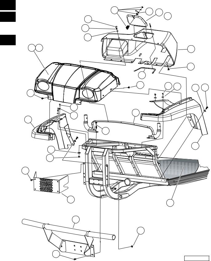
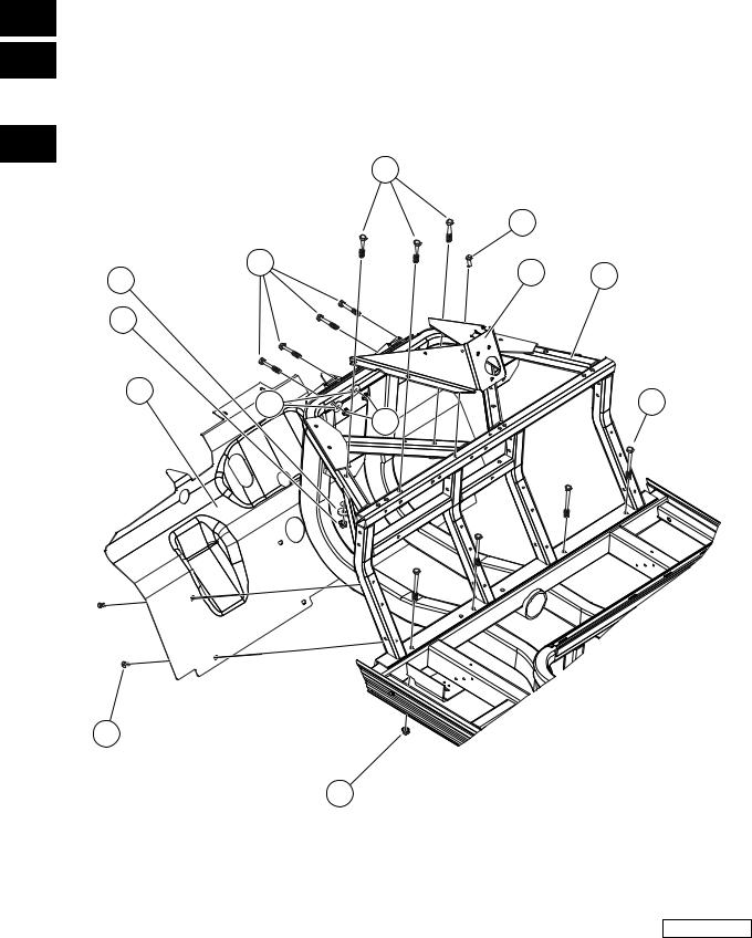
BODY AND TRIM 1
G
E
D

1
G
E
D
TYPICAL 5 PLACES
5 |
18 |
6 |
23 |
24 |
22 |
15 |
TYPICAL |
5 PLACES |
19 |
20 |
4 |
|
|
25 |
TYPICAL 2 PLACES
REF. |
25 |
3 |
|
25 |
TYPICAL |
|
7 PLACES |
||
|
13 |
|
TYPICAL |
TYPICAL |
3 PLACES |
4 PLACES |
25 |
TYPICAL |
18 |
1 |
|
|
6 PLACES |
1 |
18 |
|||
|
18 |
10 |
9 |
26 |
TYPICAL |
4 PLACES |
TYPICAL |
14 |
|
|
4 PLACES |
|
|
16 |
7 |
TYPICAL |
4 PLACES |
11 |
21 |
2 |
12 |
TYPICAL 4 PLACES
17 |
TYPICAL |
8 |
4 PLACES |
|
|
000148-001 |
Page 1-2 |
2005 HUV4420 and HUV4420-D Gasoline and Diesel Vehicles Illustrated Parts List |
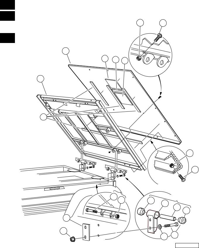
FRONT BODY TRIM, GASOLINE VEHICLES
ITEM |
PART NO. |
DESCRIPTION |
QTY |
|||
|
|
|
|
|
|
|
|
|
1 |
2 |
3 |
4 |
|
1 |
603 00 02-22 |
Washer, 1/4" Type B Flat ..................................................................................................... |
7 |
|||
2 |
603 00 06-74 |
Fender, Left Front ................................................................................................................ |
1 |
|||
3 |
603 00 06-76 |
Fender, Right Front .............................................................................................................. |
1 |
|||
4 |
603 00 06-78 |
Dashboard with Access Hole ............................................................................................... |
1 |
|||
5 |
603 00 07-29 |
Cap, 1/4" Plastic Screw Head ............................................................................................. |
5 |
|||
6 |
603 00 07-37 |
Washer, 1/4 Id Scalloped Plast ............................................................................................ |
5 |
|||
7 |
603 00 08-70 |
Screw, M8 X 1.25 X 30 Tri, Blk ............................................................................................ |
4 |
|||
8 |
603 00 08-75 |
Bolt, Flange Head, M8 X 30.0 ............................................................................................. |
4 |
|||
9 |
603 00 09-66 |
P-Clamp, Insulated .312 In .................................................................................................. |
1 |
|||
10 |
603 00 09-89 |
Weldment, Support, ROPS .................................................................................................. |
1 |
|||
11 |
603 00 10-04 |
Grill, Flat .............................................................................................................................. |
1 |
|||
12 |
603 00 10-11 |
Mat, Floor ............................................................................................................................ |
1 |
|||
13 |
603 00 11-51 |
Support, Access Panel, Dash .............................................................................................. |
1 |
|||
14 |
603 00 11-74 |
Washer Hard,m10 ............................................................................................................... |
4 |
|||
15 |
603 00 11-81 |
Rivet, .125" Dia, .311" Panel ............................................................................................... |
5 |
|||
16 |
603 00 13-00 |
Nut Flg M10 X 1.5 Mech Def ............................................................................................... |
4 |
|||
17 |
603 00 13-08 |
Lock Nut, Flg M8 X 1.25 Nylon ............................................................................................ |
4 |
|||
18 |
603 00 13-25 |
Screw, 1/4-20 X 1.0 Pn Hd Torx .......................................................................................... |
13 |
|||
19 |
603 00 16-75 |
Cowl, Camo ......................................................................................................................... |
1 |
|||
20 |
603 00 16-76 |
Cowl, Orange ....................................................................................................................... |
1 |
|||
21 |
603 00 17-69 |
Brush Guard ........................................................................................................................ |
1 |
|||
22 |
603 00 27-66 |
Panel, Access, Dash ........................................................................................................... |
1 |
|||
23 |
603 00 27-78 |
Cam Lock Body ................................................................................................................... |
1 |
|||
24 |
603 00 27-85 |
Latch, Cam, Access Panel .................................................................................................. |
1 |
|||
25 |
603 00 06-95 |
Rivet, Removable, Tuflok 1/4" ............................................................................................. |
15 |
|||
26 |
603 00 04-48 |
Bolt, M10 X 1.50 X 65 .......................................................................................................... |
4 |
|||
|
|
|
|
|
|
|
1
G
E
D
2005 HUV4420 and HUV4420-D Gasoline and Diesel Vehicles Illustrated Parts List |
Page 1-3 |
1
G
E
D
TYPICAL 5 PLACES
5 |
17 |
6 |
22 |
23 |
21 |
|
|
TYPICAL |
||
|
|
14 |
|
|
|
5 PLACES |
18 |
19 |
4 |
|
|
25 |
TYPICAL 2 PLACES
17 |
9 |
3 |
12 |
25 |
TYPICAL |
|
6 PLACES |
||
|
TYPICAL 3 PLACES
17 |
1 |
25 |
TYPICAL |
|
7 PLACES |
TYPICAL 4 PLACES
1 |
17 |
10 |
26 |
TYPICAL |
4 PLACES |
TYPICAL |
13 |
4 PLACES |
|
|
15 |
TYPICAL |
|
4 PLACES |
|
7 |
24 |
20 |
TYPICAL |
8 |
4 PLACES |
|
2 |
11 |
16 |
TYPICAL |
|
4 PLACES |
000149-001
Page 1-4 |
2005 HUV4420 and HUV4420-D Gasoline and Diesel Vehicles Illustrated Parts List |

FRONT BODY TRIM, DIESEL VEHICLES
ITEM |
PART NO. |
DESCRIPTION |
QTY |
|||
|
|
|
|
|
|
|
|
|
1 |
2 |
3 |
4 |
|
1 |
603 00 02-22 |
Washer, 1/4" Type B Flat ..................................................................................................... |
7 |
|||
2 |
603 00 06-74 |
Fender, Left Front ................................................................................................................ |
1 |
|||
3 |
603 00 06-76 |
Fender, Right Front .............................................................................................................. |
1 |
|||
4 |
603 00 06-78 |
Dashboard with Access Hole ............................................................................................... |
1 |
|||
5 |
603 00 07-29 |
Cap, 1/4" Plastic Screw Head ............................................................................................. |
5 |
|||
6 |
603 00 07-37 |
Washer, 1/4 Id Scalloped Plast ............................................................................................ |
5 |
|||
7 |
603 00 08-70 |
Screw, M8 X 1.25 X 30 Tri, Blk ............................................................................................ |
4 |
|||
8 |
603 00 08-75 |
Bolt, Flange Head, M8 X 30.0 ............................................................................................. |
4 |
|||
9 |
603 00 09-66 |
P-Clamp, Insulated .312 In .................................................................................................. |
1 |
|||
10 |
603 00 09-89 |
Weldment, Support, ROPS .................................................................................................. |
1 |
|||
11 |
603 00 10-11 |
Mat, Floor ............................................................................................................................ |
1 |
|||
12 |
603 00 11-51 |
Support, Access Panel, Dash .............................................................................................. |
1 |
|||
13 |
603 00 11-74 |
Washer Hard,m10 ............................................................................................................... |
4 |
|||
14 |
603 00 11-81 |
Rivet, .125" Dia, .311" Panel ............................................................................................... |
5 |
|||
15 |
603 00 13-00 |
Nut Flg M10 X 1.5 Mech Def ............................................................................................... |
4 |
|||
16 |
603 00 13-08 |
Lock Nut, Flg M8 X 1.25 Nylon ............................................................................................ |
4 |
|||
17 |
603 00 13-25 |
Screw, 1/4-20 X 1.0 Pn Hd Torx .......................................................................................... |
13 |
|||
18 |
603 00 16-75 |
Cowl, Camo ......................................................................................................................... |
1 |
|||
19 |
603 00 16-76 |
Cowl, Orange ....................................................................................................................... |
1 |
|||
20 |
603 00 17-69 |
Brush Guard ........................................................................................................................ |
1 |
|||
21 |
603 00 27-66 |
Panel, Access, Dash ........................................................................................................... |
1 |
|||
22 |
603 00 27-78 |
Cam Lock Body ................................................................................................................... |
1 |
|||
23 |
603 00 27-85 |
Latch, Cam, Access Panel .................................................................................................. |
1 |
|||
24 |
603 00 10-58 |
Guard, Radiator ................................................................................................................... |
1 |
|||
25 |
603 00 06-95 |
Rivet, Removable, Tuflok 1/4" ............................................................................................. |
15 |
|||
26 |
603 00 04-48 |
Bolt, M10 X 1.50 X 65 .......................................................................................................... |
4 |
|||
|
|
|
|
|
|
|
1
G
E
D
2005 HUV4420 and HUV4420-D Gasoline and Diesel Vehicles Illustrated Parts List |
Page 1-5 |
1
G
E
D
TYPICAL 3 PLACES
6 |
7 |
4 |
1 |
TYPICAL |
|
8 PLACES |
||
|
9 |
9 |
6 |
7 |
7 |
TYPICAL |
|
4 PLACES |
||
|
2 |
8 |
3 |
5 |
TYPICAL |
4 PLACES |
000017-001
Page 1-6 |
2005 HUV4420 and HUV4420-D Gasoline and Diesel Vehicles Illustrated Parts List |

FRONT BODY COMPONENTS
ITEM |
PART NO. |
DESCRIPTION |
QTY |
1 |
||||
|
|
|
|
|
|
|
|
|
|
|
1 |
2 |
3 |
4 |
|
|
G |
1 |
603 00 03-79 |
Blind Rivet, Push Type ........................................................................................................ |
8 |
|
||||
2 |
603 00 08-69 |
....................................................................................................Screw, M8X1.25X30, Hex |
1 |
|
E |
|||
3 |
**** |
Weldment, Dash, Front ........................................................................................................ |
1 |
|
||||
4 |
603 00 10-24 |
Guard, Splash ...................................................................................................................... |
1 |
|
|
|||
|
D |
|||||||
5 |
603 00 17-59 |
Bolt, M10x1.50x100 (Black) |
4 |
|
||||
|
|
|||||||
6 |
603 00 11-74 |
Washer Hard,m10 ............................................................................................................... |
7 |
|
|
|||
|
|
|||||||
7 |
603 00 13-00 |
Nut Flg M10 X 1.5 Mech Def ............................................................................................... |
11 |
|
|
|||
8 |
**** |
Bracket, Support, Steering ................................................................................................... |
1 |
|
|
|||
9 |
603 00 04-48 |
Bolt, M10 X 1.50 X 65 .......................................................................................................... |
7 |
|
|
|||
**** Special order item available upon request.
2005 HUV4420 and HUV4420-D Gasoline and Diesel Vehicles Illustrated Parts List |
Page 1-7 |
1
G
E
D
5 |
17 |
|
28 |
14 |
19 |
|
16 |
|
TYPICAL |
|
|
|
4 PLACES |
|
|
10 |
|
|
12 |
|
|
7 |
|
|
TYPICAL |
23 |
|
2 PLACES |
25 |
6 |
|
|
|
29 |
27 |
|
|
26 |
22 |
|
24 |
|
TYPICAL |
|
|
21 |
4 PLACES |
|
|
|
TYPICAL |
|
|
4 PLACES |
|
20 |
|
|
|
|
|
TYPICAL |
|
|
2 PLACES |
8 |
18 |
15 |
13 |
9
11
TYPICAL
4 PLACES
TYPICAL 2 PLACES
1 |
3 |
30 |
4 |
2 |
31 |
TYPICAL |
4 PLACES |
000028-001
Page 1-8 |
2005 HUV4420 and HUV4420-D Gasoline and Diesel Vehicles Illustrated Parts List |

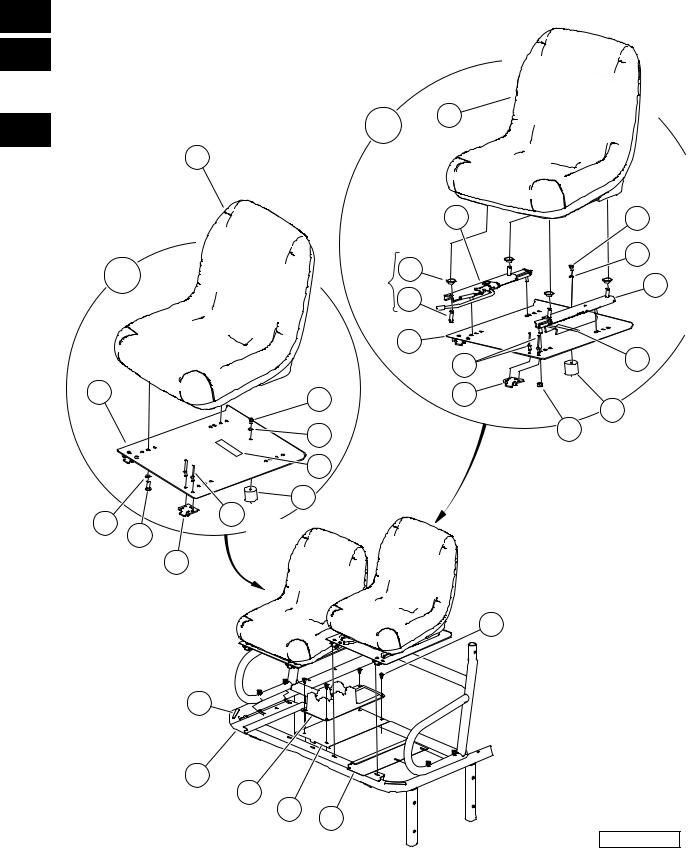
FRONT SEATS AND CUP HOLDER
ITEM |
PART NO. |
DESCRIPTION |
QTY |
|||
|
|
|
|
|
|
|
|
|
1 |
2 |
3 |
4 |
|
1 |
603 00 02-29 |
Tape, Vinyl Foam 1/8" x 3/4" ............................................................................................... |
2 |
|||
2 |
603 00 09-98 |
Closeout, Driver Side ........................................................................................................... |
1 |
|||
3 |
603 00 09-99 |
Closeout, Passenger Side ................................................................................................... |
1 |
|||
4 |
603 00 10-49 |
Pan, Center, Closeout ......................................................................................................... |
1 |
|||
5 |
531 30 82-51 |
Asm, Bucket Seat Adjustable (includes items 6 through 18) ............................................... |
1 |
|||
6 |
603 00 01-25 |
|
Hinge Plate ..................................................................................................................... |
2 |
||
7 |
603 00 07-36 |
|
Rivet, 1/4 X .438 Blind .................................................................................................... |
4 |
||
8 |
603 00 07-74 |
|
Screw, 6m-1.00 X 10mm Hex Head ................................................................................ |
1 |
||
9 |
603 00 07-77 |
|
Seat Holder Cup ............................................................................................................. |
1 |
||
10 |
603 00 08-75 |
|
Bolt, Flange Head, M8 X 30.0 ......................................................................................... |
4 |
||
11 |
603 00 12-98 |
|
Nut,m8,all Metal Lock ..................................................................................................... |
4 |
||
12 |
603 00 10-93 |
|
Pan, Seat, Driver Asm .................................................................................................... |
1 |
||
13 |
603 00 11-02 |
|
Decal, Hot Surface Warning ............................................................................................ |
1 |
||
14 |
603 00 11-37 |
|
Adjuster, Forward/Aft ...................................................................................................... |
1 |
||
15 |
603 00 11-38 |
|
Adjuster, Slider ................................................................................................................ |
1 |
||
16 |
603 00 11-45 |
|
Washer, Bell .................................................................................................................... |
4 |
||
17 |
603 00 40-79 |
|
Seat, Bucket, Gray .......................................................................................................... |
1 |
||
18 |
603 00 00-58 |
|
Lockwasher, 1/4 Helical Split .......................................................................................... |
1 |
||
19 |
N/A |
Assembly, Bucket Seat w/Spacers (includes items 20 through 29) ..................................... |
1 |
|||
20 |
603 00 01-25 |
|
Hinge Plate ..................................................................................................................... |
2 |
||
21 |
603 00 05-79 |
|
Screw, M8-125 X 22 Hex-Head ...................................................................................... |
4 |
||
22 |
603 00 01-84 |
|
Lockwasher, 8mm Split ................................................................................................... |
4 |
||
23 |
603 00 06-89 |
|
Pan, Seat, Passenger ..................................................................................................... |
1 |
||
24 |
603 00 07-36 |
|
Rivet, 1/4 X .438 Blind .................................................................................................... |
4 |
||
25 |
603 00 07-74 |
|
Screw, 6m-1.00 X 10mm Hex Head ................................................................................ |
1 |
||
26 |
603 00 07-77 |
|
Seat Holder Cup ............................................................................................................. |
1 |
||
27 |
603 00 11-02 |
|
Decal, Hot Surface Warning ............................................................................................ |
1 |
||
28 |
603 00 40-79 |
|
Seat, Bucket, Gray .......................................................................................................... |
1 |
||
29 |
603 00 00-58 |
|
Lockwasher, 1/4 Helical Split .......................................................................................... |
1 |
||
30 |
603 00 11-61 |
Console, Center, Drink Holder ............................................................................................. |
1 |
|||
31 |
603 00 06-95 |
Rivet, Removable, Tuflok 1/4" ............................................................................................. |
4 |
|||
|
|
|
|
|
|
|
1
G
E
D
2005 HUV4420 and HUV4420-D Gasoline and Diesel Vehicles Illustrated Parts List |
Page 1-9 |
1
G
E
D
5 |
4 |
3 |
6 |
12 |
|
|
11 |
|
|
15 |
14 |
|
|
13 |
|
|
|
TYPICAL 8 PLACES
10
16
TYPICAL
4 PLACES
21
7
|
17 |
|
|
TYPICAL |
|
FRONT |
4 PLACES |
|
18 |
||
OF VEHICLE |
||
|
TYPICAL |
TYPICAL |
|
2 PLACES |
||
2 PLACES |
||
|
22 |
21 |
|
21 |
23 |
|
|
|
||
|
|
|
|
|
|
TYPICAL |
19 |
|
|
|
2 PLACES |
|
||
|
8 |
20 |
|
|
25 |
TYPICAL 2 PLACES
2 |
27 |
|
26 |
|
TYPICAL |
|
2 PLACES |
|
1 |
9 |
|
20 |
|
TYPICAL |
|
2 PLACES |
24 |
|
000029-001
Page 1-10 |
2005 HUV4420 and HUV4420-D Gasoline and Diesel Vehicles Illustrated Parts List |

|
|
|
|
|
|
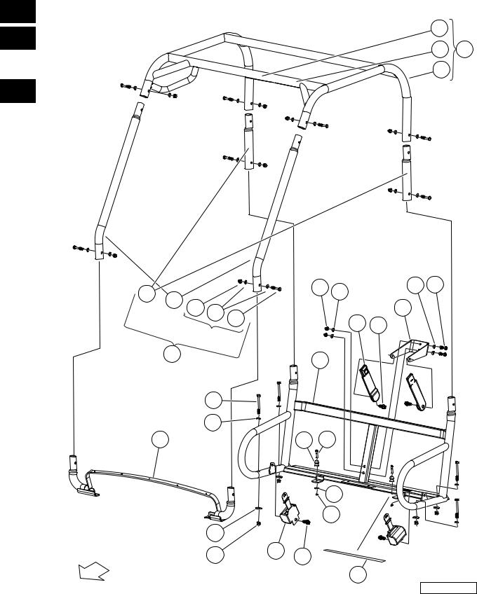
ROPS |
|
ITEM |
PART NO. |
DESCRIPTION |
|
QTY |
|||
|
|
|
|
|
|
|
|
|
|
1 |
2 |
3 |
4 |
|
|
1 |
603 00 05-58 |
Locknut, M6-1.00 Nylon Insert ............................................................................................. |
|
2 |
|||
2 |
603 00 07-73 |
Seat Holder Base ................................................................................................................ |
|
2 |
|||
3 |
603 00 09-88 |
Weldment, Top, ROPS (includes items 4 through 6) ........................................................... |
|
1 |
|||
4 |
603 00 11-06 |
|
Decal, Young Driver Warning .......................................................................................... |
|
1 |
||
5 |
603 00 13-14 |
|
Decal, ROPS Certification/Warning ................................................................................ |
|
1 |
||
6 |
603 00 36-06 |
|
Weldment, ROPS, Top, Unlabeled .................................................................................. |
|
1 |
||
7 |
603 00 09-89 |
Weldment, Support, ROPS .................................................................................................. |
|
1 |
|||
8 |
603 00 10-65 |
Buckle, Seat Belt with Sleeve .............................................................................................. |
|
2 |
|||
9 |
603 00 10-66 |
Retractor, Seat Belt ............................................................................................................. |
|
2 |
|||
10 |
603 00 11-60 |
Kit, ROPS (includes items 11 through 15) ........................................................................... |
|
1 |
|||
11 |
603 00 09-90 |
|
Tube, Support, Front, ROPS ........................................................................................... |
|
2 |
||
12 |
603 00 09-91 |
|
Tube, Support, Rear, ROPS ............................................................................................ |
|
2 |
||
13 |
603 00 16-72 |
|
Bolt, M10 X 55, Zn-Ni (Black) ......................................................................................... |
|
8 |
||
14 |
603 00 16-73 |
|
Washer, Hard, M10, Zn-Ni/Blk ........................................................................................ |
|
16 |
||
15 |
603 00 16-74 |
|
Nut, Hex Cap, M10, Zn-Ni/Blk ......................................................................................... |
|
8 |
||
16 |
603 00 17-59 |
Bolt, M10x1.50x100 (Black) ................................................................................................. |
|
4 |
|||
17 |
603 00 11-74 |
Washer Hard,m10 ............................................................................................................... |
|
4 |
|||
18 |
603 00 13-00 |
Nut Flg M10 X 1.5 Mech Def ............................................................................................... |
|
4 |
|||
19 |
603 00 15-85 |
Bracket, Seatbelt, Bolt-On ................................................................................................... |
|
1 |
|||
20 |
603 00 15-89 |
Screw,m12x1.75x30 Thd Form Blk ...................................................................................... |
|
4 |
|||
21 |
603 00 16-73 |
Washer, Hard, M10, Zn-Ni/Blk ............................................................................................. |
|
8 |
|||
22 |
603 00 16-74 |
Nut, Hex Cap, M10, Zn-Ni/Blk ............................................................................................. |
|
2 |
|||
23 |
603 00 17-60 |
Bolt, M10 X 45, Zn-Ni (Black) .............................................................................................. |
|
2 |
|||
24 |
603 00 17-66 |
Barrier, Heat, Neoprene ....................................................................................................... |
|
1 |
|||
25 |
603 00 09-87 |
Weldment, Supp, Seat, Rops .............................................................................................. |
|
1 |
|||
26 |
603 00 00-54 |
Washer, 1/4 Type A Narrow Flat .......................................................................................... |
|
2 |
|||
27 |
603 00 04-52 |
Bolt, M6 X 1 X 45 ................................................................................................................. |
|
2 |
|||
|
|
|
|
|
|
|
|
1
G
E
D
2005 HUV4420 and HUV4420-D Gasoline and Diesel Vehicles Illustrated Parts List |
Page 1-11 |
1
G
E
D
9 |
11 |
8 |
9.4 FEET
2TYPICALPLACES |
16 |
|
TYPICAL |
4 |
|
4 PLACES |
||
|
15 |
7 |
|
TYPICAL |
|
8 PLACES |
12 |
13 |
14 |
|
||
|
|
TYPICAL 2 PLACES
15 |
10 |
TYPICAL 4 PLACES
19 |
|
18 |
3 |
TYPICAL 2 PLACES
2
1
3
5 |
17 |
TYPICAL |
|
2 PLACES |
|||
|
000157-001
Page 1-12 |
2005 HUV4420 and HUV4420-D Gasoline and Diesel Vehicles Illustrated Parts List |
TILT BED AND HINGE
ITEM |
PART NO. |
DESCRIPTION |
QTY |
|
1 |
|||
|
|
|
|
|
|
|
|
|
|
|
1 |
2 |
3 |
4 |
|
|
G |
1 |
603 00 01-36 |
Bushing, Steel ..................................................................................................................... |
2 |
|
||||
2 |
603 00 02-50 |
Hinge |
................................................................................................................................... |
|
2 |
|
E |
|
3 |
603 00 02-63 |
Bushing, Urethane ............................................................................................................... |
2 |
|
||||
4 |
603 00 07-80 |
Locknut, 3/8-16 Flanged Dimple .......................................................................................... |
4 |
|
|
|||
|
D |
|||||||
5 |
603 00 07-81 |
Washer, 3/8 Type B Hard Flat |
4 |
|
||||
|
|
|||||||
6 |
603 00 07-97 |
Assembly, Tilt Bed, Electric Lift (includes items 7 through 14) ............................................ |
1 |
|
|
|||
|
|
|||||||
7 |
603 00 01-07 |
|
Bolt, Carriage, 5/16-18 X 1.00 ........................................................................................ |
4 |
|
|
||
8 |
603 00 02-29 |
|
Tape, Vinyl Foam 1/8" x 3/4" ........................................................................................... |
A/R |
|
|
||
9 |
N/A |
|
Plate, Floor Bed .............................................................................................................. |
1 |
|
|
||
10 |
N/A |
|
Frame Assembly ............................................................................................................. |
A/R |
|
|
||
11 |
603 00 02-55 |
|
Screw, 5/16-18 X 0.88 Torx Truss-Head ......................................................................... |
4 |
|
|
||
12 |
603 00 18-12 |
|
Foam, Barrier, Heat, Bed, Frt .......................................................................................... |
1 |
|
|
||
13 |
603 00 16-04 |
|
Foam, Barrier, Heat, Bed, Rail ........................................................................................ |
1 |
|
|
||
14 |
603 00 00-78 |
|
Locknut, 5/16-18 Nylon Insert ......................................................................................... |
8 |
|
|
||
15 |
603 00 12-86 |
Plate, Back .......................................................................................................................... |
2 |
|
|
|||
16 |
603 00 00-80 |
Bolt, 3/8-16 X 3.00 Hex Head .............................................................................................. |
4 |
|
|
|||
17 |
603 00 00-95 |
Locknut, 3/8-16 Hex ............................................................................................................ |
2 |
|
|
|||
18 |
603 00 00-96 |
Screw, 3/8-16 X 3.375 Hex Cap .......................................................................................... |
2 |
|
|
|||
|
|
|
|
|
|
|
|
|
2005 HUV4420 and HUV4420-D Gasoline and Diesel Vehicles Illustrated Parts List |
Page 1-13 |
1
G
E
D
6 |
14 |
10 |
4 |
6 |
15 |
1 |
TYPICAL |
15 |
4 PLACES |
||
6 |
6 |
|
|
|
7 |
TYPICAL |
2 PLACES |
6 
14 |
14 |
TYPICAL 4 PLACES
9 |
8 |
3
TYPICAL |
5 |
2 PLACES |
|
13 |
14 |
2 |
13 |
15 |
5 |
2 |
8 |
|
||
TYPICAL |
|
REF. |
|
|
|
2 PLACES |
|
|
12 |
16 TYPICAL |
5 PLACES |
TYPICAL 2 PLACES
11 |
000158-001
Page 1-14 |
2005 HUV4420 and HUV4420-D Gasoline and Diesel Vehicles Illustrated Parts List |
ELECTRIC BED LIFT
ITEM |
PART NO. |
DESCRIPTION |
QTY |
|
1 |
|||
|
|
|
|
|
|
|
|
|
|
|
1 |
2 |
3 |
4 |
|
|
G |
1 |
603 00 01-06 |
Bolt, 3/8-16 X 4.25 Hex Head .............................................................................................. |
1 |
|
||||
2 |
603 00 03-65 |
.......................................................................................................................Bushing Long |
2 |
|
E |
|||
3 |
603 00 03-84 |
Actuator Assembly, Electric ................................................................................................. |
1 |
|
||||
4 |
603 00 03-85 |
Asm, Actuator Adapter ........................................................................................................ |
1 |
|
|
|||
|
D |
|||||||
5 |
603 00 04-34 |
Body Spacer |
8 |
|
||||
|
|
|||||||
6 |
603 00 07-81 |
Washer, 3/8 Type B Hard Flat ............................................................................................. |
8 |
|
|
|||
|
|
|||||||
7 |
603 00 10-01 |
Bumper, Bed, Mtg, Front ..................................................................................................... |
2 |
|
|
|||
8 |
603 00 11-27 |
Weldment, Bracket, Actuator ............................................................................................... |
1 |
|
|
|||
9 |
603 00 12-86 |
Plate, Back .......................................................................................................................... |
1 |
|
|
|||
10 |
603 00 13-08 |
Lock Nut, Flg M8 X 1.25 Nylon ............................................................................................ |
2 |
|
|
|||
11 |
603 00 13-27 |
Tie Wrap, 8.00" With Mount ................................................................................................. |
2 |
|
|
|||
12 |
603 00 15-95 |
Wire Harness, Electric Lift ................................................................................................... |
1 |
|
|
|||
13 |
603 00 00-56 |
Washer, Lock, Hel Sp 3/8 Reg ............................................................................................. |
2 |
|
|
|||
14 |
603 00 00-95 |
Locknut, 3/8-16 Hex ............................................................................................................ |
9 |
|
|
|||
15 |
603 00 00-96 |
Screw, 3/8-16 X 3.375 Hex Cap .......................................................................................... |
6 |
|
|
|||
16 |
603 00 29-63 |
Tie Wrap, 8" Nylon ............................................................................................................... |
5 |
|
|
|||
|
|
|
|
|
|
|
|
|
2005 HUV4420 and HUV4420-D Gasoline and Diesel Vehicles Illustrated Parts List |
Page 1-15 |
1
G
E
D
TYPICAL 4
PLACES
4 |
9 |
TYPICAL 4
PLACES
24 |
26 |
|
1 |
TYPICAL 2
PLACES
11
10 |
TYPICAL 2
PLACES
12 |
6 |
25 |
|
8 |
5 |
7 |
|
|
13 |
3
4 |
6 |
25 |
25 |
21 |
17 |
16 |
PASSENGER SIDE |
19 |
|
14 |
DRIVER SIDE |
20 |
22 |
15
TYPICAL 4
PLACES
18 |
TYPICAL 2
PLACES
TYPICAL 16
PLACES
2 |
|
TYPICAL 4 |
23 |
PLACES |
000038-002
Page 1-16 |
2005 HUV4420 and HUV4420-D Gasoline and Diesel Vehicles Illustrated Parts List |

|
|
|
|
|
|
CARGO BOX |
|
ITEM |
PART NO. |
DESCRIPTION |
|
QTY |
|||
|
|
|
|
|
|
|
|
|
|
1 |
2 |
3 |
4 |
|
|
1 |
603 00 01-07 |
Bolt, Carriage, 5/16-18 X 1.00 ............................................................................................. |
|
13 |
|||
2 |
603 00 01-08 |
Bumper, Rubber .................................................................................................................. |
|
4 |
|||
3 |
603 00 02-22 |
Washer, 1/4" Type B Flat ..................................................................................................... |
|
4 |
|||
4 |
603 00 02-26 |
Screw, 1/4-20 X 0.75 Torx Truss-Head ................................................................................ |
|
8 |
|||
5 |
603 00 02-32 |
Stud, Self-Clinching Flush Head .......................................................................................... |
|
4 |
|||
6 |
603 00 02-55 |
Screw, 5/16-18 X 0.88 Torx Truss-Head .............................................................................. |
|
18 |
|||
7 |
603 00 05-73 |
Box Bed Tailgate Angle ....................................................................................................... |
|
1 |
|||
8 |
603 00 06-16 |
Locknut, 5/16-18 Hex Flange .............................................................................................. |
|
4 |
|||
9 |
603 00 08-02 |
Front Panel Weldment ......................................................................................................... |
|
1 |
|||
10 |
603 00 08-03 |
Left Panel Weldment ........................................................................................................... |
|
1 |
|||
11 |
603 00 08-04 |
Right Panel Weldment ......................................................................................................... |
|
1 |
|||
12 |
603 00 08-05 |
Front Corner Cap ................................................................................................................. |
|
2 |
|||
13 |
603 00 08-07 |
Slam Latch ........................................................................................................................... |
|
2 |
|||
14 |
603 00 08-13 |
Assembly, Tailgate (includes items 15 through 22) ............................................................. |
|
1 |
|||
15 |
603 00 01-72 |
|
Hair Pin Clip .................................................................................................................... |
|
4 |
||
16 |
603 00 02-26 |
|
Screw, 1/4-20 X 0.75 Torx Truss-Head ........................................................................... |
|
4 |
||
17 |
N/A |
|
Tailgate, Weldment ......................................................................................................... |
|
1 |
||
18 |
603 00 08-06 |
|
Tether Assembly ............................................................................................................. |
|
2 |
||
19 |
603 00 08-08 |
|
Spring Latch Left ............................................................................................................. |
|
1 |
||
20 |
603 00 08-09 |
|
Spring Latch Right ........................................................................................................... |
|
1 |
||
21 |
603 00 17-92 |
|
Decal, Husqvarna, Tailgate ............................................................................................. |
|
1 |
||
22 |
603 00 00-89 |
|
Locknut, 1/4-20 Nylon Insert ........................................................................................... |
|
4 |
||
23 |
603 00 08-16 |
Washer, Rubber, 3/8 ............................................................................................................ |
|
4 |
|||
24 |
603 00 00-54 |
Washer, 1/4 Type A Narrow Flat .......................................................................................... |
|
4 |
|||
25 |
603 00 00-78 |
Locknut, 5/16-18 Nylon Insert .............................................................................................. |
|
31 |
|||
26 |
603 00 00-89 |
Locknut, 1/4-20 Nylon Insert ................................................................................................ |
|
4 |
|||
|
|
|
|
|
|
|
|
1
G
E
D
2005 HUV4420 and HUV4420-D Gasoline and Diesel Vehicles Illustrated Parts List |
Page 1-17 |
1
G
E
D
7 |
12 |
9 |
17 |
3
TYPICAL
2 PLACES
4
22 |
TYPICAL |
|
4 PLACES |
13 |
TYPICAL 2 PLACES
13 |
13 |
15
TYPICAL
4 PLACES
14 |
TYPICAL |
|
2 PLACES |
5 |
6 |
20 |
19 |
21 |
TYPICAL 4 PLACES
11 |
18 |
10 |
16 |
|
|
TYPICAL 5 PLACES
22 |
TYPICAL 4 PLACES
2
|
1 |
TYPICAL |
8 |
|
2 PLACES |
|
|
|
2 |
22 |
|
TYPICAL
6 PLACES
FRONT
OF VEHICLE
000150-001
Page 1-18 |
2005 HUV4420 and HUV4420-D Gasoline and Diesel Vehicles Illustrated Parts List |
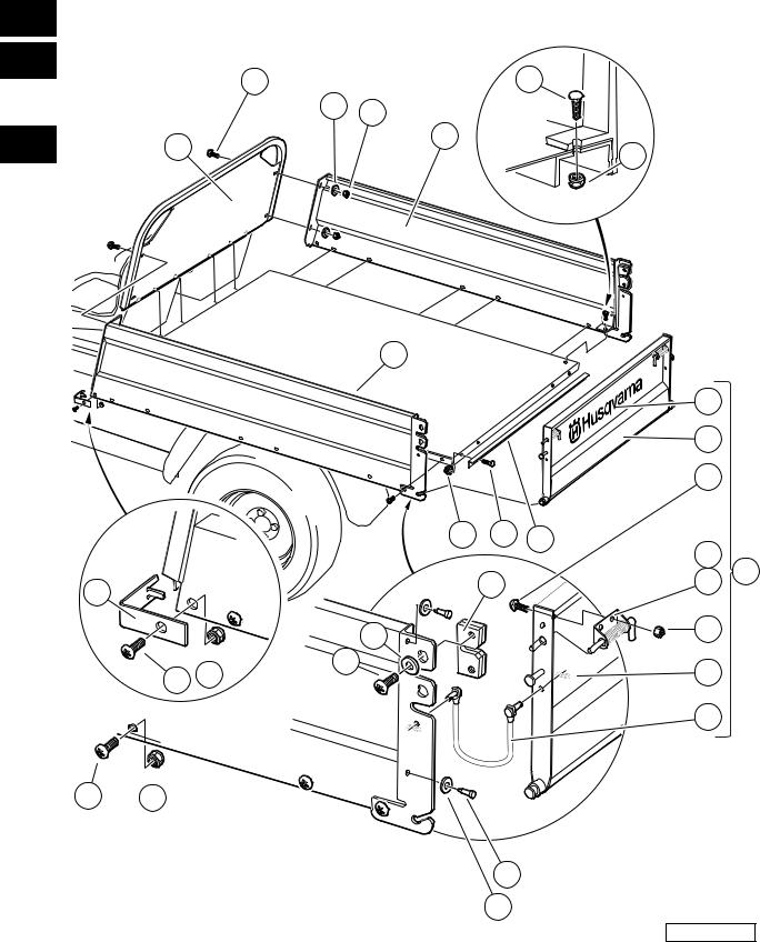
REAR BODY TRIM
ITEM |
PART NO. |
DESCRIPTION |
QTY |
|
1 |
|||
|
|
|
|
|
|
|
|
|
|
|
1 |
2 |
3 |
4 |
|
|
G |
1 |
603 00 01-57 |
Screw, M6-1.00 X 25mm Hex Cap ...................................................................................... |
2 |
|
||||
2 |
603 00 02-22 |
.....................................................................................................Washer, 1/4" Type B Flat |
8 |
|
E |
|||
3 |
603 00 02-23 |
Screw, #10 Truss-Head Torx ............................................................................................... |
2 |
|
||||
4 |
603 00 04-58 |
Corner Cap AWD ................................................................................................................. |
2 |
|
|
|||
|
D |
|||||||
5 |
603 00 06-93 |
Side Step Bar (black) |
2 |
|
||||
|
|
|||||||
6 |
603 00 06-94 |
Side Step Bar (orange) ........................................................................................................ |
2 |
|
|
|||
|
|
|||||||
7 |
603 00 26-90 |
Fender, Right Rear .............................................................................................................. |
1 |
|
|
|||
8 |
603 00 26-91 |
Fender, Left Rear ................................................................................................................. |
1 |
|
|
|||
9 |
603 00 10-85 |
Assembly, Panel (Passenger Side) ..................................................................................... |
1 |
|
|
|||
10 |
603 00 10-86 |
Assembly, Panel (Driver Side) ............................................................................................. |
1 |
|
|
|||
11 |
603 00 10-87 |
Panel, Front ......................................................................................................................... |
1 |
|
|
|||
12 |
603 00 11-29 |
Bezel, Fuel Fill ..................................................................................................................... |
1 |
|
|
|||
13 |
603 00 11-76 |
Well Nut 1/4-20 .................................................................................................................... |
14 |
|
|
|||
14 |
603 00 13-17 |
Nut Flg, M6 X 1.0 Nylon ...................................................................................................... |
2 |
|
|
|||
15 |
603 00 15-99 |
Washer, M12 Hard Regular ................................................................................................. |
2 |
|
|
|||
16 |
603 00 17-74 |
Panel, Side, Driver, Steel ..................................................................................................... |
1 |
|
|
|||
17 |
603 00 17-75 |
Panel, Side, Passenger, Steel ............................................................................................. |
1 |
|
|
|||
18 |
603 00 17-76 |
Panel, Front, Steel ............................................................................................................... |
1 |
|
|
|||
19 |
603 00 00-56 |
Washer, Lock, Hel Sp 3/8 Reg ............................................................................................. |
4 |
|
|
|||
20 |
603 00 00-80 |
Bolt, 3/8-16 X 3.00 Hex Head .............................................................................................. |
4 |
|
|
|||
21 |
603 00 36-17 |
Washer, 3/8 Type B Flat ...................................................................................................... |
4 |
|
|
|||
22 |
603 00 00-91 |
Screw, 1/4-20 X 1.0 Truss-Head Machine ........................................................................... |
14 |
|
|
|||
|
|
|
|
|
|
|
|
|
2005 HUV4420 and HUV4420-D Gasoline and Diesel Vehicles Illustrated Parts List |
Page 1-19 |
1
G
E
D
4 |
5 |
2 |
TYPICAL |
3 |
|
34 PLACES |
|
000165-001
Page 1-20 |
2005 HUV4420 and HUV4420-D Gasoline and Diesel Vehicles Illustrated Parts List |
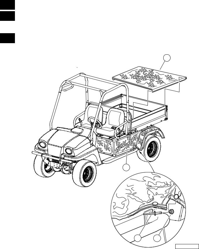
CAMOUFLAGE COVERS
ITEM |
PART NO. |
DESCRIPTION |
QTY |
|
1 |
|||
|
|
|
|
|
|
|
|
|
|
|
1 |
2 |
3 |
4 |
|
|
G |
1 |
603 00 00-45 |
Kit, Camouflage Cover (includes items 2 through 5) ........................................................... |
1 |
|
||||
2 |
N/A |
|
. ............................................................................................................Rivet, 0.125" Dia |
34 |
|
E |
||
3 |
N/A |
|
Snap, Male Button, 7/16" ................................................................................................ |
34 |
|
|||
4 |
603 00 00-26 |
|
Cover, Camouflage Cargo Box (Forest Floor Pattern) .................................................... |
1 |
|
|
||
|
|
D |
||||||
5 |
531 30 10-26 |
|
Wrap, Camouflage Rear Body (Forest Floor Pattern) |
1 |
|
|||
|
|
|
||||||
|
|
|
|
|
|
|
|
|
|
|
|
|
|
|
|
|
|
2005 HUV4420 and HUV4420-D Gasoline and Diesel Vehicles Illustrated Parts List |
Page 1-21 |

1
G
E
D
Loading...