


I |
n |
s |
t |
a |
l |
l |
a |
t |
i |
o |
n |
G |
u |
i |
d |
e |
|
|
|
|
|
|
|
|
|
|
|
|
|
|
|
|
|
ENGLISH 2 page See |
|
|
|
|
|
|
|
|
|
|
|
|
|
|
|
|
|
21 página la Vea |
Español |
90063/90064 Ellipse™ Bath Ventilator with Light and Night Light
READ and SAVE THESE INSTRUCTIONS
41722-01 3/29/2006
41722_EngS_3.29.03.indd 1 |
|
|
3/29/06 10:54:38 PM |
|
|
||
|
|
|
|
 W a r n i n g
TO REDUCE THE RISK OF ELECTRIC SHOCK OR INJURY, OBSERVE THE FOLLOWING:
1.Use this unit only in a manner intended by the manufacturer. If you have questions, contact the manufacturer at the phone number or address listed in the warranty.
2.Before installing, servicing, or cleaning the unit, disconnect the power by turning off the circuit breakers to the outlet box and associated wall switch location. If you cannot lock the circuit breakers in the off position, securely attach a prominent warning device, such as a tag, to the service panel.
3.Installation work and electrical wiring must be done by qualified person(s) in accordance with all applicable codes and standards, including fire-rated construction codes and standards.
4.Sufficient air is needed for proper combustion and exhausting of gasses through the flue (chimney) of fuel burning equipment to prevent backdrafting. Follow the heating equipment manufacturer’s guideline and safety standards,
such as those published by the National Fire Prevention Association (NFPA), and the American Society for Heating, Refrigeration and Air-Conditioning Engineers (ASHRAE), and the local code authorities.
5.When cutting or drilling into wall(s) or ceiling, do not damage electrical wiring or other hidden utilities.
6.Ducted fans must always be vented to the outdoors. Keep ducting as short and as straight as possible.
7.Acceptable for use over a bathtub or shower when connected to a GFCI protected branch circuit.
8.Install fan at least 5 feet (1.52 m) above the floor.
9.Never place a switch where it can be reached from a tub or shower.
10.This unit must be grounded.
 C A U T I O N
1.For general ventilating use only. Do not use for ventilating hazardous or explosive materials.
2.To avoid motor bearing damage and noisy/unbalanced impellers, keep drywall spray, construction dust, etc. off power unit.
3.DO NOT install this product in a wall. This product is designed for installation in ceilings up to a 12/12 pitch (45 degrees). Ductwork must point upward.
4.Please read specification label on product for further information and requirements.
 W a r n i n g
DISCONNECT
ELECTRIC
POWER SUPPLY AND LOCK OUT SERVICE PANEL BEFORE SERVICING UNIT
PREVENTATIVE MAINTENANCE
A clean fan provides better service. Disconnect the power supply and clean the fan as listed below.
TO CLEAN GRILLE: Use a mild detergent, such as dishwashing liquid, and a soft cloth. DO NOT use abrasive cloths, steel wool pads or scouring powders.
TO CLEAN FAN ASSEMBLY: Unplug motor cord from receptacle. To remove motor plate, find the single tab on the motor plate (located next to the receptacle). Push up rear motor plate tab while pushing out on the side of the housing or insert a screwdriver into the slot in the housing (next to tab) and twist screwdriver. Gently vacuum fan, motor and interior of housing.
METAL AND ELECTRICAL PARTS SHOULD NEVER BE IMMERSED IN WATER.
MAINTENANCE
The motor is permanently lubricated and never needs oiling. If the motor bearings are making excessive or unusual noises, replace the motor with the exact service motor. You should replace the impeller at the same time.
2 |
41722-01 3/29/2006 |
||
41722_EngS_3.29.03.indd 2 |
|
|
3/29/06 10:54:39 PM |
|
|
||
|
|
||
|
|
|
|
|
|
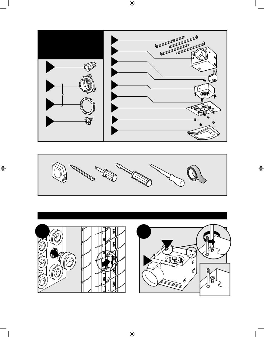
Check all the parts. |
|
D |
95044-01-000 |
|
|
If damaged, call |
|
||
|
|
|
|
||
|
|
1-888-830-1326 |
|
E |
95022-01-000 |
|
|
for replacements. |
|
|
|
|
|
|
|
|
|
|
|
|
|
F |
75190-01-000 |
x5 |
A |
|
|
|
|
|
|
G |
03242-07-133 |
||
|
|
|
|
||
|
|
|
|
|
|
* B |
|
|
H |
95492-01-000 |
|
|
|
|
|||
|
|
|
74508-03-133 |
||
|
|
3/8” Cable Connector |
x2 |
I |
|
|
|
|
|
||
* C |
|
|
J |
95510-01-000 |
|
x2 |
I |
|
|
K |
75184-01-133 |
Extra Screws |
|
|
|||
* |
NOTE: Strain relief cable connector |
|
L |
95366-01/02-000 |
|
|
|
||||
|
|
must be installed. Not Included. |
|
|
|
|
|
|
|
|
Included. |
Tools Needed. (Not supplied)
Estimated assembly time: 30 to 60 minutes
Before Installation
NOTE: Remove all packing materials before installation.
1 |
2 |
|
|
|
30 |
|
30 |
|
30 |
|
0 |
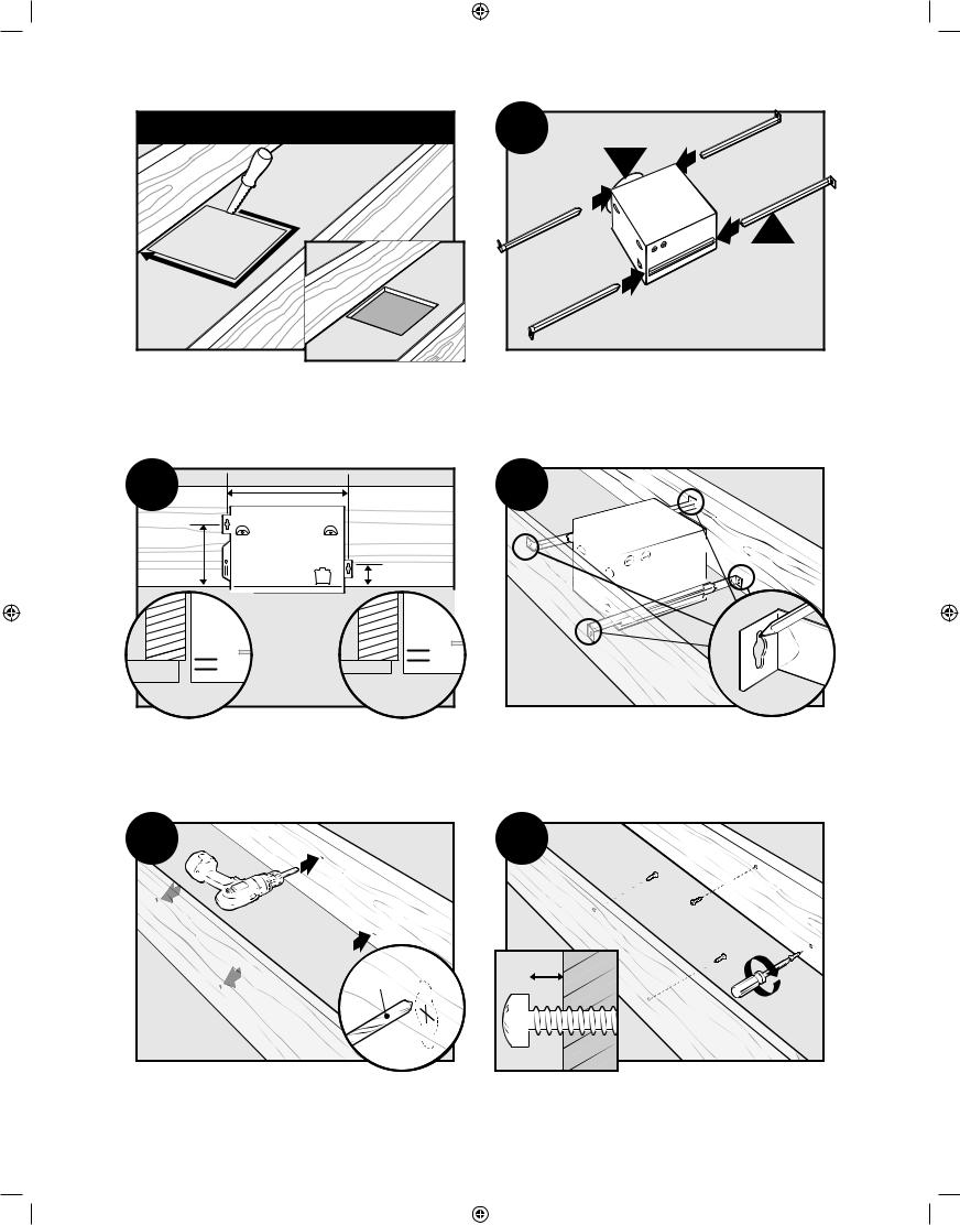
Turn off the power source.
2 |
I |
E |
Loosen screws.
41722-01 3/29/2006 |
3 |
41722_EngS_3.29.03.indd 3 |
3/29/06 10:54:41 PM |
3 |
4 |
H |
|
|
E |
Remove the motor/blower from the housing. |
Remove packing material. |
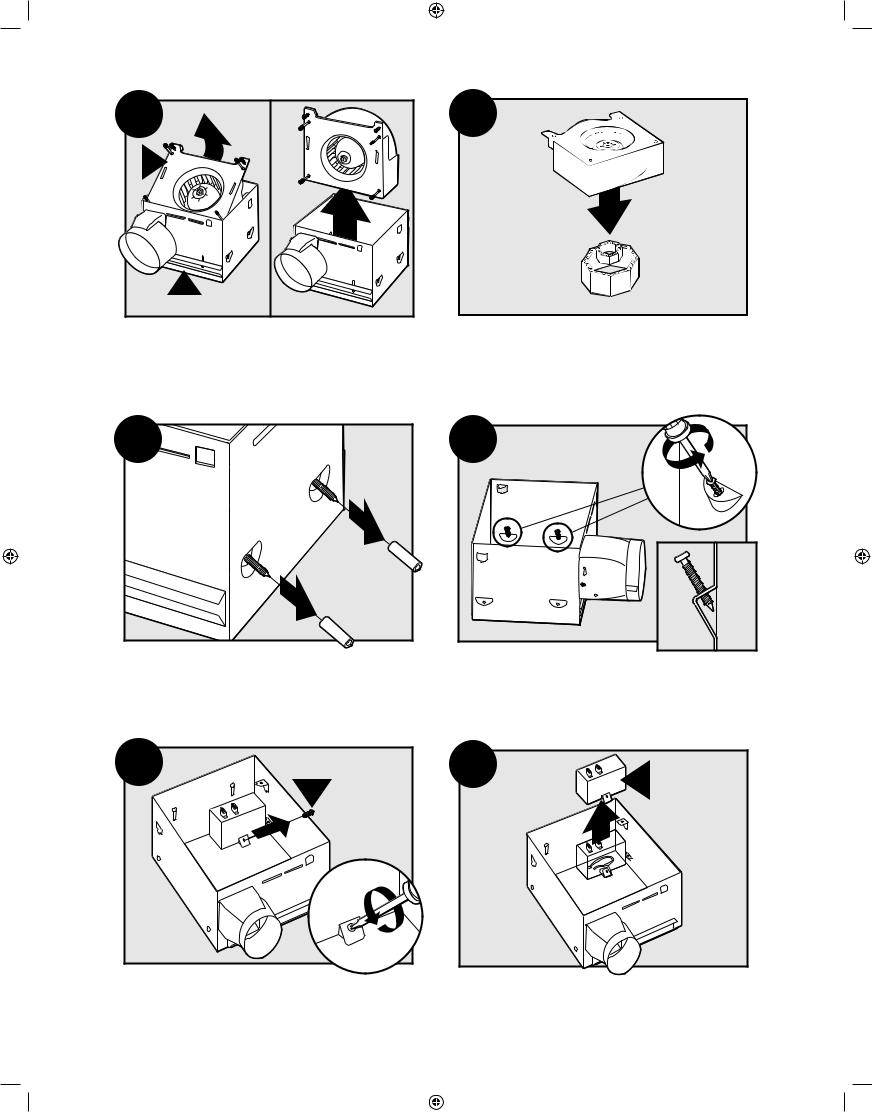
5 |
Remove the pre-loaded screw tip covers.
7 |
G |
Remove the wiring cover screw.
6 |
Back out the pre-loaded screw tips until flush with the side of the housing.
8 |
F |
|
Remove the wiring cover.
4 |
41722-01 3/29/2006 |
||
41722_EngS_3.29.03.indd 4 |
|
|
3/29/06 10:54:44 PM |
|
|
||
|
|
||
|
|
|
|
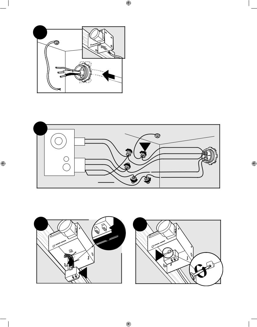
9
E
Pop out the first wiring access slug. Use second if needed.
Insert the strain relief into the housing and secure with the washer.
Choose Installation Option
For New Construction - attaching to joist go to step A11, page 5
For New Construction - suspended between joists go to step B11, page 8 For Existing Construction - accessible from above go to step C11, page 11 For Existing Construction - accessible only from below go to step D11, page15
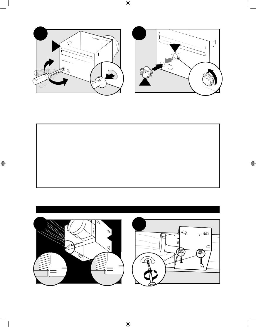
New Construction – attaching to joist |
|
|
A11 |
|
A12 |
|
E |
|
5/8 |
5/8 |
|
1/2 |
|
|
1/2 |
|
|
|
|
|
Position the correct depth mark at the bottom edge of the |
Screw pre-loaded screws into joist or framing. |
joist based on the thickness of your sheetrock. |
|
41722-01 3/29/2006
41722_EngS_3.29.03.indd 5
5
3/29/06 10:54:46 PM
A13 |
Pull wires through the strain relief.
A14 |
|
|
|
Ground |
|
|
|
Black |
|
Green |
|
|
2 Pin |
|
|
A |
Bare Copper |
|
|
White |
|
||
|
|
|
|
||
Fan Motor |
|
|
|
Black |
Main Switch 1 (AC In) |
Night Light |
|
White |
|
|
White |
|
Red Night Light |
|
|
||
|
3 Pin |
|
|
||
Light |
Black |
Light |
|
|
|
|
Red |
Switch 1 (AC In) |
|||
|
|
*Option |
|||
|
|
|
|
||
*Option Fan & Main Light Together |
Black |
Switch 2 (AC In) |
|||
|
|
||||
Connect wires as shown.
A15 |
F |
|
|
|
2 |
|
1 |
|
F |
Install the wiring cover plate. Make sure all wiring connections are inside the box or under the wiring cover plate.
6
A16 |
G |
Tighten the wiring cover plate screw.
41722-01 3/29/2006
41722_EngS_3.29.03.indd 6 |
|
|
3/29/06 10:54:48 PM |
|
|
||
|
|
|
|
A17 |
A18 |
H |
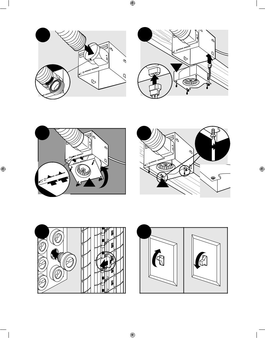
Connect 4” duct and vent to the outside. Tape joints. Connect wiring from the motor to the wiring cover plate.
If ducting does not fit securely, an adapter may need to be purchased.
A19 |
A20 |
H |
I |
Reinstall the motor by inserting the tabs and pushing up |
Secure the motor by tightening the 2 screws. |
into position. Make sure the wires are not pinched |
|
between the motor and the housing. |
|
A21 |
A22 |
|
ON |
|
OF |
|
F |
Turn on the power source.
Test the motor. If the motor does not run, check the plug connection.
41722-01 3/29/2006 |
7 |
41722_EngS_3.29.03.indd 7 |
|
|
3/29/06 10:54:51 PM |
|
|
||
|
|
|
|
A23
Go to step
E1
on page 18 to attach grille.
New Construction – suspended between joists |
|
B11 |
B12 |
|
E |
D |
|
|
5/8 |
5/8 |
|
1/2 |
||
1/2 |
||
|
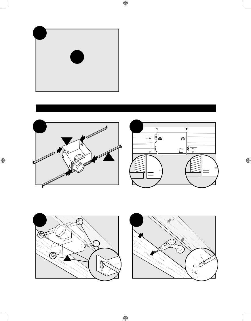
Slide the mounting rails into brackets.
Position the correct depth mark at the bottom edge of the joist based on the thickness of your sheetrock.
B13
E
Mark position of screws by using holes as a template.
8
41722_EngS_3.29.03.indd 8
B14
1/8" Bit
Drill a hole in the center of each outline.
41722-01 3/29/2006
3/29/06 10:54:53 PM
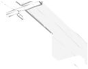
B15
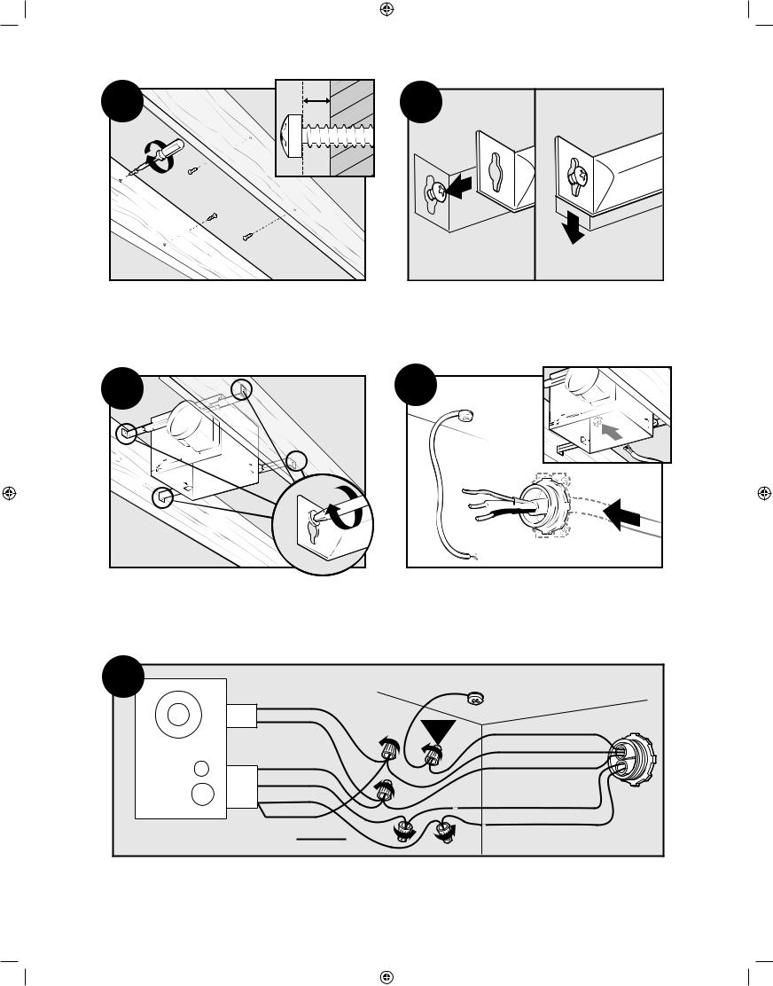
Insert screws, leaving space between the screw head and the joist. Screws are not provided.
B17
B16 |
Attach the rails onto the screws.
B18
Tighten screws. |
Pull wires through the strain relief. |
B19 |
|
|
|
Ground |
|
|
|
Black |
|
Green |
|
|
2 Pin |
|
|
A |
Bare Copper |
|
|
White |
|
||
|
|
|
|
||
Fan Motor |
|
|
|
Black |
Main Switch 1 (AC In) |
Night Light |
|
White |
|
|
White |
|
Red Night Light |
|
|
||
|
3 Pin |
|
|
||
Light |
Black |
Light |
|
|
|
|
Red |
Switch 1 (AC In) |
|||
|
|
*Option |
|||
|
|
|
|
||
*Option Fan & Main Light Together |
Black |
Switch 2 (AC In) |
|||
|
|
||||
Connect wires as shown.
41722-01 3/29/2006 |
9 |
||
41722_EngS_3.29.03.indd 9 |
|
|
3/29/06 10:54:55 PM |
|
|
||
|
|
||
|
|
|
|

B20 |
F |
|
|
|
2 |
|
1 |
|
F |
Install the wiring cover plate. Make sure all wiring connections are inside the box or under the wiring cover plate.
B21 |
G |
Tighten the wiring cover plate screw.
B22


 B23
B23
H 
|
|
|
|
Connect 4” duct and vent to the outside. Tape joints. |
Connect wiring from the motor to the wiring cover plate. |
||
If ducting does not fit securely, an adapter may need |
|
||
|
|
to be purchased. |
|
B24 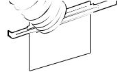
H
Reinstall the motor by inserting the tabs and pushing up into position. Make sure the wires are not pinched between the motor and the housing.
10
41722_EngS_3.29.03.indd 10
B25
 I
I
Secure the motor by tightening the 2 screws.
41722-01 3/29/2006
3/29/06 10:54:59 PM
B26 |
B27 |
|
ON |
|
OF |
|
F |
Turn on the power source.
Test the motor. If the motor does not run, check the plug connection.
B28
Go to step
E1
on page 18 to attach grille.
Existing Construction – accessible from above |
|
|
C11 |
EXISTING FAN |
NO EXISTING FAN |
OR
Remove an existing fan and check to make sure the |
Use the motor housing as a template to mark position. |
opening is large enough to accommodate the new |
|
motor housing (9”x 9.75”). |
|
41722-01 3/29/2006 |
11 |
41722_EngS_3.29.03.indd 11 |
|
|
3/29/06 10:55:02 PM |
|
|
||
|
|
|
|
|
|
|
5” |
|
|
7 |
|
9” |
. |
|
|
9 |
|
|
|
|
|
|
|
Cut out an opening for the housing.
C13 |
5/8 |
5/8 |
|
1/2 |
||
1/2 |
||
|
C12 |
E |
D |
Slide the mounting rails into brackets.
C14
Position the correct depth mark at the bottom edge of the joist based on the thickness of your sheetrock.
Mark position of screws by using holes as a template.
C15 |
C16 |
1/8" Bit
Drill a hole in the center of each outline.
Insert screws, leaving space between the screw head and the joist. Screws are not provided.
12 |
41722-01 3/29/2006 |
41722_EngS_3.29.03.indd 12 |
|
|
3/29/06 10:55:05 PM |
|
|
||
|
|
|
|
 Loading...