


Operations Manual
531369-1_F
Matrix 12
Matrix 10 |
Matrix 17 |
Matrix 20 |
Matrix 37 |
Matrix 27

Thank You!
Thank you for choosing Humminbird®, America's #1 name in fishfinders. Humminbird® has built its reputation by designing and manufacturing top-quality, thoroughly reliable marine equipment. Your Humminbird® is designed for trouble-free use in even the harshest marine environment. In the unlikely event that your Humminbird® does require repairs, we offer an exclusive Service Policy - free of charge during the first year after purchase, and available at a reasonable rate after the one-year period. For complete details, see the separate warranty card included with your unit. We encourage you to read this operations manual carefully in order to get full benefit from all the features and applications of your Humminbird® product.
Contact our Customer Resource Center at either 1-800-633-1468 or visit our website at www.humminbird.com.
WARNING! This device should not be used as a navigational aid to prevent collision, grounding, boat damage, or personal injury. When the boat is moving, water depth may change too quickly to allow time for you to react. Always operate the boat at very slow speeds if you suspect shallow water or submerged objects.
WARNING! Disassembly and repair of this electronic unit should only be performed by authorized service personnel. Any modification of the serial number or attempt to repair the original equipment or accessories by unauthorized individuals will void the warranty.
WARNING! This product contains chemicals known to the State of California to cause cancer and/or reproductive harm.
NOTE: All screens and graphics used in this manual are based on the 320V x 320H display size of the Matrix 17; however, this information is applicable to the models which have 240V x 160H, 240V x 240H and 640V x 320H displays also.
ATTENTION INTERNATIONAL CUSTOMERS: Products sold in the U.S. are not intended for use in the international market. Humminbird® international units provide international features and are designed to meet country and regional regulations. Languages, maps, time zones, units of measurement, and warranty are examples of features that are customized for Humminbird® international units purchased through our authorized international distributors.
To obtain a list of authorized international distributors, please visit our web site at www.humminbird.com or contact our Customer Resource Center at (334) 687-6613.
Humminbird®, DualBeam PLUS™, Matrix®, QuadraBeam®, SmartCast®, Selective Fish ID+®, WhiteLine™, RTS™, X-PressTM Menu, Fish ID+TM, Structure ID®, TrueArch®, UltraBlackTM, Angler Profile PresetsTM, and WeatherSenseTM are trademarked by or registered trademarks of Techsonic Industries, Inc.
© 2009 Humminbird®, Eufaula AL, USA. All rights reserved.
i

Table of Contents |
|
How Sonar Works |
1 |
Single Beam Sonar...................................................................................................................... |
2 |
DualBeam PLUS™ Sonar ............................................................................................................ |
2 |
QuadraBeam® Sonar ................................................................................................................ |
2 |
What’s On the Display |
3 |
Views |
5 |
Sonar View .................................................................................................................................. |
5 |
Understanding Sonar History .................................................................................................. |
6 |
Real Time Sonar (RTS™) Window ............................................................................................ |
7 |
Sonar Zoom View ...................................................................................................................... |
8 |
200/83 kHz Split Sonar View (DualBeam PLUS™ and QuadraBeam® Only) .................. |
9 |
Big Digits View .......................................................................................................................... |
10 |
Side Beam View (QuadraBeam® Only) .................................................................................. |
11 |
Bottom Presentation ................................................................................................................ |
12 |
Key Functions |
14 |
POWER/LIGHT Key .................................................................................................................. |
14 |
VIEW Key .................................................................................................................................. |
14 |
MENU Key .................................................................................................................................. |
15 |
4-WAY Cursor Control Key ...................................................................................................... |
15 |
EXIT Key .................................................................................................................................... |
16 |
Accessory Bus |
17 |
Powering Up the Unit |
17 |
The Menu System |
18 |
Start-Up Options Menu |
20 |
Normal Operation .................................................................................................................... |
20 |
Simulator .................................................................................................................................. |
21 |
System Status .......................................................................................................................... |
22 |
PC Connect (with PC Connect Cable Only)............................................................................ |
22 |
ii

Table of Contents |
|
Sonar X-Press™ Menu |
23 |
Sensitivity .................................................................................................................................. |
23 |
Upper Range (Advanced: Sonar, Split Sonar and Big Digits Views Only) ...................... |
24 |
Lower Range ............................................................................................................................ |
25 |
Chart Speed .............................................................................................................................. |
26 |
Bottom View ............................................................................................................................ |
26 |
Zoom Level (Sonar Zoom View Only).................................................................................... |
27 |
Sonar Menu Tab |
28 |
Beam Select (DualBeam PLUS™ and QuadraBeam® Only) .............................................. |
29 |
Fish ID+TM.................................................................................................................................... |
30 |
Fish Sensitivity .......................................................................................................................... |
31 |
Real Time Sonar (RTS™) Window .......................................................................................... |
31 |
83 kHz Sensitivity (Advanced: DualBeam PLUS™ and QuadraBeam® Only).................. |
32 |
455 kHz Balance (Advanced: QuadraBeam® Only) ............................................................ |
32 |
Depth Lines (Advanced) .......................................................................................................... |
33 |
Surface Clutter (Advanced) .................................................................................................... |
34 |
Noise Filter (Advanced)............................................................................................................ |
35 |
Max Depth (Advanced)............................................................................................................ |
35 |
Water Type (Advanced) .......................................................................................................... |
36 |
Transducer Select (QuadraBeam® Only) .............................................................................. |
36 |
Alarms Menu Tab |
37 |
Depth Alarm .............................................................................................................................. |
37 |
Fish ID Alarm ............................................................................................................................ |
37 |
Low Battery Alarm.................................................................................................................... |
38 |
Alarm Tone ................................................................................................................................ |
38 |
Setup Menu Tab |
39 |
Units - Depth ............................................................................................................................ |
40 |
Units - Temp (International Only) ........................................................................................ |
40 |
Units - Distance (with Temp/Speed or GPS Receiver) ...................................................... |
40 |
Units - Speed (with Temp/Speed or GPS Receiver) ............................................................ |
41 |
User Mode .................................................................................................................................. |
41 |
Language (International Only) .............................................................................................. |
41 |
Triplog Reset (with Temp/Speed or GPS Receiver) ............................................................ |
42 |
iii

Table of Contents |
|
Restore Defaults ...................................................................................................................... |
42 |
Select Views (Advanced) ........................................................................................................ |
43 |
Select Readouts (Advanced, Sonar View Only) .................................................................. |
44 |
Depth Offset (Advanced) ........................................................................................................ |
46 |
Temp Offset (Advanced) ........................................................................................................ |
46 |
Speed Calibration (Advanced, with Temp/Speed Only).................................................... |
47 |
NMEA Output (Advanced) ...................................................................................................... |
47 |
Accessories Menu Tab |
48 |
Troubleshooting |
49 |
Matrix Doesn’t Power Up ...................................................................................................... |
49 |
Matrix Defaults to Simulator with a Transducer Attached ............................................ |
49 |
Display Problems...................................................................................................................... |
50 |
Finding the Cause of Noise...................................................................................................... |
51 |
Matrix Fishing System Accessories |
52 |
Specifications |
53 |
Contact Humminbird |
55 |
NOTE: Entries in this Table of Contents which list (DualBeam PLUS™ and QuadraBeam® Only) are only available on products sold with a DualBeam PLUS™ or QuadraBeam® transducer.
NOTE: Entries in this Table of Contents which list (International Only) are only available on products sold outside of the U.S. by our authorized international distributors. To obtain a list of authorized international distributors, please visit our web site at www.humminbird.com or contact our Customer Resource Center at (334) 687-6613.
NOTE: Entries in this Table of Contents which list (with Temp/Speed or GPS Receiver, or (with PC Connect Cable Only) require the purchase of separate accessories. You can visit our web site at www.humminbird.com to order these accessories online or contact our Customer Resource Center at 1-800-633-1468.
iv

How Sonar Works
Sonar technology is based on sound waves. The Matrix Fishing System uses sonar to locate and define structure, bottom contour and composition, as well as depth directly below the transducer.
Your Matrix Fishing System sends a sound wave signal and determines distance by measuring the time between the transmission of the sound wave and when the sound wave is reflected off of an object; it then uses the reflected signal to interpret location, size, and composition of an object.
Sonar is very fast. A sound wave can travel from the surface to a depth of 240 ft (70 m) and back again in less than ¹⁄ of a second. It is unlikely that your boat can "outrun" this sonar signal.
Your Matrix Fishing System will either have Single Beam, DualBeam PLUS™ or QuadraBeam™ sonar. Find the correct sonar description that applies to your unit.
1
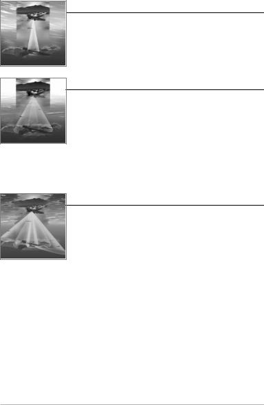
Single Beam Sonar
Your Matrix 10, 12 or 20 uses a 200 kHz single beam sonar system with a 20° area of coverage. Depth capability is affected by such factors as boat speed, wave action, bottom hardness, water conditions and transducer installation.
DualBeam PLUS™ Sonar
Your Matrix 17 or 27 uses a 200/83 kHz DualBeam PLUS™ sonar system with a wide (60°) area of coverage. DualBeam PLUS™ sonar returns can be blended together, viewed separately or compared side-by-side. DualBeam PLUS™ is ideal for a wide range of conditions - from shallow to very deep water in both fresh and salt water. Depth capability is affected by such factors as boat speed, wave action, bottom hardness, water conditions and transducer installation.
QuadraBeam™ Sonar
Your Matrix 37 Fishing System uses QuadraBeam® sonar. QuadraBeam® sonar provides an extremely wide 90° area of coverage. QuadraBeam® starts with two 45° 455 kHz beams for a continuous 90° of uninterrupted side to side coverage to 160 feet. These Side Structure locating beams reveal fish and structure to the left and right of your boat near the bottom. For structure directly below your boat, QuadraBeam® uses DualBeamPLUS™ technology.
2

What’s On the Display
The Matrix Fishing System can display a variety of useful information about the area
Depth - water depth; can be set to alarm when the water becomes too shallow.
Speed - if a Temp/Speed accessory or GPS Receiver is attached, the Matrix can display the speed of the boat, and can keep a Triplog of nautical or statute miles traveled.
Temperature - water surface temperature.
Timer - elapsed time with Temp/Speed Accessory or GPS Receiver.
Distance - distance traveled with Temp/Speed Accessory or GPS Receiver.
Average Speed - average speed reading with Temp/Speed Accessory or GPS Receiver.
Cursor - available in Freeze Frame and can depth of a sonar return and bottom depth
Bait Ball
Hard Bottom
Rocky Bottom
Second Sonar Return - when the sonar signal bounces between the bottom and the surface of the water and back again. Use the appearance of the second return to determine bottom hardness. Hard bottoms will show a strong second return, while soft bottoms will show a very weak one or none at all.
Cursor Dialog Box - indicates cursor depth directly below the cursor.
NOTE: Entries in this view that list (with Temp/Speed or GPS Receiver) are available if either information from the GPS receiver will be displayed on the view.
3
under and adjacent to your boat, including the following items:
be positioned in the Sonar View to provide below the cursor.
on the display and the depth of the bottom
83 kHz, Wide Beam Hollow Fish Symbol (DualBeam PLUS™ Units Only)
Structure - where fish may be hiding.
Fish - fish are displayed as arches and/or fish icons, and the unit can be set to alarm when a fish of a certain size is detected. When a target is detected and Fish ID+ is on, a Fish ID+TM symbol with depth is displayed. The size of the symbol shows the intensity of the sonar return. The unit will clearly show schools of Bait Fish as "clouds" of different shapes and sizes, depending on the number of fish and boat speed.
200 kHz, Narrow Beam Shaded Fish Symbol
Thermoclines - layers of water with different temperatures that appear at different depths and different times of the year. A thermocline typically appears as a continuous band of many gray levels moving across the display at the same depth.
Soft Bottom
RTS™ (Real Time Sonar) Window
Battery Voltage - the voltage of the boat’s battery; can be set to alarm if the voltage falls below a certain point.
device is connected to the Matrix Fishing System. If both devices are connected, then only the
4

Views
The views available on your Matrix Fishing System are:
•Sonar View
•Zoom View
•200/83 kHz Split Sonar View (DualBeam PLUS™ and QuadraBeam® Only)
•Big Digits View
•Side Beam View (QuadraBeam® Only).
Sonar View is the default view. When the VIEW key is pressed, the display cycles through the available views. When the EXIT key is pressed, the display cycles through the available views in reverse order. Any view can be hidden or displayed as part of the view rotation using Select View from the Advanced Setup Menu.
NOTE: When you change any menu settings that affect the sonar, the view will update immediately (i.e. you don’t have to exit the menu to apply the change to the screen). For instance, by switching between "Inverse" and "Structure ID®" from the X-PressTM Menu it is possible to quickly alternate between the two viewing methods.
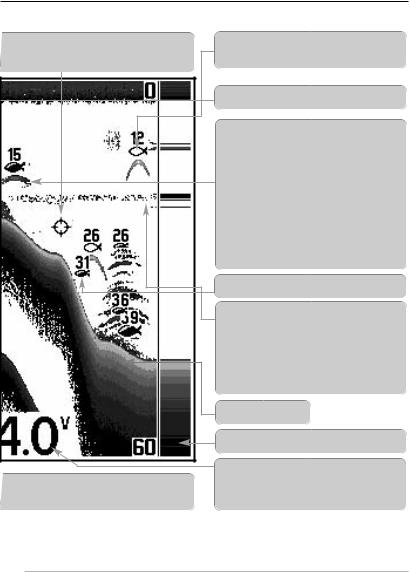
Sonar View
Sonar View presents a historical log of sonar returns. Depth is always displayed. Readouts for temperature and speed are automatically displayed if the appropriate accessory is connected. The most recent sonar returns are charted on the right side of the window; as new information is received, the older information is moved across the display to the left. A Digital Depth Readout is displayed in the upper left corner. A scale with Upper and Lower Depth Range readouts appears along the right edge of the Sonar View. The scale indicates the distance from the surface of the water to a depth range sufficient to show the bottom. Depth Range is automatically selected to keep the bottom visible on the display, although you can adjust it manually as well (see Sonar X-PressTM Menu). Either five or six additional Digital Readouts (depending on your model) display information from optional-purchase accessories. These information boxes can be customized to show only the information desired (see Setup Menu Tab, Select Readouts).
5
Sonar View
Depth |
|
|
|
|
|
|
|
Upper Depth |
|
|
|
|
|
|
|||
|
|
|
|
|
|
|
Range |
|
|
|
|
|
|
|
|
|
|
Temperature |
|
|
|
|
|
|
|
RTS™ Window |
|
|
|
|
|
|
|
||
|
|
|
|
|
|
|
||
|
|
|
|
|
|
|
|
|
Triplog |
|
|
|
|
|
|
|
Cursor |
|
|
|
|
|
|
|
||
Sonar History |
|
|
|
|
|
|
|
|
|
|
|
|
|
|
|
||
|
|
|
|
|
|
|
|
|
|
|
|
|
|
|
|
|
|
Window |
|
|
|
|
|
|
|
|
Cursor Dialog Box
Lower Depth
Range
NOTE: If the Depth number is flashing, it means that the unit is having trouble locating the bottom. This usually happens if the water is too deep, the transducer is out of the water, the boat is moving too fast, or for any other reason that the unit can’t accurately receive continuous data.
Freeze Frame - Pressing any arrow on the 4-WAY Cursor Control key will freeze the screen in the Sonar View and a cursor will be displayed on the screen. The cursor can be positioned on the display using the 4-WAY Cursor Control key to determine the depth of any sonar return. The RTS™ Window continues to update in Freeze Frame. In addition, see the effects of menu setting changes with Instant Image Update. Pressing EXIT will exit Freeze Frame and the display will start to scroll. Freeze Frame is only available in the Sonar View.
Understanding Sonar History
It is important to understand the significance of the Matrix Fishing System display. The display does NOT show a literal 3-dimensional representation of what is under the water. Each vertical band of data received by the control head and plotted on the display represents something that was detected by a sonar return at a particular time. As both the boat and the targets (fish) may be moving, the returns are only showing a particular segment of time when objects were detected, not exactly where those objects are in relation to other objects shown on the display.
6
Real Time Sonar (RTS™) Window
A Real Time Sonar (RTS™) Window appears on the right side of the display in the Sonar View only. The RTS™ Window always updates at the fastest rate possible for depth conditions and shows only the returns from the bottom, structure and fish that are within the transducer beam. The RTS™ Window plots the depth and intensity of a sonar return (see Sonar Menu - RTS™ Window).
The Narrow RTS™ Window indicates the sonar intensity through the use of grayscale. The grayscale used matches the bottom view grayscale setting used in the sonar history window (i.e. Inverse, StructureID®, WhiteLine™, Bottom Black). The depth of the sonar return is indicated by the vertical placement of the return on the display depth scale.
The Wide RTS™ Window indicates the sonar intensity through the use of a bar graph. The length of the plotted return provides an indication of whether the return is weak or strong. The depth of the sonar return is indicated by the vertical placement of the return on the display depth scale. The Wide RTS™ Window does not make use of grayscale.
7
Sonar Zoom View
Sonar Zoom View increases the displayed resolution to separate sonar returns that are very close together, such as those caused by fish suspended close to the bottom or within structure. In Zoom View, the display is split to show a narrow slice of the full range view on the right and the zoomed view on the left. The full range view on the right also contains the Zoom Preview Box that shows what part of the full range view is shown in zoom view on the left; the Zoom Preview Box tracks the bottom in the full range view.
As the depth changes, the zoomed view updates automatically to display a magnified image of the bottom. The Zoom Preview Box shows where the zoomed view is in relation to the full range view. The Zoom Level, or magnification, is displayed in the lower left corner and can be changed to suit conditions (see Sonar X-PressTM Menu: Zoom Level). Upper and Lower Zoom Depth Range numbers indicate the depth of the water which is being viewed.
Digital depth is displayed in the upper left hand corner. The digital readouts in the Sonar Zoom View cannot be customized; therefore, information such as water temperature and voltage are unavailable in the Sonar Zoom View.
|
|
|
|
|
Sonar Zoom View |
||||
|
|
|
|
|
|
|
|
|
Upper Depth Range, |
|
|
|
|
|
|
|
|
|
|
Depth |
|
|
|
|
|
|
|
|
Full Range View |
|
|
|
|||||||
|
|
|
|
|
|
|
|
|
Upper Depth Range, |
|
|
|
|
|
|
|
|
|
Zoom View |
|
|
|
|
|
|
|
|
|
Full Range View |
|
|
|
|
|
|
|
|
|
|
|
|
|
|
|
|
|
|
|
Zoom |
|
|
|
|
|
|
|
|
|
|
|
|
|
|
|
|
|
|
|
Preview Box |
Zoomed |
|
|
|
|
|
|
|
|
|
|
|
|
|
|
|
|
|
|
|
View |
|
|
|
|
|
|
|||
Zoom Level |
|
|
|
|
|
|
|
Lower Depth Range, |
|
|
|
|
|
|
|
|
|||
|
|
|
|
|
|
|
|
|
Full Range View |
|
|
|
|
|
Lower Depth |
||||
|
|
|
|
|
Range, Zoom View |
||||
8
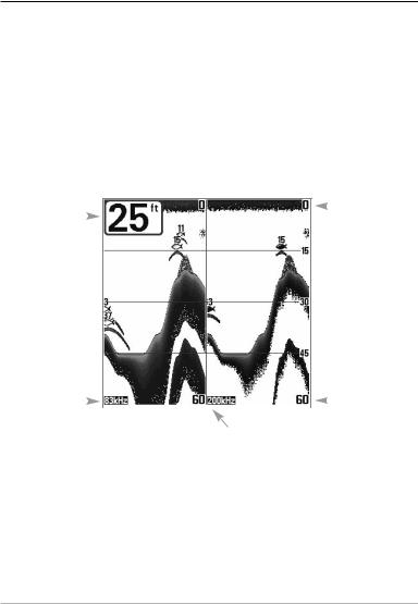
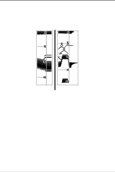
200/83 kHz Split Sonar View
(DualBeam PLUS™ and QuadraBeam® Only)
Split Sonar View displays sonar returns from the 83 kHz wide beam on the left side of the screen and displays sonar returns from the 200 kHz narrow beam on the right side of the screen. Depth is always displayed in the upper left hand corner. You can use the Split Sonar View to make side by side comparisons between the sonar returns from the 83 kHz wide beam and the 200 kHz narrow beam.
The digital readouts in the Split Sonar View cannot be customized; therefore, information such as water temperature and voltage are unavailable in the Split Sonar View.
200/83 kHz Split Sonar View
Depth |
|
|
|
Upper |
|
|
|
||
|
|
|
Depth Range |
|
|
|
|
||
|
|
|
|
83 kHz |
|
|
|
|
||
Sonar History |
|
|
|
|
|
Lower |
|
|
|
|
|
||
Window |
|
|
|
Depth Range |
||
|
|
|
200 kHz |
|||
|
|
|
Sonar History Window |
|||
9
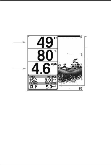
Big Digits View
Big Digits View provides digital data in a large, easy-to-see format. Depth is always displayed. Readouts for temperature, speed and Triplog information are displayed automatically if the appropriate accessory is connected to the system. The Triplog shows distance traveled, average speed, and time elapsed since the Triplog was last reset. The digital readouts in the Big Digits View cannot be customized.
Big Digits View
Depth
Temperature 
Speed
Timer shows the time elapsed since Triplog was last reset
Distance is the distance traveled since the Triplog was last reset
Voltage - the battery voltage.
Average Speed shows the speed since the Triplog was last reset
10
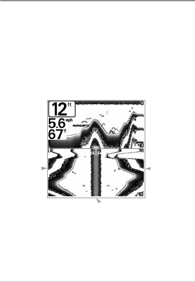
Side Beam View
(QuadraBeam® Only)
Side Beam View shows sonar information from both the left and right 90° 455 kHz beams and the 200 kHz down-looking beam in one view. The top portion of the display presents a historical log of sonar returns from the 200 kHz down-looking sonar. The bottom portion of the display presents a historical log of sonar returns from the 455 kHz rightand left-looking sonar. New information appears at the top, and scrolls down the display in the 455 kHz Windows. The sonar information from the side-looking beams reveal bottom contour, structure and fish similar to the down-looking beam, but the area covered is to the left and right of the area shown in the down-looking portion so you actually see more of the bottom. The distance covered by the right and left 90° beams is based on the depth setting for the down-looking beam, up to a maximum of 160 feet.
Side Beam View
Depth 
 200 kHz Sonar
History Window
Temperature 
Left Side 455 kHz |
|
|
|
Right Side 455 kHz |
|
|
|
||
Sonar History |
|
|
|
Sonar History |
Window |
|
|
|
Window |
 Water Surface Line for 455 kHz
Sonar History Windows
The digital readouts in the Side Beam View cannot be customized.
11
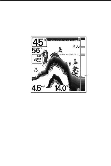
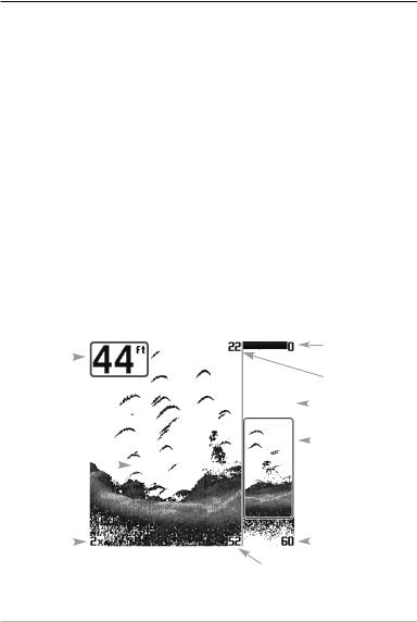
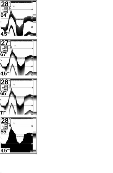
Bottom Presentation
As the boat moves, the unit charts the changes in depth on the display to create a profile of the Bottom Contour. The type of bottom can be determined from the return charted on the display. A Hard Bottom such as compacted sediment or flat rock appears as a thinner line across the display. A Soft Bottom such as mud or sand appears as a thicker line across the display. Rocky Bottoms have a broken, random appearance.
Bottom Contour Profile with RTS™ Window.
Temp/Speed Accessory is optional.
Hard Bottom
Soft Bottom
Rocky Bottom 
The sonar returns from the bottom, structure and fish can be represented as either
Inverse (default), WhiteLine™, Structure ID®, or Bottom Black. See Sonar X-PressTM
Menu: Bottom View for details on how to set the bottom view.
12
Inverse is a method where weak returns are shown with dark pixels and strong returns with lighter pixels. This has the benefit of ensuring that weak signals will be clearly visible on the display.
Structure ID® represents weak returns as light pixels and strong returns as dark pixels. This has the benefit of ensuring that strong returns will be clearly visible on the display.
WhiteLine™ highlights the strongest sonar returns in white, resulting in a distinctive outline. This has the benefit of clearly defining the bottom on the display.
Bottom Black displays all pixels below the bottom contour as black, regardless of signal strength. This has the benefit of providing a high contrast between the bottom and other sonar returns on the display. Any targets such as fish, structure and thermoclines will be shown using the Structure ID® method.
13
 Loading...