


 Loading...
587ci and 597ci Combo
Operations Manual
531696-1_A

Thank You!
Thank you for choosing Humminbird®, America's #1 name in fishfinders. Humminbird® has built its reputation by designing and manufacturing top-quality, thoroughly reliable marine equipment. Your Humminbird® is designed for trouble-free use in even the harshest marine environment. In the unlikely event that your Humminbird® does require repairs, we offer an exclusive Service Policy - free of charge during the first year after purchase, and available at a reasonable rate after the one-year period. For complete details, see the separate warranty card included with your unit. We encourage you to read this operations manual carefully in order to get full benefit from all the features and applications of your Humminbird® product.
Contact our Customer Resource Center at either 1-800-633-1468 or visit our web site at www.humminbird.com.
WARNING! This device should not be used as a navigational aid to prevent collision, grounding, boat damage, or personal injury. When the boat is moving, water depth may change too quickly to allow time for you to react. Always operate the boat at very slow speeds if you suspect shallow water or submerged objects.
WARNING! Disassembly and repair of this electronic unit should only be performed by authorized service personnel. Any modification of the serial number or attempt to repairthe original equipment or accessories by unauthorized individualswill void the warranty.
WARNING! This product contains chemicals known to the State of California to cause cancer and/or reproductive harm.
NOTE: Some features discussed in this manual require a separate purchase, and some featuresare only available on international models. Every efforthas been made to clearly identify those features. Please read the manual carefully in order to understand the full capabilities of your model.
ENVIRONMENTAL COMPLIANCE STATEMENT: It is the intentionof Humminbird®to be a responsible corporate citizen, operating in compliance with known and applicable environmentalregulations, and a good neighbor in the communitieswhere we make or sell our products.
WEEE DIRECTIVE: EU Directive 2002/96/EC “Wasteof Electricaland ElectronicEquipment Directive (WEEE)” impacts most distributors, sellers, and manufacturers of consumer electronics in the European Union. The WEEE Directiverequires the producer of consumer electronics to take responsibility for the management of waste from their products to achieve environmentally responsible disposal during the product life cycle.

WEEE compliance may not be required in your locationfor electrical & electronicequipment (EEE), nor may it be required for EEE designed and intended as fixed or temporary installation in transportation vehicles such as automobiles, aircraft, and boats. In some European Union member states, these vehicles are consideredoutside of the scope of the Directive, and EEE for those applications can be considered excluded from the WEEE Directive requirement.
This symbol (WEEE wheelie bin) on product indicates the product must not be disposed of with other household refuse. It must be disposed of and collectedfor recycling and recovery of waste EEE. Humminbird® will mark all EEE products in accordance with the WEEE Directive. It is our goal to comply in the collection, treatment, recovery, and environmentally sound disposalof those products;however, these requirement do vary within European Union member states. For more information about where you should dispose of your waste equipment for recyclingand recovery and/or your European Union member state requirements, please contact your dealer or distributorfrom
which your product was purchased.
ROHS STATEMENT: Product designed and intended as a fixed installation or part of a system in a vessel may be considered beyond the scope of Directive 2002/95/EC of the European Parliament and of the Council of 27 January 2003 on the restriction of the use of certain hazardous substances in electrical and electronicequipment.
Navionics® Gold, HotMaps™, and HotMaps Premium™ are registered trademarks of Navionics®. 500 Series™, Fish ID+™, FishingGPS®, Humminbird®, RTS™, RTS Window™, Structure ID®, Selective Fish ID+®, WhiteLine™, UniMap™, and X-Press™ Menu are trademarked by or registered trademarks of Humminbird®.
© 2008 Humminbird®, Eufaula AL, USA. All rights reserved.

Table of Contents |
|
How Sonar Works |
1 |
DualBeam Sonar ...................................... |
................................................................ 3 |
How GPS and Cartography Work |
4 |
What’s On the Sonar Display |
6 |
Understanding the Sonar Display ............................................................................ |
8 |
Real Time Sonar (RTS™) Window ............................................................................ |
9 |
Freeze Frame and Active Cursor............................................................................. |
10 |
Bottom Presentation.............................................................................................. |
11 |
Views |
13 |
Sonar View ............................................................................................................ |
16 |
Sonar Zoom View .................................................................................................. |
17 |
Big Digits View ...................................................................................................... |
18 |
Bird's Eye View ...................................................................................................... |
19 |
Chart View.............................................................................................................. |
20 |
Chart/Sonar Combo View........................................................................................ |
22 |
View Orientation.................................................................................................... |
23 |
Viewing Cartography ............................................................................................ |
23 |
Introduction to Navigation |
26 |
Waypoints, Routes, and Tracks ............................................................................. |
27 |
Save, Edit, or Delete a Waypoint ........................................................................... |
28 |
Navigate to a Waypoint or Position ........................................................................ |
30 |
Add a Waypoint Targetor Trolling Grid .................................................................. |
31 |
Save, Edit, or Delete a Route ................................................................................. |
33 |
Save or Clear a Current Track................................................................................. |
34 |
Edit, Delete, or Hide Saved Tracks ......................................................................... |
34 |
i

Table of Contents |
|
Using Your 500 Series™ Control Head |
36 |
Key Functions |
37 |
POWER/LIGHT Key ............................................................................................. |
37 |
VIEW Key ............................................................................................................. |
37 |
INFO Key ............................................................................................................... |
38 |
MENU Key ........................................................................................................... |
38 |
4-WAY Cursor Control Key ................................................................................. |
39 |
MARK Key............................................................................................................. |
40 |
GOTO Key............................................................................................................... |
40 |
ZOOM (+/-) Key..................................................................................................... |
40 |
EXIT Key ............................................................................................................... |
41 |
Multi-Media Card (MMC)/SD Slot |
42 |
Adding Maps to Your Fishfinder .......................................................................... |
42 |
Exporting Navigation Data ................................................................................... |
43 |
Powering On the Unit |
44 |
The Menu System |
45 |
Start-Up Options Menu |
46 |
Normal Operation ................................................................................................. |
47 |
Simulator ............................................................................................................. |
47 |
System Status ..................................................................................................... |
49 |
Self Test................................................................................................................. |
49 |
Accessory Test....................................................................................................... |
50 |
GPS Diagnostic View ........................................................................................... |
51 |
X-Press™ Menu |
52 |
ii

Table of Contents |
|
Main Menu |
53 |
Quick Tips for the Main Menu .................................................................................... |
54 |
User Mode (Normal or Advanced) .............................................................................. |
55 |
Sonar X-Press™ Menu (Sonar views only) |
57 |
Sensitivity ................................................................................................................ |
58 |
Upper Range (Advanced: Sonar and Big Digitsviewsonly).............................................. |
59 |
Lower Range .......................................................................................................... |
60 |
Chart Speed ............................................................................................................ |
61 |
Cancel Navigation (only when Navigating) ................................................................ |
61 |
Navigation X-Press™ Menu (Navigation views only) |
62 |
Waypoint [Name] (Only with an active cursor on a waypoint) ...................................... |
63 |
Cursor To Waypoint (Chart or Combo View only) ........................................................ |
64 |
Save Current Track .................................................................................................. |
64 |
Clear Current Track .................................................................................................. |
65 |
Save Current Route (only when Navigating) .............................................................. |
65 |
Skip Next Waypoint (only when Navigating) .............................................................. |
66 |
Cancel Navigation (only when Navigating) ................................................................ |
66 |
Remove Target (only if Target is Active) ...................................................................... |
67 |
Remove Grid (only if Grid is Active).............................................................................. |
67 |
Sonar Window (Combo View only).............................................................................. |
67 |
Waypoint [Name] (Most recently-created waypoint) .................................................... |
68 |
Alarms Menu Tab |
69 |
Depth Alarm ............................................................................................................ |
70 |
Fish ID Alarm............................................................................................................ |
70 |
Low Battery Alarm .................................................................................................. |
71 |
Temp. Alarm ............................................................................................................ |
71 |
Off Course Alarm...................................................................................................... |
72 |
Arrival Alarm ............................................................................................................ |
72 |
Drift Alarm................................................................................................................ |
73 |
Alarm Tone .............................................................................................................. |
74 |
iii

Table of Contents |
|
Sonar Menu Tab |
75 |
Fish ID+™ ............................................................................................................. |
76 |
Fish ID Sensitivity ................................................................................................. |
77 |
Real Time Sonar (RTS™) Window ........................................................................ |
77 |
Bottom View ......................................................................................................... |
78 |
Zoom Width ......................................................................................................... |
78 |
Depth Lines (Advanced) .......................................................................................... |
79 |
Surface Clutter (Advanced)...................................................................................... |
80 |
Noise Filter (Advanced) ............................................................................................ |
81 |
Max Depth (Advanced) ............................................................................................ |
81 |
Water Type (Advanced) ............................................................................................ |
82 |
Navigation Menu Tab |
83 |
Current Track......................................................................................................... |
84 |
Saved Tracks ......................................................................................................... |
84 |
Waypoints ............................................................................................................. |
86 |
Routes ................................................................................................................... |
88 |
Chart Orientation ................................................................................................. |
89 |
Chart Detail Level ................................................................................................. |
90 |
Map Borders ......................................................................................................... |
91 |
Lat/Lon Grid........................................................................................................... |
91 |
Spot Soundings ...................................................................................................... |
92 |
Shaded Depth ....................................................................................................... |
92 |
Chart Select........................................................................................................... |
92 |
North Reference ................................................................................................... |
93 |
Waypoint Decluttering (Advanced).......................................................................... |
93 |
Grid Rotation ......................................................................................................... |
94 |
Trackpoint Interval ............................................................................................... |
94 |
Track Min Distance(Advanced) .............................................................................. |
95 |
iv

Table of Contents |
|
Map Datum (Advanced) ............................................................................................ |
95 |
Set Simulation Position (Advanced) .......................................................................... |
96 |
Set Map Offset (Advanced)........................................................................................ |
97 |
Course Projection Line ........................................................................................... |
97 |
Clear Map Offset (Advanced) .................................................................................... |
98 |
Export All Nav Data (Advanced) ................................................................................ |
98 |
Delete All Nav Data (Advanced) ................................................................................ |
99 |
Setup Menu Tab |
100 |
Units - Depth.......................................................................................................... |
101 |
Units - Temp (International only) .............................................................................. |
101 |
Units - Distance...................................................................................................... |
101 |
Units - Speed.......................................................................................................... |
102 |
User Mode ............................................................................................................ |
102 |
Language (International only).................................................................................... |
102 |
Triplog Reset ......................................................................................................... |
103 |
Restore Defaults ................................................................................................... |
103 |
Select Readouts (Advanced, Sonar View only) .......................................................... |
104 |
Depth Offset (Advanced).......................................................................................... |
105 |
Temp. Offset (Advanced, with Temp/Speed only) ........................................................ |
106 |
Speed Calibration (Advanced, with Temp/Speed only)................................................ |
106 |
Local Time Zone (Advanced) .................................................................................... |
107 |
Daylight Saving Time (Advanced)............................................................................ |
107 |
Position Format (Advanced) .................................................................................... |
108 |
Time Format (Advanced, International only)................................................................ |
108 |
Date Format (Advanced, International only)................................................................ |
109 |
NMEA Output (Advanced) ...................................................................................... |
109 |
Sonar .................................................................................................................... |
110 |
v

Table of Contents |
|
Views Menu Tab |
111 |
Troubleshooting |
112 |
Fishfinder Doesn’t Power Up .............................................................................. |
112 |
Fishfinder Defaults to Simulator with a Transducer Attached.......................... |
112 |
Display Problems ............................................................................................... |
113 |
Finding the Cause of Noise ............................................................................... |
114 |
500 Series™ Fishfinder Accessories |
115 |
Specifications |
116 |
Glossary |
117 |
Contact Humminbird® |
133 |
NOTE: Entries in this Table of Contents which list (International Only) are only available on products sold outside of the U.S. by our authorized International Distributors. It is important to note that products sold in the U.S. are not intended for resale in the international market. To obtain a list of authorized International Distributors, please visit our website at www.humminbird.com or contact our Customer Resource Center at 1-800-633-1468 to locate the distributornearest you.
NOTE: Entries in this Table of Contents which list (with Temp/Speed only) require the purchase of separate accessories. You can visit our website at www.humminbird.com to order these accessories online or contact our Customer Resource Center at 1-800-633-1468.
NOTE: Some features discussed in this manual require a separate purchase, and some features are only available on international models. Every effort has been made to clearly identify those features. Please read the manual carefully in order to understand the full capabilities of your model.
vi
How Sonar Works
Sonar technology is based on sound waves. The 500 Series™ Fishfinder uses sonar to locate and define structure, bottom contour and composition, as well as depth directly below the transducer.
Your 500 Series™ Fishfinder sends a sound wave signal and determines distance by measuring the time between the transmission of the sound wave and when the sound wave is reflected off of an object; it then uses the reflected signal to interpret location, size, and composition of an object.
Sonar is very fast. A sound wave can travel from the surface to a depth of 240 ft (70 m) and back again in less than 1/4 of a second. It is unlikely that your boat can “outrun“ this sonar signal.
SONAR is an acronym for SOund and NAvigation Ranging. Sonar utilizes precision sound pulses or “pings“ which are emitted into the water in a teardrop-shaped beam.
The sound pulses “echo“ back from objects in the water such as the bottom, fish, and other submerged objects. The returne d echoes are displayed on the LCD screen. Each time a new echo is received, the old echoes are moved across the LCD, creating a scrolling effect.
1 |
How Sonar Works |
When all the echoes are viewed side by side, an easy to interpret “graph“ of the bottom, fish, and structure appears.
The sound pulses are transmitted at various frequencies depending on the application. Very high frequencies (455 kHz) are used for greatest definition but the operating depth is limited. High frequencies (200 kHz) are commonly used on consumer sonar and provide a good balance between depth performance and resolution. Low frequencies (83 kHz) are typically used to achieve greater depth capability.
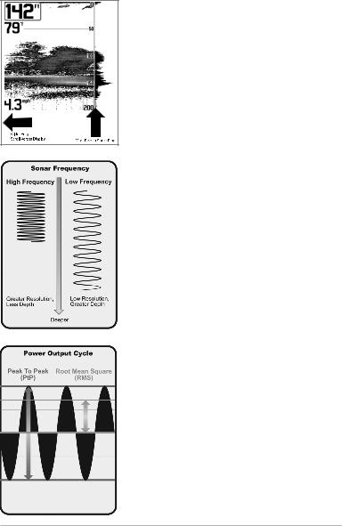
The power output is the amount of energy generated by the sonar transmitter. It is commonly measured using two methods:
•Root Mean Square (RMS) measures power output over the entire transmit cycle.
•Peak to Peak measures power output at the highest points.
The benefits of increased power output are the ability to detect smaller targets at greater distances, ability to overcome noise, better high speed performance, and enhanced depth capability.
How Sonar Works |
2 |
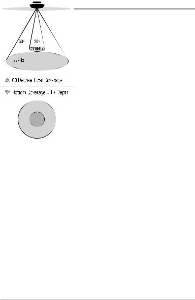
DualBeam Sonar
Your 500 Series™ Fishfinder uses a 200/83 kHz DualBeam sonar system with a wide (60°) area of coverage. DualBeam sonar is optimized to show the greatest bottom definition using a narrow (20°) beam yet can still indicate fish found in the wide (60°) beam when the Fish ID+™ feature is turned on. DualBeam is ideal for a wide range of conditions - from shallow to very deep water in both fresh and salt water. Depth capability is affected by such factors as boat speed, wave action, bottom hardness, water conditions, and transducer installation.
3 |
How Sonar Works |

How GPS and Cartography Work
Your 500 Series™ Fishfinder also supports GPS and chartplotting. It uses GPS and sonar to determine your position, display it on a grid, and provide detailed underwater information. The Global Positioning System (GPS) is a satellite navigation system designed and maintained by the U.S. Department of Defense. GPS was originally intended for military use; however, civilians may also take advantage of its highly accurate position capabilities, typically within +/- 10 meters, depending on conditions. This means that 95% of the time, the GPS receiver will read a location within 10 meters of your actual position. Your GPS Receiver also uses information from WAAS (the Wide Area Augmentation
System), EGNOS (the European Geostationary Navigation Overlay Service), and MSAS (the MTSAT Satellite Augmentation System) satellites if they are available in your area.
GPS uses a constellation of 24 satellites that continually send radio signals to the earth. Your present position is determined by receiving signals from up to 16 satellites and measuring the distance from the satellites.
All satellites broadcast a uniquely coded signal once per second at exactly the same time. The GPS receiver on your boat receives signals from satellites that are visible to it. Based on time
differences between each received signal, the GPS receiver determines its distance to each satellite. With distances known, the GPS receiver mathematically triangulates its own position. With once per second updates, the GPS receiver then calculates its velocity and bearing.
How GPS and Cartography Work |
4 |

The GPS Receiver included with your 500 Series™ Fishfinder allows you to combine easy-to-use FishingGPS® chartplotter and navigation capabilities with advanced fishfinding.
The following GPS functionality is currently supported by the 500 Series™ Fishfinder when it is connected to the included GPS receiver:
•View current position
•View current track (breadcrumb trail)
•View precision speed and heading from your GPS receiver
•Save tracks, waypoints, and routes
•Travel a route and navigate from one waypoint to the next.
Your 500 Series™ supports Navionics® Gold, HotMaps™ and HotMaps™
Premium on MMC or SD card media. You can insert optional-purchase cards in the (MMC)/SD slot on your control head to access additional detailed maps. See Multi-Media Card (MMC)/SD Slot for more information.
NOTE: Your 500 Series™ supports Navionics® Gold, HotMaps™, and HotMaps™ Premium. Your 500 Series™ does not support Navionics® Classic Charts or Platinum™ Cartography.
Your unit also comes with a built-in UniMap™ with a more detailed map of North America (Domestic models) or a more detailed map of Europe and Southeast Asia, including Australia and New Zealand (International models).
Your 500 Series™ uses the GPS Receiver to determine the position of the boat automatically, and it uses the zoom level settings on a particular view to select the best chart to display. See Chart View: Viewing Cartography for more information.
5 |
How GPS and Cartography Work |

What’s On the Sonar Display
The 500 Series™ Fishfinder can display a variety of useful information about the
Depth - water depth; can be set to alarm when the water becomestoo shallow.
Temperature - water surface temperature.
Timer - Elapsed time with Temp/Speed
Accessory or GPS Receiver.
Distance - Distance traveled with Temp/Speed
Accessory or GPS Receiver.
Average Speed - Average speed reading with
Temp/Speed Accessory or GPS Receiver.
Speed - if a Temp/Speed accessory or GPS Receiver is attached, the Fishfinder can display the speed of the boat and can keep a Triplog of nautical or statutemiles traveled.
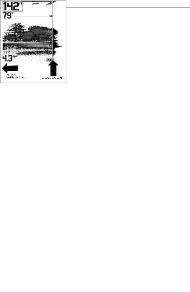
Second Sonar Return - when the sonar signal bouncesbetweenthebottomand thesurface ofthe water and backagain. Use the appearance of the second returnto determine bottomhardness. Hard bottomswillshowa strongsecondreturn,whilesoft bottomswillshowa veryweakone ornoneat all.
Cursor Dialog Box - indicates cursor depth on the display and the depth of the bottom directly below the cursor. The Latitude and Longitude of the cursor position, the distance to travel to the cursor position and the bearing to the cursor position is shown with a GPS receiver. A waypoint can be marked at the cursor position for later retrieval and use with a GPS receiver.
NOTE: Entriesin this view that list (with Temp/Speedor GPS Receiver)are availableif either device informationfrom the GPS receiverwill be displayedon the view.
What’s On the Sonar Display |
6 |
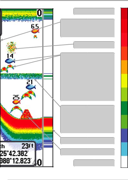
area under and adjacent to your boat, including the following items:
High Sonar Intensity Return 
Cursor - available in Freeze Frame and can be positioned in the Sonar View to provide depth of a sonar return and bottomdepthbelow the cursor.
Bait Ball
Fish - the Fishfinder displays fish as arches and/or fish icons, and can be set to alarm when a fish of a certain size is detected. When a target is detected, a Fish ID+™ symbol appears on the display with the depth displayed above it. The size of the symbol indicates the intensity of the sonar return. The unit will clearly show schools of Bait Fish as "clouds" of different shapes and sizes, depending on the number of fish and boat speed.
Thermoclines - layers of water with different temperatures that appear at different depths and differenttimes of the year. A thermocline typically appears as a continuous band of many colors moving across the display at the same depth.
RTS (Real Time Sonar) Window™
Structure - where fish may be hiding.
Low Sonar Intensity Return 
is connected to the 500 Series™ Fishfinder.If both devices are connected,then only the
7 |
What’s On the Sonar Display |
The returned s onar echoes are di splayed on the screen. As a new echo is received, the historicaldata scrolls across the screen.
Understanding the Sonar Display
It is im portant to u nderstand th e sign ificance of the display. The display does not show a literal 3- dimensional re presentation o f what is under the water. Each vertical band of dat a received by the control head and plotted on the display represents something that was detected by a sonar return at a particular time. As both the boat and the targets (fish) may be moving, the returns are only showing a pa rticular s egment of tim e w hen o bjects were detected, no t exactly wh ere those o bjects are in relation to other objects shown on the display.
What’s On the Sonar Display |
8 |
Real Time Sonar (RTS™) Window
A Real Time Sonar (RTS™) Window appears on the right side of the display in the Sonar View only. The RTS Window™ updates at the fastest rate possible for depth conditions and shows only the returns from the bottom, structure, and fish that are within the transducer beam . The RTS Wind ow™ plots the depth and intensity of a sonar return (see Sonar Menu Tab: RTS Window™).
The Narrow RTS W indow™ indicates the sonar intensity through the use of colors. Red indicates a strong return and blue indicates a weak return. The depth of the sonar return is indicated by t he ver tical placement of the return on the display depth scale.
The Wide R TS Window™ indicates t he so nar i ntensity through the u se of a ba r graph. The length of the plotted r eturn indicates whether the return is weakor strong. The depth of the sonar return is in dicated by th e vertical p lacement of th e return o n the d isplay d epth
scale. The Wide RT |
S |
Window™ does n ot us |
e |
grayscale. |
|
9 |
What’s On the Sonar Display |

Freeze Frame and Active Cursor
Freeze Frame & Active Cursor - Press anyarrow on the 4-WAY Cursor Control key, and the screen will freeze and a cursor will be displayed. Use the 4-WAY Cursor Control key to m ove the cursor over a sonar return, and the depth of the sonar return will be displayed at the bottom of the screen in the cursorinformation box.
Instant Image Update - You can change a variety of sonar menu settings (such as Sensitivity or Upper Range), and the adjustments will be shown instantly on the screen. When combined with the Freeze frame feature, you can adjust and see the effects of many different sonar settings quickly and easily.
The RTS Window™ continues to update in Freeze Frame. Pressing EXIT will exit Freeze Frame, and the display will start to scroll. Freeze Frame is available in the Sonar and Sonar Zoom Views.
What’s On the Sonar Display |
10 |
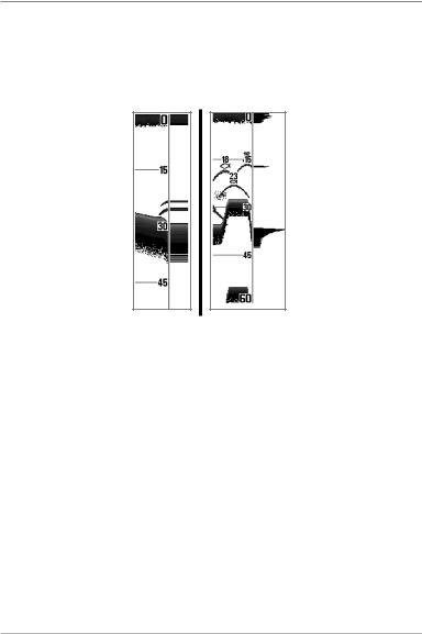
Bottom Presentation
As the boat moves, the unit charts the changes in depth on the display to create a profile of the Bottom Contour. The type of bo ttom can be determined from the return charted on the display. A Hard Bottom such as compacted sediment or flat rock appears as a thinner line across the display. A Soft Bottom such as mud or sand appears as a thicker line across the display. Rocky Bottoms have a broken, random appearance.
Bottom Contour Profile with RTS Window™
Rocky Bottom
Soft Bottom
Hard Bottom
The sonar returns from the bott om, structure, and fish can be represented as either WhiteLine™ or Structure ID®. See Sonar Menu Tab: Bottom View for details on how to set the bottom view.
11 |
What’s On the Sonar Display |
Structure ID® represents weak returns in blue and strong returns in red.
WhiteLine™ highlights the s trongest sonar r eturns in white, res ulting in a distinctive outline.This hasthe benefit of clearly defining the bottom on the display.
What’s On the Sonar Display |
12 |

Views
The sonar and navigation information from your Fishfinder is displayed on your screen in a variety of easy-to-read views. There are many views available on your Fishfinder. When you press the VIEW key, the display cycles through the available views on your screen. When you press the EXIT key, the display cycles through the available views in reverse order.
When you first power up the control head, Sonar View will be the default view.
You can display and hide any view to suit your fishing preferences.
Cha trnoS/ |
ra |
iVCombo |
we |
Cha tr iVwe
riB d’s eyE iVwe
GPS
aiD gnost ci iVwe
Sona r
View
Sonar Zoom
View
giB iD ig st iVwe
Sel f eT st iVwe
Ac se sor y eT ts View
NOTE: When you change any menu settings that affect the sonar,the view will update immediately. Youdon't have to exit the menu to apply the change to the screen.
13 |
Views |

To customize your views rotation:
You can choose which views are hidden or visible in your view rotation.
1.Press the M ENU key t wice t o acc ess th e tab bed Main Menu, then press the RIGHT Cursor key until the Views tab is selected.
2.Press the UP or DOWN Cursor keys to select a View.
3.Press the LEFT or RIGHT Cursor keys to change the status of the view from Hidden to Visible or vice versa.
To change the Digital Readouts:
Each view displays digital readout information (such as sp eed or time), which varies with the view selected, the accessory attached, and whether or not you are navigating. The digital readouts on the Sonar View can be customized. See
Setup Menu Tab: Select Readouts for more information.
1.Press the M ENU key t wice t o acc ess th e tab bed Main Menu, then press the RIGHT Cursor key until the Setup tab is selected.
2.Press the DOWN key to highlight Select Readouts, and press the RIGHT Cursor key to access the Select Readouts submenu.
NOTE: If the Select Readouts option does not appear under theSetup tab, change the User Mode to Advanced.
3.Press the UP or DOWN Cursor keys to select a Readout position, then press the RIGHT or LEFT Cursor keys to choose what will be displayed in that position. To hide the data window, select Off. (Course, Navigation, Off, Position, Speed, Temperature, Time+Date, Triplog, Voltage)
Views |
14 |

The available views are shown here and described on the following pages.
Sonar views: |
Navigation views: |
Sonar View |
Bird’s Eye View |
Sonar Zoom View |
Chart View |
Big Digits View |
Chart/Sonar Combo View |
Self Test View |
|
(see Start-Up Options Menu) |
|
Accessory Test View |
|
(see Start-Up Options Menu) |
|
GPS Diagnostic View |
|
(see Start-Up Options Menu) |
|
15 |
Views |
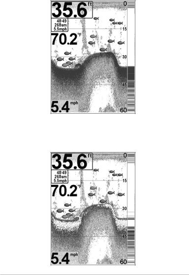
Sonar View
Sonar View presents a historical log of sonar ret urns. The most recent sonar returns ar e char ted on the right side of the wi ndow. As new information i s received, the historical information scrolls left across the display.
•Upper and Lower Depth Range numbers indicate the distance from the surface of the water to a depth range sufficient to show the bottom.
•Depth is automatically selected to keep the bottom visible on the display, although you can adjust it manually as well(see Sonar X-Press™ Menu).
•Digital Readouts shown on the display will change based on the Select Readouts settings or t he optional-purchase accessories attached (see
Setup Menu Tab: Select Readouts).
•Freeze Frame - Use the 4-WAY Cursor Control key to freeze the display and move the cursor over a sonar return. The depth of the sonar return will be displayed at the bottom of thescreen in the cursor information box.
Sonar View
Depth |
|
Upper Depth |
|
Range |
|
|
|
Temperature 
Cursor
Triplog
Speed
 RTS Window™
Sonar History
Window
Cursor |
|
Lower Depth |
|
||
Dialog Box |
|
Range |
NOTE: If the Depth number is flashing, it means that theunit is havingtroublelocating the bottom. This usually happens if the water is too deep, the transduceris out of the water, the boat is moving too fast, or for any other reasonthat the unitcan’t accurately receive continuous data.
Views |
16 |
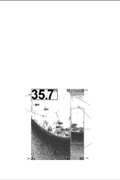
Sonar Zoom View
Sonar Zoom View provides a magnified view of the bottom and structure. The Sonar Zoom View makes it easier to see sep arate so nar return s that would usually be displayed close together, such as t hose caused by fish su spended close to the bottom or within structure.
•The Zoom Level, or magnification, is displayed in the lower left corner of the d isplay. Press the + o r - Z OOM keys to increase or d ecrease the zoom level.
•The Z oomed View is dis played on the le ft sid e o f th e screen. As the depth changes, the zoomed view updates automatically.
•The Full Range View is displayed on the right side of the screen. The Full Range View includes the Zo om Preview Box, which sho ws where the zoomed view is in relation to the full range view.
•The Upper and Lower Depth Range numbers indicate the high and low range of the water which is being viewed.
|
|
|
Sonar Zoom View |
||||
|
|
|
|
|
|
|
|
|
|
|
|
|
|
|
Upper Depth Range, |
|
|
|
|
|
|
||
Depth |
|
|
|
|
|
|
Full Range View |
|
|
|
|
|
|
|
|
|
|
|
|
|
|
|
Upper Depth Range, |
Zoomed View |
|
|
|
|
|
|
Zoom View |
|
|
|
|
|
|
|
Full Range View |
|
|
|
|
|
|
|
Zoom Preview Box |
|
|
|
|
|
|
|
Lower Depth Range, |
|
|
|
|
|
|
|
Zoom View |
|
|
|
|
|
|
|
Lower Depth Range, |
Zoom Level |
|
|
|
|
|
|
Full Range View |
|
|
|
|
|
|||
|
|
Digital depth is displayed in the upper left hand corner. |
|
||||
|
|
|
|||||
|
|
The digital readouts in the Sonar Zoom View cannot |
|||||
|
|
be customized; therefore, information such as water |
|||||
|
|
temperature and voltage are unavailable in the Sonar |
|||||
|
|
Zoom View. |
|||||
17 |
Views |
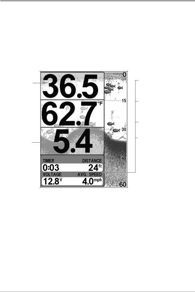
Big Digits View
Big Digits V iew provides digital dat a in a large, easy-to-see format. Depth is always displayed. Readouts for temperature, speed, and Triplog information are displayed automatically if t he appropriat e a ccessory is connected to the system. The Triplog shows distance traveled, average speed, and time elapsed since the Tr iplog w as last reset. The digital reado uts in t he Big Digits View cannot be customized.
Big Digits View
Depth
Temperature 
Speed
Timer shows the
time elapsed since Triplog was last reset
Distance is the distance traveled since the Triplog was last reset
Voltage displays the battery voltage
Average Speed shows the speed since the Triplog was last reset
Views |
18 |
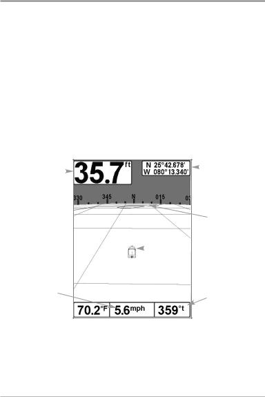
Bird’s Eye View
Bird's Eye View shows a 3D perspective view of the track and the chart’s land contour from a point above andbehind theboat (the eye point). As the boat turns, the eye pointmoves to follow the boat.
When you press the 4-WAY Cursor ontrolC key in theBird’s Eye View, the position of the eye point will shift. This allows youto move and turn the eye point so that you can look off to thesides, or even behind the boat. Pressing the RIGHT or LEFT arrow keys on the 4-WAY Cursor Control key turns the eye point right or left, while pressing the UP arrow key moves the eye point forward, and pressing the DOWN arrow key moves the eye point backward.
Pressing the EXIT key moves the eye point back to its original position behind and above the boat.
Bird’s Eye View
Depth |
|
|
|
|
Latitude and |
|
|
|
|
||
|
|
|
|
Longitude |
|
|
|
|
|
|
|
|
|
|
|
|
Position |
|
|
|
|
|
of Boat |
|
|
|
|
|
Land Contours |
|
|
|
|
|
Boat Icon |
|
|
|
|
|
Speed of Boat |
Bearing of Boat |
|
|
|
with Respect to |
|
True North |
19 |
Views |
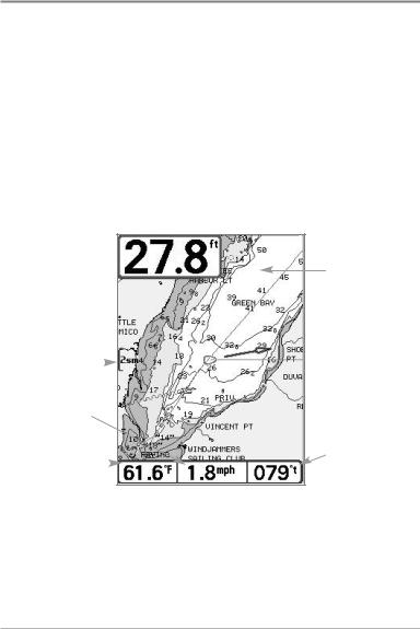
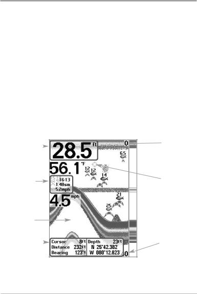
Chart View
Chart View shows cartography fr om t he bu ilt-in U niMap™ or an optional MMC/SD map for the area surrounding your current position. The current track (also known as t he position hist ory or b readcrumb trail) sh owing w here the boat has been, along with saved tracks, waypoints, and the current route (when navigating), are overlaid on the chart.
•Use the 4-WAY Cursor Controlkey to shift/pan the chart to another area.
•Press the ZOOM (+/-) keys to zoom in and out.
•Press the INFO key to get information on the chart objects near the cursor.
Chart View without Active Cursor, shown with
Optional-Purchase Navionics® Cartography
Depth 
Cartography
Map Scale |
|
|
|
|
|
|
|
Speed of Boat |
|
|
|
Water Surface |
|
|
Bearing of Boat |
|
|
with Respect |
|
Temperature |
|
|
to True North |
Views |
20 |
Loading...