


INSTALLATION PREPARATION
PARTS SUPPLIED
PARTS SUPPLIED
Before installing your new Humminbird fishfinder, please ensure the following parts are included in the box:
∙Fishfinder
∙Transducer with 20’ (6m) of cable and mounting hardware kit
∙Mounting system and mounting hardware kit
∙6’ (2m) power cable
∙Publications kit
It any of these items is missing, call our Customer Support Hotline.
ACCESSORIES
Humminbird offers a wide assortment of accessories that complement and expand the capability of your new fishfinder. These accessories are designed with the same high standards and are backed by the same one-year warranty. The Humminbird Accessory catalog included with your unit contains descriptions of the many accessories available and ordering information. All Humminbird accessories are available through your full-service Humminbird dealer or factory direct through our number listed in the Customer Support section.
INSTALLATION OVERVIEW
Your Humminbird fishfinder consists of two primary components to install: the control head and the transducer.
The control head contains the sonar transmit and receive circuitry, as well as the user controls and display. It should be installed in a location that provides access to the controls and visibility while in use. The control head mounts on a quick disconnect mounting system that swivels and tilts providing flexibility for viewing from almost anywhere on the boat.
The transducer converts electrical energy from the transmitter into mechanical pulses or sound waves. The transducer also receives the reflected sound waves and converts them back into electrical signals for display on the control head. It should be installed in contact with the surface of the water in an area that has smooth waterflowusually on the transom of the boat. There are several mounting options for the transducer. Review the following section to determine the method that works for you and your boat.
INSTALLATION PREPARATION
INSTALLATION OVERVIEW
Determining How to Mount the Transducer
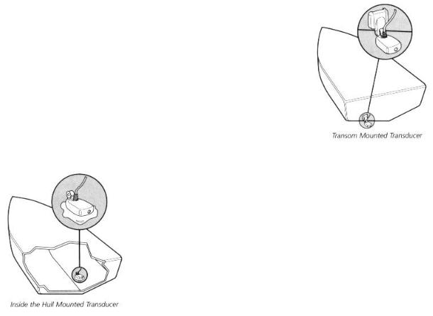
Your Humminbird fishfinder includes a standard transducer. This transducer can be mounted on the transom of the boat or bonded to the inside of a fiberglass hull boat.
The transom installation, which is the most widely used, places the transducer on the outside of the boat hull. This technique produces the least signal loss, and provides a way to adjust the transducer after installation. The mounting hardware included is designed to protect both the boat and the transducer should the boat strike debris in the water or when trailering.
As an alternative to transom mounting, it is possible on many fiberglass-hulled boats to glue the transducer on the inside of the boat hull. Since fiberglass has similar sonar characteristics as water, the sonar signal can pass through the boat hull with minimal loss. The hull of the boat must be single layer construction (not double-hulled) Also, any air trapped in the lamination of the fiberglass would prevent the sonar signal from passing through.
Inside the hull installations require no holes be drilled into the boat and through experimentation, high-speed
operation comparable to transom mounting can be achieved. Two-part slow cure epoxy (not included) is required to glue the transducer in place.
INSTALLATION PREPARATION
ALTERNATE MOUNTING METHODS
ALTERNATE TRANSDUCERS AND MOUNTING METHODS
Your Humminbird fishfinder comes with everything necessary for installation and operation on most boats. However, there are several situations which may require a different type of transducer. Inboard boats, wood or metal hulls, and sail boats create unique transducer mounting needs Alternate transducers and mounting methods are detailed below.
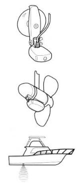
Portable Mounting
The standard transducer can be adapted for portable installations with a portable mounting kit available from Humminbird. This accessory adapts your transducer to a suction cup mount for temporary installation on the boat hull or other surface.
Trolling Motor Mounting
The standard transducer can also be adapted to mount on most trolling motors using a different accessory kit. This accessory includes a bracket and hose clamp that allows mounting the transducer to the body of most trolling motors.
Thru-Hull Mounting
Thru-hull transducers install through a hole drilled in the hull
of the boat. Larger boats or boats with inboard motors create turbulence that make transom mounting ineffective. Also, hulls that are very thick or are double layered, or made from materials such as wood or metal, (which do not conduct sonar signals) make inside the hull mounting inadvisable.
Thru-hull mounting may require the use of a fairing block to level the transducer with the waterline. Also, since special tools and knowledge may be required to perform this type of installation, it is best to refer to a qualified marine technician.
INSTALLATION PREPARATION
TRANSDUCER EXCHANGE
TRANSDUCER EXCHANGE
Other transducers are available as replacements for the standard transducer. You may exchange your new and unassembled transducer for another type by returning it to the address listed in Customer Support. Some transducers may have additional cost. Refer to the Accessory catalog or call Customer Support for information.
BEGINNING INSTALLATION
Now that you have determined the transducer mounting method you can begin installation of your new Humminbird fishfinder. The installation guide included on the next few pages provides detailed step by step instructions for installation of the control head and transducer. For transom mount transducer installations you will need the mounting template included with your manual.
In addition to the parts included you need the following for installation and operation:
∙A powered hand drill and various drill bits
∙Philips and flat-head screwdrivers
∙A ruler or measuring tape
∙Pen or pencil
∙12 volt power source (your boat’s battery)
∙A 1-amp fuse
∙A fuse holder (if you are wiring directly to the boat’s battery)
∙Silicone sealant (for sealing drilled holes)
∙2-part, slow-cure epoxy (for inside the hull transducer installations)

INSTALLATION
TRANSOM INSTALLATION
Do not begin this transducer installation until you read the Installation Preparation in the Operation Guide. This chapter contains information critical to the correct installation of your transducer.
Due to the wide variety of boat hulls, only general instructions are presented in the installation guide. Each boat hull represents a unique set of requirements that should be evaluated prior to installation.
TRANSOM INSTALLATION
Step One - Determine Where to Mount the Transducer
Begin the transducer installation by determining where on the transom to install the transducer. Consider the following to find the best location:
∙It is very important to locate the transducer in an area which is relatively free of turbulent water, As a boat moves through the water, turbulence is generated by the weight of the boat, and the thrust of the propeller(s). This turbulent water is normally confined to areas immediately aft of ribs, strakes or rows of rivets on the bottom of the boat, and in the immediate area of the propeller(s) (Figure 1). On outboard or inboard/outboard boats it is best to stay at least 15” (40cm) to the side of the propeller(s).
∙If possible, viewing the transom of the boat while the boat is moving will provide the best means of locating turbulence free water. If maximum high-speed operation is a high priority, this is the recommended method. If this is not possible, select a location on the transom where the hull forward of this location is smooth, flat, and free of protrusions or ribs.
∙The transducer when mounted should point straight down. The design of the transducer will accommodate a wide range of deadrises and remain ported straight down (Figure 2).
∙On boats with stepped hulls, it may be possible to mount the transducer on the step. Never mount the transducer on the transom behind a step, as this area of the transom will not be in contact with the water at high speed (Figure 3).
INSTALLATION
TRANSOM INSTALLATION
∙If the propeller(s) is (are) forward of the transom, it may be impossible to find an area clear from turbulence, and a different mounting technique or transducer type should be considered.
Step Two - Drill the Mounting Holes
1.Remove the mounting template from the front of the Operations Manual.
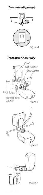
2.Hold the template on the transom of the boat in the location where the transducer will be installed (Figure 4). Align the template vertically, ensuring the lower edge of the transom meets with the bottom corner
of the template.
3.Using a pencil or punch, mark the two mounting holes shown on the template onto the transom. Do not mark or drill any other holes at this time.
4.Using a 5/32” (4mm) bit drill the two holes to a depth of approximately 1" (3cm). On fiberglass hulls, it is best to start with a smaller bit and use progressively larger drill bits to reduce the chance of chipping or flaking the outer coating.
Step Three - Assemble the Transducer
1.Attach the Pivot to the transducer body as shown in Figure 5, using the #8 – 3/8” (9mm) long allen headed pivot screw, the headed pin, the two flat washers, and the two toothed lock washers.
Note: The toothed lock washers must be positioned between the transducer and the pivot ears. The flat washers must be positioned to the outside at the pivot ears.
2.Using the AIlen wrenches provided, loosely tighten the pivot screw (Figure 6). Do not completely tighten the assembly at this time, so the pivot angle can be adjusted later.
3.Insert the pivot/transducer assembly into the mounting bracket as shown in Figure 7. Do not snap the assembly closed.
INSTALLATION
TRANSOM INSTALLATION
Step Four - Mount the Transducer to the Transom
1.Apply silicone sealant to the mounting holes drilled into the transom.
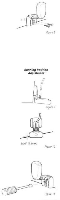
2.Align the transducer assembly with the drilled holes in the transom (Figure 8).
3.Use either a flat head screwdriver, a 5/16" (8mm) hex driver, or a 5/16" (8mm) socket to mount the assembly. Using the two #10 – 1”
(25mm) long slotted hex head screws, mount the transducer assembly to the transom as shown. Do not fully tighten the mounting screws in order to vertically adjust the transducer. Snap the pivot down into place.
Step Five - Adjust the Running Position of the Transducer
The bracket allows height and tilt adjustment, the pivot screws allow angular adjustment. Initially, adjust the transducer as described in the following paragraphs. Further adjustment may be necessary to refine the instillation after high speed testing.
1.First adjust the pivot angle of the transducer body so its length is parallel with the length of hull of the boat. Then pivot the transducer down so the rear is about 1/4 inch (6mm) lower than the front (Figure 9).
2.Fully tighten the two pivot screws using the Allen wrenches. It may be necessary to retighten the pivot screws after the initial use as the plastics may still be seating to the lock washers.
3.Adjust the height of the assembly so the face of the transducer is 3/16" (4.5mm) beneath the lower edge of the transom (Figure 10). Mark the position of the mounting bracket on the transom with a pencil.
4.Force the pivot to the up position to gain access to the mounting screws. Assure the transducer location has not changed, then fully tighten the two mounting screws (Figure 11). Snap the pivot back down.
Confirm the pivot angle has not changed.
Note: A third screw location is provided for the
 Loading...