


 Loading...
AC Controls
Manual Starters and Switches
General
Type F02
Class SMF
Class SMF fractional horsepower starters provide overload protection as well as manual ON / OFF control for small motors in a variety of industrial and commercial installations.
Available in one or two pole versions, these devices are suitable for use with AC single phase motors to 1 HP. Two pole starters can also be used with DC motors to 3⁄4 HP. Typical applications include fans, conveyors, pumps, and small machine tools. The continuous current rating is 16 amperes.
Overload trip assembly motor protection is provided by a Type SMFH thermal heater element which must be installed before the starter will operate.
Two-Speed Class SMF manual starters are designed for control of small single phase AC motors having separate windings for high and low speed operation.
Two toggle operated starters are used, with overload protection included for each motor winding. Surface mounting devices, and those with a gray flush plate, utilize a mechanical interlock which allows direct control of the motor by means of the toggle operators.
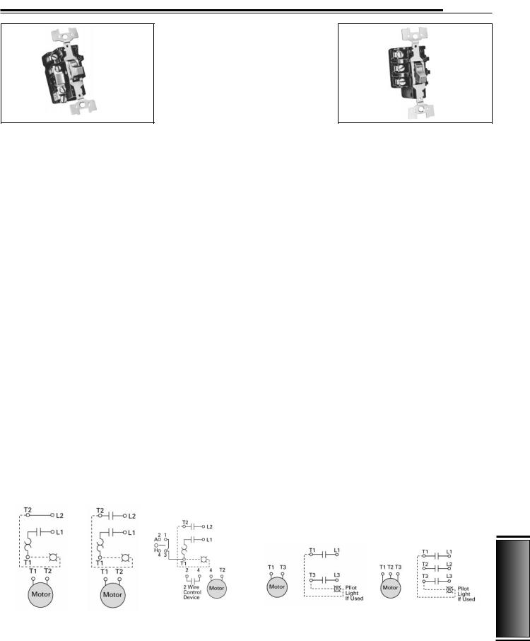
Typical Wiring Diagrams
Class MMS and MRS
These motor starting switches provide manual ON / OFF control of single or three-phase AC motors, where overload protection is not required, or is provided separately.
These devices are suitable for use with AC three-phase motors up to 10 HP. Compact construction and a 600 volt rating make these switches suitable for a wide range of industrial and commercial uses. Typical applications include small machine tools, pumps, fans, conveyors, and many other types of electrical machinery. They can also be used on non-motor loads such as resistance heaters.
The continuous current rating is 30 amperes at 250 volts max., 26.4 amperes at 277 volts max., 20 amperes at 600 volts max, 30 ampere resistive at 600 volts max.
Class MMS, two-speed manual switches may be used with separate winding, three-phase or single-phase AC motors where overload protection is not required, or is provided separately. Two switches are employed to give ON / OFF control in each speed.
Class MRS, reversing manual switches provide a compact means of starting, stopping and reversing AC motors where overload protection is not required, or is provided separately. They are suitable for use with three-phase squirrel cage motors, and for single-phase motors which can be reversed by reconnecting motor leads. Two switches are used, one to connect the motor for forward rotation, and one for reverse.
Class SMF, MMS and MRS
NEMA Type 1 surface mounting enclosures are sheet steel with a thermoplastic wrap-around cover for convenience in wiring. The NEMA Type 1 enclosure is also available in oversized and jumbo
Type K02
versions allowing more wiring space. A zinc alloy die casting or non-metallic enclosure is used for NEMA Type 4 enclosures. NEMA 7 & 9 enclosures are supplied as standard with provisions for locking in the ON or OFF position.
Standard red or non-standard green neon pilot light units are available factory installed in NEMA Type 1 surface and flush mounting, and NEMA Type 4 enclosures, or as a field modification kit for NEMA Type 1 enclosures and gray flush plates.
An “Emergency-OFF” toggle operator extender is available for NEMA Type 1 surface mounted units. The extender has a red vinyl button that provides a fast and easy method for locating and switching the device’s toggle operator into the OFF position. The Emergency OFF Actuator is available in kit form only for field installation.
An optional Handle Guard / Lock-OFF on NEMA Type 1 enclosed starters prevents accidental operation of the toggle and also allows the toggle operator to be padlocked in either the ON or the OFF position. This handle guard can be factory installed on NEMA Type 1 enclosed starters and is also available in kit form for field installation on NEMA Type 1 surface and flush mounting enclosures. Standard NEMA Type 4 metallic enclosures include provision for padlocking in the OFF position.
Class SMF |
|
|
|
|
|
Class MMS |
|
|
|
||
|
|
|
|
|
|
|
|
|
|
|
|
|
|
|
|
|
|
|
|
|
|
|
|
|
|
|
|
|
|
|
|
|
|
|
|
|
|
|
|
|
2 Pole with |
|
|
|
|
|
|
|
|
|
|
|
|
|
|
|
|
|
|
|
|
|
|
|
|
|
|
|
|
|
|
|
|
|
|
|
|
|
|
|
|||
|
1 Pole |
|
2 Pole |
|
Selection Switch |
|
|
2 Pole –– 1 Phase |
|
3 Pole –– 3 Phase |
|
|
|
|
|
|
|
|
|
|
|
|
|
|
|
|
|
|
|
|
|
|
|
|
|
15
Controls AC
CSI Section 16160 |
Siemens Electrical Products and Systems |
285 |
|
Specification Guide |
|
AC Controls
Manual Starters and Switches
General
Type F02
Class SMF
Class SMF fractional horsepower starters provide overload protection as well as manual ON / OFF control for small motors in a variety of industrial and commercial installations.
Available in one or two pole versions, these devices are suitable for use with AC single phase motors to 1 HP. Two pole starters can also be used with DC motors to 3⁄4 HP. Typical applications include fans, conveyors, pumps, and small machine tools. The continuous current rating is 16 amperes.
Overload trip assembly motor protection is provided by a Type SMFH thermal heater element which must be installed before the starter will operate.
Two-Speed Class SMF manual starters are designed for control of small single phase AC motors having separate windings for high and low speed operation.
Two toggle operated starters are used, with overload protection included for each motor winding. Surface mounting devices, and those with a gray flush plate, utilize a mechanical interlock which allows direct control of the motor by means of the toggle operators.
Typical Wiring Diagrams
Class MMS and MRS
These motor starting switches provide manual ON / OFF control of single or three-phase AC motors, where overload protection is not required, or is provided separately.
These devices are suitable for use with AC three-phase motors up to 10 HP. Compact construction and a 600 volt rating make these switches suitable for a wide range of industrial and commercial uses. Typical applications include small machine tools, pumps, fans, conveyors, and many other types of electrical machinery. They can also be used on non-motor loads such as resistance heaters.
The continuous current rating is 30 amperes at 250 volts max., 26.4 amperes at 277 volts max., 20 amperes at 600 volts max, 30 ampere resistive at 600 volts max.
Class MMS, two-speed manual switches may be used with separate winding, three-phase or single-phase AC motors where overload protection is not required, or is provided separately. Two switches are employed to give ON / OFF control in each speed.
Class MRS, reversing manual switches provide a compact means of starting, stopping and reversing AC motors where overload protection is not required, or is provided separately. They are suitable for use with three-phase squirrel cage motors, and for single-phase motors which can be reversed by reconnecting motor leads. Two switches are used, one to connect the motor for forward rotation, and one for reverse.
Class SMF, MMS and MRS
NEMA Type 1 surface mounting enclosures are sheet steel with a thermoplastic wrap-around cover for convenience in wiring. The NEMA Type 1 enclosure is also available in oversized and jumbo
Type K02
versions allowing more wiring space. A zinc alloy die casting or non-metallic enclosure is used for NEMA Type 4 enclosures. NEMA 7 & 9 enclosures are supplied as standard with provisions for locking in the ON or OFF position.
Standard red or non-standard green neon pilot light units are available factory installed in NEMA Type 1 surface and flush mounting, and NEMA Type 4 enclosures, or as a field modification kit for NEMA Type 1 enclosures and gray flush plates.
An “Emergency-OFF” toggle operator extender is available for NEMA Type 1 surface mounted units. The extender has a red vinyl button that provides a fast and easy method for locating and switching the device’s toggle operator into the OFF position. The Emergency OFF Actuator is available in kit form only for field installation.
An optional Handle Guard / Lock-OFF on NEMA Type 1 enclosed starters prevents accidental operation of the toggle and also allows the toggle operator to be padlocked in either the ON or the OFF position. This handle guard can be factory installed on NEMA Type 1 enclosed starters and is also available in kit form for field installation on NEMA Type 1 surface and flush mounting enclosures. Standard NEMA Type 4 metallic enclosures include provision for padlocking in the OFF position.
Class SMF |
|
|
|
|
|
Class MMS |
|
|
|
||
|
|
|
|
|
|
|
|
|
|
|
|
|
|
|
|
|
|
|
|
|
|
|
|
|
|
|
|
|
|
|
|
|
|
|
|
|
|
|
|
|
2 Pole with |
|
|
|
|
|
|
|
|
|
|
|
|
|
|
|
|
|
|
|
|
|
|
|
|
|
|
|
|
|
|
|
|
|
|
|
|
|
|
|
|||
|
1 Pole |
|
2 Pole |
|
Selection Switch |
|
|
2 Pole –– 1 Phase |
|
3 Pole –– 3 Phase |
|
|
|
|
|
|
|
|
|
|
|
|
|
|
|
|
|
|
|
|
|
|
|
|
|
15
Controls AC
CSI Section 16160 |
Siemens Electrical Products and Systems |
285 |
|
Specification Guide |
|

AC Controls
Manual Starters and Switches
General
Table 15.1 Horsepower Ratings
|
Maximum Horsepower |
||
|
AC Single Phase |
DC 2-Pole Only |
|
Voltage |
1-Pole |
2-Pole |
|
115–230 |
1 |
1 |
3⁄4 |
277 |
1 |
1 |
— |
Table 15.2 |
Horsepower Ratings |
|
|
|
|
|
|
||
|
Number |
|
AC Ratings |
|
DC Ratings |
|
|||
|
of |
Motor Type |
115 |
230 |
460–575 |
90 |
115 |
230 |
|
Device |
Poles |
AC |
Volts |
Volts |
Volts |
Volts |
Volts |
Volts |
|
Class |
2 |
Single Phase |
2 |
2 |
3 |
1 |
2 |
11⁄2 |
|
MMS |
3 |
Three Phase |
2 |
71⁄2 |
10 |
1 |
2 |
11⁄2 |
|
Class |
2 |
Single Phase |
2 |
2 |
3 |
1 |
2 |
11⁄2 |
|
MRS |
3 |
Three Phase |
2 |
71⁄2 |
10 |
1 |
2 |
11⁄2 |
|
Class |
2 |
Single Phase |
2 |
2 |
3 |
1 |
2 |
11⁄2 |
|
|
3 Phase, Constant |
|
71⁄2 |
|
|
|
11⁄2 |
||
MMS |
3 |
2 |
10 |
1 |
2 |
||||
or Var. Torque |
|||||||||
Two |
|
|
|
|
|
|
|
||
Speed |
3 |
3 Phase, |
2 |
71⁄2 |
10 |
1 |
2 |
1 |
|
|
|
Constant HP |
|
|
|
|
|
|
|
15
AC Controls
Table 15.3 |
Manual Starters and Switches Features |
|
|
|
|
|
|
Class SMF Fractional Horsepower |
Class MRS and MMS Manual |
|
|||||
Manual Starters with Melting |
Switches |
|
|
|
|
||
Alloy Type Thermal Overload Relay, |
|
|
|
|
|
||
Single Unit Types |
|
|
|
|
|
|
|
Type of |
No. of |
|
Type of |
No. of |
|
|
|
Operator |
Poles |
Features |
Operator |
Poles |
|
Features |
|
Basic Starter |
|
|
Class MMS — Non-Reversing |
|
|||
Toggle |
1 |
|
Toggle |
1 |
|
Standard With Pilot Light (115 and 230 VAC) |
|
|
2 |
Standard With Red Pilot Light |
|
2 |
|
Standard With Pilot Light (205–240 and 440–600 VAC) |
|
Key |
1 |
Key |
1 |
|
Standard With Pilot Light (115 and 230 VAC) |
||
|
|
||||||
|
2 |
|
|
2 |
|
Standard With Pilot Light (208–240 and 440–600 VAC) |
|
Starter With Handle Guard / Lock-Off |
|
|
|
|
Features |
||
Toggle |
1 |
|
Type of |
No. of |
|
Suitable for |
(Incl. Mechanical |
|
Operator |
Poles |
|
Motor Types |
Interlock) |
||
|
2 |
Standard With Red Pilot Light |
Class MMS — Reversing |
|
|
||
|
1 |
|
|
||||
|
|
Toggle |
2 |
|
Single-Phase Two- |
Std. With Pilot Light |
|
|
2 |
|
|
Winding (3-Lead) |
(115 and 230 VAC) |
||
|
|
|
|
|
|||
One Starter In Duplex Enclosure |
|
|
|
3-Phase and 1-Phase |
Std. With Pilot Light |
||
Toggle |
2 |
|
|
3 |
|
Capacitor, Split-Phase |
(110–120, 208-220, |
|
|
Standard With Red Pilot Light |
|
|
|
4-Lead Repul.-Induct. |
440–600 VAC) |
Key |
2 |
|
|
|
|||
|
|
|
Class MMS — Two-Speed |
|
|||
Two Starters In One Enclosure |
|
||||||
Toggle |
2 Each |
|
Toggle |
2 |
|
Single-Phase Two- |
Std. With 2 Pilot Lights |
|
Standard With Red Pilot Light On Each |
|
|
|
Winding (3-Lead) |
(115 and 230 VAC) |
|
|
|
|
|
||||
Key |
Str. |
|
|
|
|
Three-Phase |
Std. With 2 Pilot Lights |
Starter and “Auto-Off-Hand” SPDT Selector Switch (AC Only) |
|
3 |
|
Separate Winding |
(208-220, and |
||
Toggle |
1 |
Standard With Red Pilot Light |
|
|
|
(Wye-Connected) |
440–600 VAC) |
|
|
|
|
|
|||
|
2 |
|
|
|
|
|
|
|
|
|
|
|
|
|
|
Key |
2 |
With Red Pilot Light |
|
|
|
|
|
Two-Speed Starters (AC Only) |
|
|
|
|
|
||
Toggle |
1 |
With Mechanical Interlock (Standard With 2 Red Pilot Lights) |
|
|
|
|
|
|
2 |
With High-Off-Low Selector Switch (With 2 Red Pilot Lights) |
|
|
|
|
|
Table 15.4 Class SMF Heater Elements
Motor Full-Load |
Heater |
Motor Full-Load |
Heater |
Motor Full-Load |
Heater |
Motor Full-Load |
Heater |
||
Current (Amperes) |
Cat. No. |
Current (Amperes) |
Cat. No. |
Current (Amperes) |
Cat. No. |
Current (Amperes) |
Cat. No. |
||
0.157–0.173 |
SMF H01 |
0.59–0.65 |
SMF H014 |
1.80 |
–1.99 |
SMF H027 |
5.86 |
–6.41 |
SMF H40 |
0.174–0.192 |
SMF H02 |
0.66–0.71 |
SMF H015 |
1.96–2.15 |
SMF H028 |
6.42–6.79 |
SMF H41 |
||
0.193–0.212 |
SMF H03 |
0.72–0.78 |
SMF H016 |
2.16–2.38 |
SMF H029 |
6.80–7.57 |
SMF H42 |
||
0.213–0.235 |
SMF H04 |
0.79–0.85 |
SMF H017 |
2.39–2.75 |
SMF H030 |
7.58 |
–8.15 |
SMF H43 |
|
0.236–0.261 |
SMF H05 |
0.86–0.96 |
SMF H018 |
2.76–2.84 |
SMF H031 |
8.16 |
–8.98 |
SMF H44 |
|
0.262–0.289 |
SMF H06 |
0.97–1.04 |
SMF H019 |
2.85–3.06 |
SMF H032 |
8.99 |
–9.67 |
SMF H45 |
|
0.290–0.321 |
SMF H07 |
1.05–1.16 |
SMF H020 |
3.07–3.45 |
SMF H033 |
9.68 |
–9.95 |
SMF H46 |
|
0.322–0.355 |
SMF H08 |
1.17–1.25 |
SMF H021 |
3.46–3.70 |
SMF H034 |
9.96 |
–10.8 |
SMF H47 |
|
0.356–0.399 |
SMF H09 |
1.30–1.39 |
SMF H022 |
3.71–4.07 |
SMF H035 |
10.9 |
–12.1 |
SMF H48 |
|
0.40–0.44 |
SMF H010 |
1.38–1.54 |
SMF H023 |
4.08–4.32 |
SMF H036 |
12.2–13.1 |
SMF H49 |
||
0.45–0.49 |
SMF H011 |
1.48–1.63 |
SMF H024 |
4.33–4.90 |
SMF H037 |
13.2–13.9 |
SMF H50 |
||
0.50–0.53 |
SMF H012 |
1.57–1.75 |
SMF H025 |
4.91–5.35 |
SMF H038 |
14.0 |
–15.0 |
SMF H51 |
|
0.54–0.58 |
SMF H013 |
1.66–1.86 |
SMF H026 |
5.36–5.85 |
SMF H039 |
15.1–16.0 |
SMF H52 |
||
286 |
Siemens Electrical Products and Systems |
CSI Section 16160 |
|
Specification Guide |
|||
|
|

AC Controls
Manual Starters and Switches
Table 15.5 General Purpose Flush Mounting
|
|
|
Dimensions |
|
|
|
Type of |
|
in Inches (mm) |
|
|
Device |
Operator |
Type |
A |
B |
C |
Class |
|
FF1, 1P, 2, 2P |
1.44 |
2.75 |
4.50 |
SMF |
Toggle |
FS1, 1P, 2, 2P |
(37) |
(70) |
(114) |
Fractional |
|
|
|
|
|
|
1.44 |
3.50 |
5.25 |
||
HP Starter |
|
FSJ1P, 2P |
|||
|
(37) |
(89) |
(133) |
||
|
|
|
|||
|
|
FF3, 3P, 4, 4P |
1.44 |
2.75 |
4.50 |
|
Key |
FS3, 3P, 4, 4P |
(37) |
(70) |
(114) |
|
FSJ3P, 4P |
1.44 |
3.50 |
5.25 |
|
|
|
||||
|
|
(37) |
(89) |
(133) |
|
|
|
|
|||
Class |
|
KF1, 1A, 1B, 2, 2B, 2C |
1.75 |
2.75 |
4.50 |
MMS |
Toggle |
FS1, 1A, 1B, 2, 2B, 2C |
(44) |
(70) |
(114) |
Motor |
|
|
|
|
|
|
1.75 |
3.50 |
5.25 |
||
Starting |
|
KSJ1A, 1B, 2B, 2C |
|||
|
(44) |
(89) |
(133) |
||
Switch |
|
|
|||
|
|
KF3, 3A, 3B, 4, 4B, 4C |
1.75 |
2.75 |
4.50 |
|
Key |
FS3, 3A, 3B, 4, 4B, 4C |
(44) |
(70) |
(114) |
|
KSJ3A, 3B, 4C, 4C |
1.75 |
3.50 |
5.25 |
|
|
|
||||
|
|
(44) |
(89) |
(133) |
|
|
|
|
|||
Table 15.6 Two Unit Devices
NEMA Type 1 General Purpose Enclosure
|
Type of |
|
|
Device |
Operator |
Class |
Type |
One Starter |
Toggle |
SMF |
FG02, 02P |
|
Key |
SMF |
FG04P |
Two Starters |
Toggle |
SMF |
FG222, 222P |
|
Key |
SMF |
FG44P |
One Str. and |
Toggle |
SMF |
FG71, 71P, 72, 72P |
One Sel. Sw. a |
Key |
SMF |
FG74P |
Reversing Switch b |
Toggle |
MRS |
KG11, 11A, 11B, 22, 22A, 22B |
|
|
|
22C |
Two Speed Starter |
Toggle |
SMF |
FG11, 11P, 22, 22P |
Two Speed Switch |
Toggle |
MMS |
KG11, 11A, 11B, 22, 22B, 22C |
a Selector switch is on left, increases overall depth to 3.5 in. (89mm) b Only one pilot light (located on right) is used on MRS switches.
Table 15.7 General Purpose Flush Mounting for Two Unit Devices
|
|
|
|
Dimensions |
|
|
||
|
Type of |
|
|
in Inches (mm) |
|
|
||
Device |
Operator |
Class |
Type |
A |
B |
C |
D |
|
Two |
Toggle |
SMF |
FF22, 22P |
5.25 (133) |
3.75 (95) |
5.25 (133) |
1.44 (37) |
|
Starters |
|
|
|
|
|
|||
FS22P |
4.56 (116) |
3.50 (89) |
4.50 (114) |
1.44 (37) |
||||
|
|
|
||||||
|
Key |
SMF |
FF44P |
5.25 (133) |
3.75 (95) |
5.25 (133) |
1.44 (37) |
|
|
FS44P |
4.56 (116) |
3.50 (89) |
4.50 (114) |
1.44 (37) |
|||
|
|
|
||||||
One |
Toggle |
SMF |
FF71, 71P, 72, 72P |
5.25 (133) |
0.75 (19) |
5.25 (133) |
2.00 (51) |
|
Starter |
FS71P, 72P |
4.56 (116) |
3.50 (89) |
4.50 (114) |
2.00 (51) |
|||
and One |
|
|
||||||
|
|
FF74P |
5.25 (133) |
3.75 (95) |
5.25 (133) |
2.00 (51) |
||
Selector |
Key |
SMF |
||||||
Switch 3 |
FS74P |
4.56 (116) |
3.50 (89) |
4.50 (114) |
2.00 (51) |
|||
Reversing |
|
|
KF11, 11A, 11B |
|
|
|
|
|
Switch |
Toggle |
MRS |
KF 22, 22A |
5.25 (133) |
3.75 (95) |
5.25 (133) |
1.75 (44) |
|
|
|
|
22B, 22C |
|
|
|
|
|
Two |
Toggle |
SMF |
FF11, 11P, 22 |
5.25 (133) |
3.75 (95) |
5.25 (133) |
1.44 (37) |
|
Speed |
22P |
|||||||
Starter |
|
|
|
|
|
|
||
Two |
|
|
KF11, 11A, 11B |
5.25 (133) |
3.75 (95) |
5.25 (133) |
1.75 (44) |
|
Speed |
Toggle |
MMS |
||||||
22, 22B, 22C |
||||||||
Switch |
|
|
|
|
|
|
||
3 Selector switch is on left, extends 1.62 in (41 mm) from mounting surface.
CSI Section 16160 |
Siemens Electrical Products and Systems |
|
Specification Guide |
Dimensions
15
Controls AC
287
AC Controls
Manual Motor Starter Switches
Dimension / Wiring Diagrams
3.97 in.
(100.8 mm)
Table 15.8 Explosion Proof
NEMA 7 & 9 Enclosures
|
Type of |
|
|
Device |
Operator |
Type |
|
Class SMF |
Toggle |
FR2, FR2H |
|
Fractional |
FR1, FR1H |
||
HP Starter |
|
||
|
|
|
|
Class MMF |
|
KR2, KR2H |
|
Motor |
Toggle |
||
Starter |
KR2, KR1H |
||
|
|||
Switch |
|
|
1.38 in. |
|
|
|
|
(35.05 mm) |
|
|
|
|
|
|
|
4.38 in. |
|
|
|
|
(111.25 mm) |
|
|
|
6.38 in. |
|
|
|
|
(162 mm) |
|
|
|
|
5.75 in. |
|
|
|
|
(146 mm) |
|
|
|
|
|
9⁄32 |
|
|
|
|
Padlock |
|
Center Line |
|
|
Hole |
|
|
|
|
|
|
(Conduit) |
|
|
0.75 in. -14 |
|
0.31 in. |
1.38 in. |
0.72 in. |
(19.05 mm) |
1.19 in. |
(7.94 mm) |
Pipe Tap |
(30.23 mm) |
||
Mtg. Holes |
(34.93 mm) |
(18.29 mm) |
(Bottom Only) |
|
|
|
|
|
|
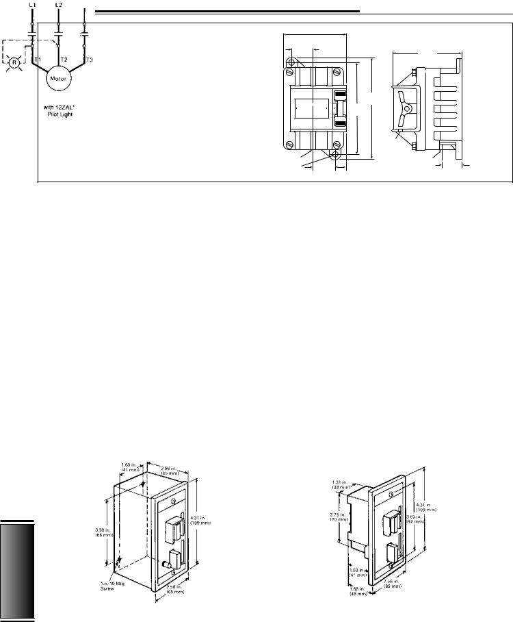
Application
Class 12 manual starting switches are designed to economically start and stop inherently protected single and polyphase motors as used in light machine tools, pumps, blowers, and vent-fans. They are also used as ON and OFF switches for resistive loads such as heating.
Wiring Diagrams
Features
This switch is compact, economical, and easily wired using pressure type screw connectors. A rugged over center toggle mechanism results in a long life with weld free operation. It is available for surface mounting in a NEMA 1 enclosure, for flush mounting on a standard depth switch box or in custom panels. A pilot light for 120, 208 / 240, or 480 volts may
be added at any time before or after installation.
Table 15.9
Class 12 Manual Starting Switches
|
Maximum Horsepower |
|
||
|
115 |
230– |
120V |
Continuous |
Type |
575 |
|||
Volts |
Volts |
DC |
Amp Rating |
|
1-Phase |
2 |
3 |
1 |
24 |
3-Phase |
— |
2 |
— |
15 |
1-Phase |
|
3-Phase |
|
|
|
|
|
||
|
|
|
|
|
|
|
|
|
|
Dimension Drawings
15
AC Controls
NEMA 1 |
Open with Flush Plate |
|
|
|
|
288 |
Siemens Electrical Products and Systems |
CSI Section 16160 |
|
Specification Guide |
|||
|
|
AC Controls
Manual Motor Starter Protector
General / Dimensions
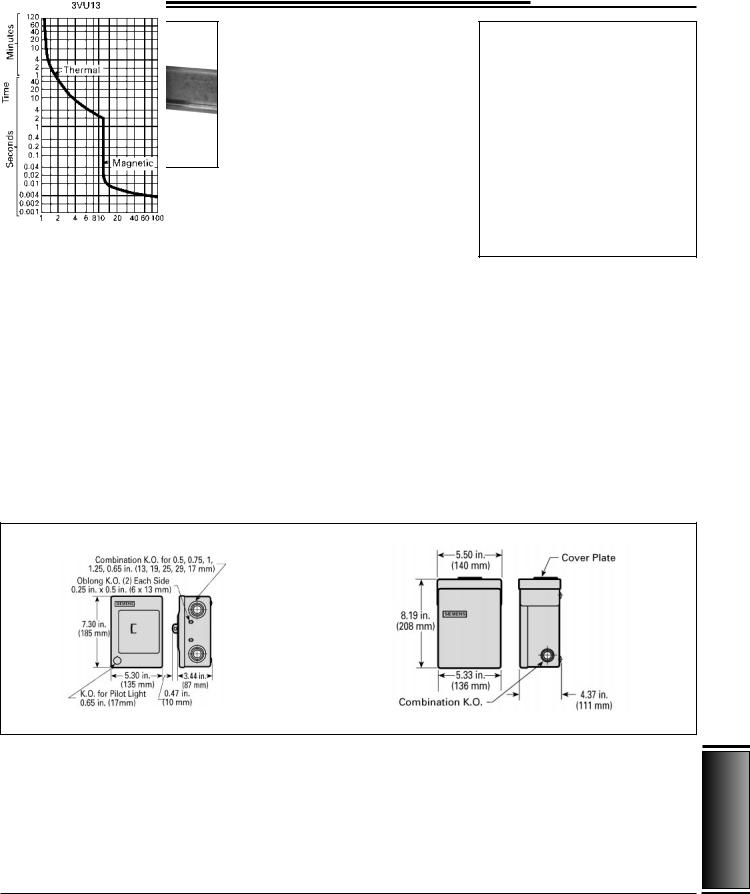
Type 3VU13 Manual Motor Starter
Protector
Siemens 3VU13 is a 3-phase manual starter providing adjustable overload protection, optional field installed undervoltage protection, and short circuit protection.
Features
JBuilt-in Short Circuit Protection. Short circuit protection provided by the usual branch circuit protection device feeding a manual starter (fuse or circuit breaker in accordance with NEC 430-52) may not protect a common manual starter. The factory built-in instantaneous trip of the Motor Starter Protector will protect the starter as well as the cable and motor during low level faults.
3VU13 Enclosure Dimensions
JThe Manual Starters Meet or Exceed Requirements of NEMA, EEMAC, UL, CSA, IEC, VDE and Other International Standards. The built-in instantaneous magnetic trip (similar to a circuit breaker with arc chamber) provides self protection against low-level short circuits.
JMotor Ratings — Up to 25 HP 3- Phase and 10 HP Single Phase.
JClass 10 Adjustable Ambient Compensated Overload Protection.
JPhase Loss Sensitivity.
JUndervoltage Protection — UV trip module may be added in field.
JShunt Trip Module is also field addable.
JAvailable in Open Styles, NEMA 1 and 3R, watertight, dusttight, under table, and flush mount enclosures.
J1 NO and 1 NC Auxiliary Contacts Standard.
JGroup Installation - UL 508. The 3VU13 is suitable for Group
Installation at 5kA 600 volts maximum with any fuse up to 1200 amperes or any inverse time circuit breaker up to 1200 amperes. The 3VU13 can be installed with or without Siemens contactors type 3TF2 or 3TF30 to 3TF34 in series. For higher interrupting ratings, consult Siemens.
Overlead and Magnetic Trip Tripping
Characteristics
Table 15.10 |
Technical Data |
|
|
|
Manual Motor Starter Protector |
|
|
||
Type |
|
3VU13 |
||
Maximum Rated Continuous |
25 |
|
||
Current (Amperes) |
|
|||
|
|
|||
Rated Operating Voltage AC |
|
|
||
—Power Circuit |
|
600V |
||
—Control Circuit |
|
|
|
|
Ambient Temperature |
–20 + |
55 |
||
Compensation °C |
||||
|
|
|||
Maximum Rated HP of |
|
|
||
3-phase Motors At: |
|
|
||
—AC 200V |
|
5 |
|
|
—AC 240V |
|
7 1⁄2 |
||
—AC 460V |
|
15 |
|
|
—AC 575V |
|
20 |
|
|
15
Controls AC
CSI Section 16160 |
Siemens Electrical Products and Systems |
289 |
|
Specification Guide |
|
AC Controls
Manual Motor Starters and Contactors
General / Wiring Diagrams
15
AC Controls
Application
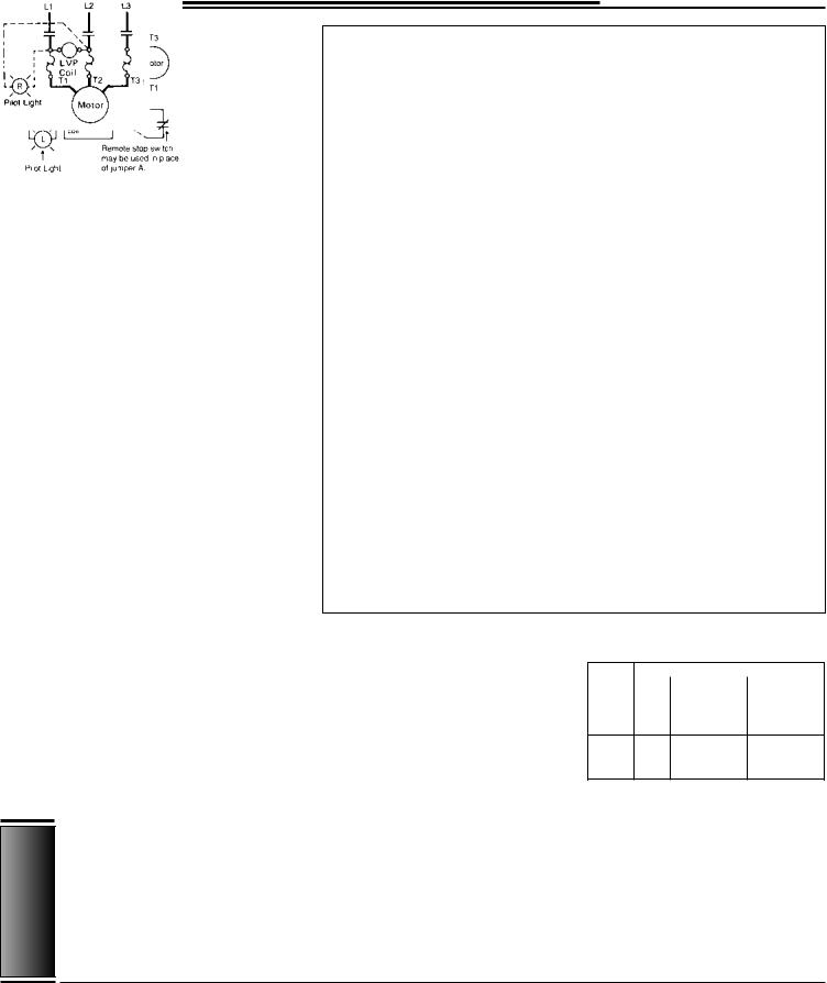
Across the line manual motor starters and contactors provide control for machinery where start stop remote control is not required (optional remote stop available). Class 11 manual starters are used for single and polyphase motors up to 10 Hp. Starters have melting alloy overload relays which help protect against damage due to excessive current caused by a sustained overload, low line voltage, or single phasing of the motor.
Contactors provide control for inherently protected motors. Typical applications include metal and wood-working machinery, grinders, power saws, conveyors, fans pumps, blowers, textile and packaging machinery, slitters, and paper cutters.
Features
Class 11 manual controllers have front accessible pressure type wire connectors. Ample wiring space is provided for easy wiring.
A complete line of general purpose and industrial duty enclosures is available as well as open type mounting for custom built enclosures. These manual controllers are available with low voltage protection which will automatically open the power poles when the voltage drops or the power is interrupted. A remote stop function may be incorporated with the low voltage protection coil as a factory option to provide remote or semi-auto- matic operation.
Class 11 controllers provide the OSHA requirements for protecting personnel from potential injury caused by the automatic start up of machinery following a voltage drop or power interruption when low voltage protection is specified.
Open styles and devices in NEMA 1, 4, 7 & 9, 12 enclosures can be padlocked in the OFF position.
Table 15.11
Class 11 Manual Motor Starters
|
Maximum Horsepower |
|
|
Type |
Size |
115 Volts |
200/230 Volts |
|
M0 |
1 |
2 |
1-Phase |
M1 |
2 |
3 |
|
M1P |
3 |
5 |
Type |
Size |
200/230 Volts |
460/575 Volts |
|
3-Phase |
M0 |
3 |
5 |
|
M1 |
71⁄2 |
10 |
||
|
290 |
Siemens Electrical Products and Systems |
CSI Section 16160 |
|
Specification Guide |
|||
|
|
AC Controls
Manual Motor Starters and Contactors
Dimensions
Table 15.12 |
Motor Starters |
|
|
|
|
|
|
|
|
|
|
|
||
|
|
|
|
|
|
Mounting |
|
Mtg. |
|
|
Max |
Approx |
|
|
|
|
Outline Dimensions in Inches (mm) |
Dimensions in Inches (mm) |
Screw |
Conduit Size |
|
||||||||
Enclosure |
|
Wire |
Ship Wt |
Ref |
||||||||||
Type |
Fig |
A |
|
B |
C |
D |
|
E |
G |
K1 |
K2 |
Size |
Lbs |
Dwg |
Open |
1 |
5.313 |
(134.94) |
2.500 ( 63.50) |
3.625 ( 92.08) |
5.500 |
(139.70) |
2.250 ( 57.15) |
10 |
— |
— |
8 |
3 |
D54755 |
NEMA 1 |
2 |
8.000 |
(203.20) |
5.688 (114.46) |
3.188 ( 80.96) |
5.875 |
(149.23) |
2.500 ( 63.50) |
10 |
1/2 – 3/4 |
— |
8 |
8 |
D25055 |
NEMA 4 |
3 |
11.875 |
(301.63) |
6.250 (158.75) |
5.125 (130.18) |
10.375 |
(263.53) |
4.125 (104.78) |
1/4 |
— |
— |
8 |
10 |
D54824 |
NEMA 4X |
4 |
11.875 |
(301.63) |
7.938 (201.62) |
7.313 (185.74) |
11.125 |
(282.58) |
6.875 (174.63) |
10 |
1 |
— |
8 |
12 |
D26243 |
NEMA 7 & 9 |
5 |
11.000 |
(279.40) |
7.125 (184.15) |
5.875 (149.23) |
9.188 |
(233.36) |
6.063 (153.99) |
1/2 |
1/2 |
3/4 |
8 |
27 |
D56049 |
NEMA 12 |
6 |
9.700 |
(233.36) |
5.875 (149.23) |
5.063 (128.59) |
8.625 |
(219.08) |
3.000 ( 76.20) |
— |
— |
— |
8 |
11 |
D25293 |
Figure 1
Figure 2 |
|
Figure 3 |
|
|
|
|
|
|
|
|
|
Figure 4 |
|
Figure 5 |
|
Figure 6 |
15
Controls AC
CSI Section 16160 |
Siemens Electrical Products and Systems |
291 |
|
Specification Guide |
|
AC Controls
Magnetic Contactors
General
Applications
Class 40 industrial magnetic contactors are designed for electrical loads such as heating, lighting, transformer and capacitor switching, and AC motor starting.
They control motors already protected by inherent or other types of overload devices. Used with appropriate pilot control, a contactor provides a choice of undervoltage protection or release.
Class 40 contactors Size 0 thru 6 feature carefully wound coils encapsulated to seal out moisture. Encapsulation also promotes heat transfer and resists electrical, mechanical, and thermal stresses.
Features
Horsepower rated contactors are available in NEMA sizes 00 through 6, plus four Siemens Furnas Half Sizes: 13⁄4, 21⁄2, 31⁄2, and 41⁄2. These contactors are available as an open type or in NEMA 1, 3, 4, 4X, 7 & 9, or 12 enclosures. These contactors can also be used on capacitor and transformer switching applications.
Resistance heating contactors are available in 11 sizes from 10 through 350 amperes in 2- and 3-pole models and in 4 sizes in 4-pole models.
Lighting contactors are available in 11 sizes from 20 through 600 amperes in 2- and 3-pole models and in 3 sizes in 4- pole models. Lighting contactors are especially designed to switch ballast type, tungsten, and other discharge type lighting loads. These contactors may be controlled by timers and other pilot devices.
These contactors are also available with a DC coil and rectifier for reduction of AC hum in noise-sensitive areas such as hospitals, schools, and similar locations.
For information and availability of mechanically held lighting contactors, contact your local sales office.
Compact Lighting Contactor Size 0–13/4
Table 15.13 |
Coil Data |
|
|
|
|
|
|
|
|
||
|
|
|
|
|
|
|
Inrush |
|
|
Normal |
|
Class |
|
|
|
|
|
Volts |
(Open Magnet) |
|
(Sealed Magnet) |
||
Size |
Watts |
|
|
60Hz |
Amps |
VA |
|
Amps |
VA |
||
|
|
|
|
24 |
2.63 |
|
0.37 |
|
|||
|
|
|
|
120 |
0.59 |
|
0.08 |
|
|||
|
13.3 |
|
|
208 |
0.34 |
70 |
0.05 |
10 |
|||
00 |
|
|
|
|
240 |
0.305 |
0.045 |
||||
|
|
|
|
277 |
0.25 |
|
|
0.03 |
|
||
|
|
|
|
|
|
480 |
1.49 |
|
0.02 |
|
|
|
|
|
|
600 |
0.121 |
|
0.02 |
|
|||
|
|
|
|
24 |
9.08 |
|
1.04 |
|
|||
|
|
|
|
120 |
1.82 |
|
0.21 |
|
|||
0 |
8.6 |
|
|
|
|
208 |
1.05 |
218 |
0.12 |
25 |
|
thru |
|
|
240 |
0.91 |
0.105 |
||||||
21/2 |
|
|
|
277 |
0.79 |
|
0.090 |
|
|||
|
|
|
|
|
|
480 |
0.45 |
|
0.052 |
|
|
|
|
|
|
600 |
0.36 |
|
0.042 |
|
|||
|
|
|
|
24 |
12.90 |
|
1.08 |
|
|||
|
|
|
|
120 |
2.58 |
|
|
0.217 |
|
||
|
14 |
|
|
208 |
1.49 |
310 |
|
0.125 |
26 |
||
3, 31/2 |
|
|
|
|
240 |
1.29 |
0.108 |
||||
|
|
|
|
277 |
1.12 |
|
0.094 |
|
|||
|
|
|
|
|
|
480 |
0.646 |
|
0.054 |
|
|
|
|
|
|
600 |
0.516 |
|
0.043 |
|
|||
|
|
|
|
120 |
4.25 |
|
0.425 |
|
|||
|
|
|
|
|
|
208 |
2.45 |
|
0.245 |
|
|
4 |
22 |
|
|
|
|
240 |
2.14 |
510 |
0.215 |
51 |
|
|
|
277 |
1.77 |
0.183 |
|||||||
|
|
|
|
|
|
||||||
|
|
|
|
|
|
480 |
1.08 |
|
0.112 |
|
|
|
|
|
|
600 |
0.85 |
|
|
0.085 |
|
||
|
|
|
|
120 |
12.65 |
|
0.96 |
|
|||
41/2, 5 |
63 |
|
|
240 |
6.32 |
1518 |
0.48 |
116 |
|||
|
|
480 |
3.16 |
0.24 |
|||||||
|
|
|
|
|
|
||||||
|
|
|
|
600 |
2.53 |
|
|
0.193 |
|
||
|
|
|
|
240 |
1.45 |
|
0.25 |
|
|||
6 |
40 |
|
|
480 |
0.73 |
350 |
|
0.12 |
60 |
||
|
|
|
|
|
600 |
0.58 |
|
0.10 |
|
||
Table 15.14 Reference Literature
15
AC Controls
Instruction Sheets and Replacement Parts
|
NEMA |
|
Motor Matched |
|
|
|
Size |
|
Half Size |
Instruction Sheet |
Replacement Parts |
00 |
|
— |
PM-60.1 |
14-GBG |
|
0-1 |
|
13/4 |
PM-60.1 |
14-GEP |
|
2 |
|
21/2 |
PM-60.1 |
14-GFP |
|
|
3 |
|
31/2 |
PM-60.1 |
14-GHP |
4 |
|
|
PM-60.1 |
14-GJG |
|
5 |
|
41/2 |
PM-60.1 |
14-GKF-B |
|
|
6 |
|
|
PM-60.1 |
14-GMF-B |
|
Class 21 Lighting Contractor |
|
|
21-GWE |
|
|
Competitive Product Comparison |
|
|
|
|
|
Size 1 Starters 14-PC2 |
|
|
|
|
Furnas The Right Choice Form 1485
Specifying a NEMA Rated Starter Form 1555
292 |
Siemens Electrical Products and Systems |
CSI Section 16160 |
|
Specification Guide |
|||
|
|
Loading...