


 Loading...
HP Compaq Business PC Maintenance
and Service Guide
Pro 6300 Series Microtower
Pro 6300 Series Small Form Factor
© Copyright 2012 Hewlett-Packard Development Company, L.P. The information contained herein is subject to change without notice.
Microsoft, Windows, and Windows Vista are either trademarks or registered trademarks of Microsoft Corporation in the United States and/or other countries.
The only warranties for HP products and services are set forth in the express warranty statements accompanying such products and services. Nothing herein should be construed as constituting an additional warranty. HP shall not be liable for technical or editorial errors or omissions contained herein.
This document contains proprietary information that is protected by copyright. No part of this document may be photocopied, reproduced, or translated to another language without the prior written consent of Hewlett-Packard Company.
Second Edition (December 2012)
First Edition (June 2012)
Document Part Number: 690362-002

About This Book
WARNING! Text set off in this manner indicates that failure to follow directions could result in bodily harm or loss of life.
CAUTION: Text set off in this manner indicates that failure to follow directions could result in damage to equipment or loss of information.
 NOTE: Text set off in this manner provides important supplemental information.
iii

Table of contents
1 Product Features ............................................................................................................................................ |
1 |
Standard Configuration Features ......................................................................................................... |
1 |
Microtower (MT) Front Panel Components .......................................................................................... |
2 |
Small Form Factor (SFF) Front Panel Components ............................................................................. |
3 |
Microtower (MT) Rear Panel Components ........................................................................................... |
4 |
Small Form Factor (SFF) Rear Panel Components ............................................................................. |
5 |
Serial Number Location ........................................................................................................................ |
6 |
2 Activating and Customizing the Software .................................................................................................... |
7 |
Activating and customizing the software in Windows 7 ........................................................................ |
7 |
Activating the Windows operating system ........................................................................... |
7 |
Downloading Windows 7 updates ........................................................................................ |
8 |
Installing or upgrading device drivers .................................................................................. |
8 |
Customizing the monitor display .......................................................................................... |
8 |
Activating and customizing the software in Windows 8 ........................................................................ |
8 |
Activating the Windows Operating System .......................................................................... |
8 |
Downloading Windows 8 updates ........................................................................................ |
9 |
Customizing the monitor display .......................................................................................... |
9 |
3 Computer Setup (F10) Utility ....................................................................................................................... |
10 |
Computer Setup (F10) Utilities ........................................................................................................... |
10 |
Using Computer Setup (F10) Utilities ................................................................................ |
11 |
Computer Setup—File ....................................................................................................... |
12 |
Computer Setup—Storage ................................................................................................ |
13 |
Computer Setup—Security ................................................................................................ |
16 |
Computer Setup—Power ................................................................................................... |
21 |
Computer Setup—Advanced ............................................................................................. |
22 |
Recovering the Configuration Settings ............................................................................................... |
24 |
4 Illustrated parts catalog ............................................................................................................................... |
25 |
Microtower (MT) chassis spare parts ................................................................................................. |
25 |
v
Computer major components ............................................................................................ |
25 |
Cables ................................................................................................................................ |
27 |
Misc parts .......................................................................................................................... |
28 |
Drives ................................................................................................................................. |
30 |
Misc boards ....................................................................................................................... |
30 |
Sequential part number listing ........................................................................................... |
31 |
Small Form Factor (SFF) chassis spare parts .................................................................................... |
35 |
Computer major components ............................................................................................ |
35 |
Cables ................................................................................................................................ |
37 |
Misc parts .......................................................................................................................... |
38 |
Drives ................................................................................................................................. |
40 |
Misc boards ....................................................................................................................... |
40 |
Sequential part number listing ........................................................................................... |
41 |
5 Routine Care, SATA Drive Guidelines, and Disassembly Preparation .................................................... |
45 |
Electrostatic Discharge Information .................................................................................................... |
45 |
Generating Static ............................................................................................................... |
45 |
Preventing Electrostatic Damage to Equipment ................................................................ |
46 |
Personal Grounding Methods and Equipment ................................................................... |
46 |
Grounding the Work Area .................................................................................................. |
47 |
Recommended Materials and Equipment .......................................................................... |
47 |
Operating Guidelines .......................................................................................................................... |
48 |
Routine Care ...................................................................................................................................... |
48 |
General Cleaning Safety Precautions ................................................................................ |
48 |
Cleaning the Computer Case ............................................................................................ |
48 |
Cleaning the Keyboard ...................................................................................................... |
49 |
Cleaning the Monitor .......................................................................................................... |
49 |
Cleaning the Mouse ........................................................................................................... |
50 |
Service Considerations ...................................................................................................................... |
50 |
Power Supply Fan ............................................................................................................. |
50 |
Tools and Software Requirements .................................................................................... |
50 |
Screws ............................................................................................................................... |
50 |
Cables and Connectors ..................................................................................................... |
51 |
Hard Drives ........................................................................................................................ |
51 |
Lithium Coin Cell Battery ................................................................................................... |
51 |
SATA Hard Drives .............................................................................................................................. |
52 |
SATA Hard Drive Cables .................................................................................................................... |
52 |
SATA Data Cable .............................................................................................................. |
52 |
SMART ATA Drives ............................................................................................................................ |
52 |
Cable Management ............................................................................................................................ |
52 |
vi
6 Removal and Replacement Procedures Microtower (MT) Chassis .......................................................... |
54 |
Preparation for Disassembly .............................................................................................................. |
54 |
Computer Access Panel ..................................................................................................................... |
55 |
Front Bezel ......................................................................................................................................... |
56 |
Front Bezel Security ........................................................................................................................... |
57 |
Bezel Blanks ....................................................................................................................................... |
59 |
Memory .............................................................................................................................................. |
60 |
DIMMs ............................................................................................................................... |
60 |
DDR3-SDRAM DIMMs ...................................................................................................... |
60 |
Populating DIMM Sockets ................................................................................................. |
60 |
Installing DIMMs ................................................................................................................ |
61 |
Expansion Cards ................................................................................................................................ |
63 |
System Board Connections ................................................................................................................ |
67 |
Drives ................................................................................................................................................. |
68 |
Drive Positions ................................................................................................................... |
70 |
Removing a 5.25-inch or 3.5-inch Drive from a Drive Bay ................................................. |
71 |
Installing a 5.25-inch or 3.5-inch Drive into a Drive Bay .................................................... |
72 |
Removing a Hard Drive from a Drive Bay .......................................................................... |
75 |
Installing a Hard Drive into an Internal Drive Bay .............................................................. |
75 |
Front Fan Assembly ........................................................................................................................... |
79 |
Front I/O Assembly ............................................................................................................................. |
81 |
Power Switch/LED Assembly ............................................................................................................. |
82 |
Heat sink ............................................................................................................................................ |
83 |
Processor ........................................................................................................................................... |
85 |
Speaker .............................................................................................................................................. |
88 |
Rear Chassis Fan ............................................................................................................................... |
89 |
Power Supply ..................................................................................................................................... |
91 |
System Board ..................................................................................................................................... |
93 |
7 Removal and Replacement Procedures Small Form Factor (SFF) Chassis ............................................ |
94 |
Preparation for Disassembly .............................................................................................................. |
94 |
Access Panel ...................................................................................................................................... |
95 |
Front Bezel ......................................................................................................................................... |
96 |
Front Bezel Security ........................................................................................................................... |
97 |
Bezel Blanks ....................................................................................................................................... |
99 |
Memory ............................................................................................................................................ |
100 |
DIMMs ............................................................................................................................. |
100 |
DDR3-SDRAM DIMMs .................................................................................................... |
100 |
Populating DIMM Sockets ............................................................................................... |
100 |
Installing DIMMs .............................................................................................................. |
101 |
Expansion Card ................................................................................................................................ |
103 |
vii
System Board Connections .............................................................................................................. |
107 |
Drives ............................................................................................................................................... |
108 |
Drive Positions ................................................................................................................. |
109 |
Installing and Removing Drives ....................................................................................... |
109 |
Removing a 5.25-inch Drive from a Drive Bay ................................................ |
110 |
Installing a 5.25-inch Drive into a Drive Bay ................................................... |
111 |
Removing a 3.5-inch Drive from a Drive Bay .................................................. |
114 |
Installing a 3.5-inch Drive into a Drive Bay ..................................................... |
115 |
Removing and Replacing the Primary 3.5-inch Internal Hard Drive ................ |
116 |
Fan duct ........................................................................................................................................... |
119 |
Front Fan Assembly ......................................................................................................................... |
120 |
Hood Sensor .................................................................................................................................... |
122 |
Front I/O, Power Switch Assembly ................................................................................................... |
123 |
Speaker ............................................................................................................................................ |
125 |
Heat sink .......................................................................................................................................... |
126 |
Processor ......................................................................................................................................... |
128 |
Power Supply ................................................................................................................................... |
131 |
System Board ................................................................................................................................... |
133 |
Using the Small Form Factor Computer in a Tower Orientation ...................................................... |
135 |
8 Troubleshooting Without Diagnostics ...................................................................................................... |
136 |
Safety and Comfort .......................................................................................................................... |
136 |
Before You Call for Technical Support ............................................................................................. |
136 |
Helpful Hints ..................................................................................................................................... |
137 |
Solving General Problems ................................................................................................................ |
139 |
Solving Power Problems .................................................................................................................. |
143 |
Solving Hard Drive Problems ........................................................................................................... |
145 |
Solving Media Card Reader Problems ............................................................................................. |
148 |
Solving Display Problems ................................................................................................................. |
150 |
Solving Audio Problems ................................................................................................................... |
155 |
Solving Printer Problems .................................................................................................................. |
157 |
Solving Keyboard and Mouse Problems .......................................................................................... |
159 |
Solving Hardware Installation Problems ........................................................................................... |
161 |
Solving Network Problems ............................................................................................................... |
163 |
Solving Memory Problems ............................................................................................................... |
166 |
Solving Processor Problems ............................................................................................................ |
168 |
Solving CD-ROM and DVD Problems .............................................................................................. |
168 |
Solving USB Flash Drive Problems .................................................................................................. |
170 |
Solving Front Panel Component Problems ...................................................................................... |
172 |
Solving Internet Access Problems .................................................................................................... |
172 |
Solving Software Problems .............................................................................................................. |
174 |
viii
Contacting Customer Support .......................................................................................................... |
176 |
9 POST Error Messages ................................................................................................................................ |
177 |
POST Numeric Codes and Text Messages ..................................................................................... |
178 |
Interpreting POST Diagnostic Front Panel LEDs and Audible Codes .............................................. |
186 |
10 Password Security and Resetting CMOS ............................................................................................... |
190 |
Resetting the Password Jumper ...................................................................................................... |
191 |
Clearing and Resetting the CMOS ................................................................................................... |
192 |
11 HP PC Hardware Diagnostics .................................................................................................................. |
194 |
Why run HP PC Hardware Diagnostics – UEFI ................................................................................ |
194 |
How to access and run HP PC Hardware Diagnostics - UEFI ......................................................... |
194 |
Downloading HP PC Hardware Diagnostics to a USB device .......................................................... |
195 |
12 Backup and Recovery .............................................................................................................................. |
196 |
Restoring and recovering in Windows 7 ........................................................................................... |
196 |
System Restore ............................................................................................................... |
196 |
System Recovery ............................................................................................................. |
196 |
System Recovery when Windows is responding ............................................ |
197 |
System Recovery when Windows is not responding ...................................... |
198 |
System recovery using recovery media .......................................................... |
198 |
Creating recovery media ................................................................ |
199 |
Using recovery media ..................................................................... |
200 |
Backup and recovery in Windows 8 ................................................................................................. |
201 |
Backing up your information ............................................................................................ |
201 |
Performing a system recovery ......................................................................................... |
202 |
Using the Windows recovery tools .................................................................. |
202 |
Using f11 recovery tools .................................................................................. |
203 |
Using Windows 8 operating system media (purchased separately) ............... |
203 |
Appendix A Battery Replacement ................................................................................................................ |
204 |
Appendix B Removing and Replacing a Removable 3.5-inch SATA Hard Drive ..................................... |
207 |
Appendix C Unlocking the Smart Cover Lock ............................................................................................ |
212 |
Smart Cover FailSafe Key ................................................................................................................ |
212 |
Using the Smart Cover FailSafe Key to Remove the Smart Cover Lock ......................................... |
213 |
ix
Appendix D Power Cord Set Requirements ................................................................................................ |
215 |
General Requirements ..................................................................................................................... |
215 |
Japanese Power Cord Requirements .............................................................................................. |
215 |
Country-Specific Requirements ........................................................................................................ |
216 |
Appendix E Specifications ............................................................................................................................ |
217 |
MT Specifications ............................................................................................................................. |
217 |
SFF Specifications ........................................................................................................................... |
219 |
Index ................................................................................................................................................................. |
220 |
x

1 Product Features
Standard Configuration Features
Features may vary depending on the model. For a complete listing of the hardware and software installed in the computer, run the diagnostic utility (included on some computer models only).
Figure 1-1 Microtower Configuration
Figure 1-2 Small Form Factor Configuration
Standard Configuration Features |
1 |


 NOTE: The Small Form Factor computer can also be used in a tower orientation. For more information, see Using the Small Form Factor Computer in a Tower Orientation on page 135 in this guide.
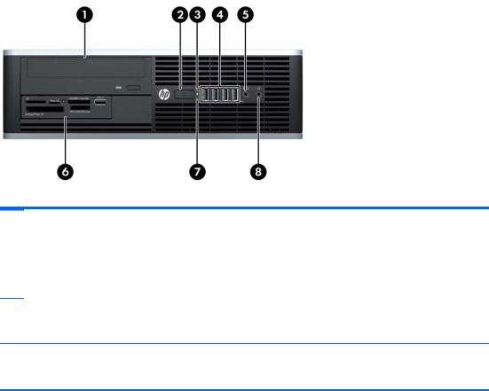
Microtower (MT) Front Panel Components
Drive configuration may vary by model. Some models have a bezel blank covering one or more drive bays.
Table 1-1 Front Panel Components
1 |
5.25-inch Optical Drives |
5 |
3.5-inch Media Card Reader (optional) |
|
|
|
|
2 |
Hard Drive Activity Light |
6 |
Dual-State Power Button |
|
|
|
|
3 |
Microphone/Headphone Connector |
7 |
Power On Light |
|
|
|
|
4 |
USB (Universal Serial Bus) 2.0 Ports |
8 |
Headphone Connector |
NOTE: When a device is plugged into the Microphone/Headphone Connector, a dialog box will pop up asking if you want to use the connector for a microphone Line-In device or a headphone. You can reconfigure the connector at any time by double-clicking the Realtek HD Audio Manager icon in the Windows taskbar.
NOTE: The Power On Light is normally green when the power is on. If it is flashing red, there is a problem with the computer and it is displaying a diagnostic code. Refer to Interpreting POST Diagnostic Front Panel LEDs and Audible Codes on page 186 to interpret the code.
2 Chapter 1 Product Features
Small Form Factor (SFF) Front Panel Components
Drive configuration may vary by model. Some models have a bezel blank covering one or more drive bays.
Figure 1-3 Front Panel Components
Table 1-2 Front Panel Components
1 |
5.25-inch Optical Drive |
5 |
Microphone/Headphone Connector |
|
|
|
|
2 |
Dual-State Power Button |
6 |
3.5-inch Media Card Reader (optional) |
|
|
|
|
3 |
Power On Light |
7 |
Hard Drive Activity Light |
|
|
|
|
4 |
USB (Universal Serial Bus) Ports |
8 |
Headphone Connector |
NOTE: When a device is plugged into the Microphone/Headphone Connector, a dialog box will pop up asking if you want to use the connector for a microphone Line-In device or a headphone. You can reconfigure the connector at any time by double-clicking the Realtek HD Audio Manager icon in the Windows taskbar.
NOTE: The Power On Light is normally green when the power is on. If it is flashing red, there is a problem with the computer and it is displaying a diagnostic code. Refer toInterpreting POST Diagnostic Front Panel LEDs and Audible Codes on page 186 to interpret the code.
Small Form Factor (SFF) Front Panel Components |
3 |
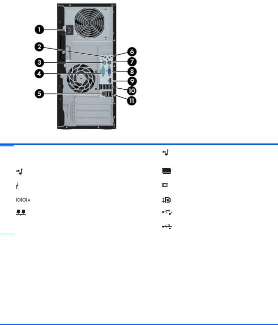
Microtower (MT) Rear Panel Components
Figure 1-4 Rear Panel Components
Table 1-3 Rear Panel Components
1 |
Power Cord Connector |
6 |
Line-Out Connector for powered audio |
|
|
|
devices (green) |
|
|
|
|
2 |
Line-In Audio Connector (blue) |
7 |
PS/2 Keyboard Connector (purple) |
|
|
|
|
3 |
PS/2 Mouse Connector (green) |
8 |
VGA Monitor Connector |
|
|
|
|
4 |
Serial Connector |
9 |
DisplayPort Monitor Connector |
|
|
|
|
5 |
RJ-45 Network Connector |
10 |
USB 3.0 ports (blue) |
|
|
|
|
|
|
11 |
USB 2.0 ports (black) |
NOTE: USB 3.0 ports are blue; USB 2.0 ports are black.
An optional second serial port and an optional parallel port are available from HP.
When a device is plugged into the blue Line-In Audio Connector, a dialog box will pop up asking if you want to use the connector for a line-in device or a microphone. You can reconfigure the connector at any time by doubleclicking the Realtek HD Audio Manager icon in the Windows taskbar.
The monitor connectors on the system board are inactive when a graphics card is installed in the computer.
If a graphics card is installed into one of the motherboard slots, the connectors on the graphics card and the system board may be used at the same time. Some settings may need to be changed in Computer Setup to use both connectors.
4 Chapter 1 Product Features
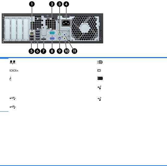
Small Form Factor (SFF) Rear Panel Components
Figure 1-5 Rear Panel Components
1 |
RJ-45 Network Connector |
7 |
DisplayPort Monitor Connector |
|
|
|
|
2 |
Serial Connector |
8 |
VGA Monitor Connector |
|
|
|
|
3 |
PS/2 Mouse Connector (green) |
9 |
PS/2 Keyboard Connector (purple) |
|
|
|
|
4 |
Power Cord Connector |
10 |
Line-Out Connector for powered audio |
|
|
|
devices (green) |
|
|
|
|
5 |
USB 2.0 ports (black) |
11 |
Line-In Audio Connector (blue) |
|
|
|
|
6 |
USB 3.0 ports (blue) |
|
|
NOTE: USB 3.0 ports are blue; USB 2.0 ports are black.
An optional second serial port and an optional parallel port are available from HP.
When a device is plugged into the blue Line-In Audio Connector, a dialog box will pop up asking if you want to use the connector for a line-in device or a microphone. You can reconfigure the connector at any time by doubleclicking the Realtek HD Audio Manager icon in the Windows taskbar.
The monitor connectors on the system board are inactive when a graphics card is installed in the computer.
If a graphics card is installed into one of the motherboard slots, the connectors on the graphics card and the system board may be used at the same time. Some settings may need to be changed in Computer Setup to use both connectors.
Small Form Factor (SFF) Rear Panel Components |
5 |
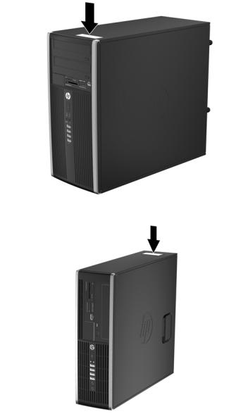
Serial Number Location
Each computer has a unique serial number and a product ID number that are located on the top cover of the computer. Keep these numbers available for use when contacting customer service for assistance.
Figure 1-6 Microtower Serial Number and Product ID Location
Figure 1-7 Small Form Factor Serial Number and Product ID Location
6 Chapter 1 Product Features

2Activating and Customizing the Software
 NOTE: This chapter provides information for both Windows 7 and Windows 8.
Activating and customizing the software in Windows 7
If your computer was not shipped with a Windows® operating system, some portions of this documentation do not apply. Additional information is available in online help after you activate the operating system.
CAUTION: Do not add optional hardware or third-party devices to the computer until the operating system is successfully activated. Doing so may cause errors and prevent the operating system from installing properly.


 NOTE: Be sure there is a 10.2 cm (4 inch) clearance at the back of the unit and above the monitor to permit the required airflow.
Activating the Windows operating system
The first time you turn on the computer, the operating system is set up and activated automatically. This process takes about 5 to 10 minutes. Carefully read and follow the instructions on the screen to complete the activation.
We recommend that you register your computer with HP during operating system setup so you can receive important software updates, facilitate support questions, and sign up for special offers.
CAUTION: After the activation process has begun, DO NOT TURN OFF THE COMPUTER UNTIL THE PROCESS IS COMPLETE. Turning off the computer during the activation process may damage the software that runs the computer or prevent its proper installation.


 NOTE: If the computer shipped with more than one operating system language on the hard drive, the activation process could take up to 60 minutes.
Activating and customizing the software in Windows 7 |
7 |

Downloading Windows 7 updates
Microsoft may release updates to the operating system. To help keep the computer running optimally, HP recommends checking for the latest updates during the initial installation and periodically throughout the life of the computer.
1.To set up your Internet connection, click Start > Internet Explorer and follow the instructions on the screen.
2.After an Internet connection has been established, click the Start > All Programs > Windows Update.
3.Run Windows Update monthly thereafter.
Installing or upgrading device drivers
When installing optional hardware devices after the operating system installation is complete, you must also install the drivers for each of the devices.
In Windows 7, if prompted for the i386 directory, replace the path specification with C:\i386, or use the Browse button in the dialog box to locate the i386 folder. This action points the operating system to the appropriate drivers.
Obtain the latest support software, including support software for the operating system, from http://www.hp.com/support. Select your country and language, select Download drivers and software (and firmware), enter the model number of the computer, and press Enter.
Customizing the monitor display
If you wish, you can select or change the monitor refresh rates, screen resolution, color settings, font sizes, and power management settings.
For more information, refer to the online documentation provided with the graphics controller utility or the documentation that came with your monitor.
Right-click on the Windows desktop, then click Personalize to change display settings.
Activating and customizing the software in Windows 8
Additional information is available in online help after you activate the operating system.


 NOTE: Be sure there is a 10.2 cm (4 inch) clearance at the back of the unit and above the monitor to permit the required airflow.
Activating the Windows Operating System
The first time you turn on the computer, the operating system is set up and activated automatically. This process takes about 5 to 10 minutes. Carefully read and follow the instructions on the screen to complete the activation.
We recommend that you register your computer with HP during operating system set up so you can receive important software updates, facilitate support questions, and sign up for special offers. You can also register your computer with HP using the Register with HP app on the Start screen.
8 |
Chapter 2 Activating and Customizing the Software |

CAUTION: After the activation process has begun, DO NOT TURN OFF THE COMPUTER UNTIL THE PROCESS IS COMPLETE. Turning off the computer during the activation process may damage the software that runs the computer or prevent its proper installation.
Downloading Windows 8 updates
Microsoft may release updates to the operating system. To help keep the computer running optimally, HP recommends checking for the latest updates during the initial installation and periodically throughout the life of the computer.
Run Windows Update as soon as possible after you set up your computer.
1.Point to the upper-right or lower-right corner of the Start screen to display the charms.
2.Click Settings > Change PC Settings > Windows Update.
3.Run Windows Update monthly thereafter.
Customizing the monitor display
You can customize display settings for Windows 8 separately for the Start screen and the Desktop.
To customize the Start screen:
1.Point to the upper-right or lower-right corner of the Start screen to display the charms.
2.Click Settings > Change PC Settings.
3.Click Personalize to change the display settings.
To customize the Desktop:
1.Click the Desktop app on the Start screen.
2.Right-click on the desktop, and then click Personalize to change display settings.
Activating and customizing the software in Windows 8 |
9 |

3 Computer Setup (F10) Utility
Computer Setup (F10) Utilities
Use Computer Setup (F10) Utility to do the following:
●Change factory default settings.
●Set the system date and time.
●Set, view, change, or verify the system configuration, including settings for processor, graphics, memory, audio, storage, communications, and input devices.
●Modify the boot order of bootable devices such as hard drives, optical drives, or USB flash media devices.
●Enable Quick Boot, which is faster than Full Boot but does not run all of the diagnostic tests run during a Full Boot. You can set the system to:
always Quick Boot (default);
periodically Full Boot (from every 1 to 30 days); or
always Full Boot.
●Select Post Messages Enabled or Disabled to change the display status of Power-On Self-Test (POST) messages. Post Messages Disabled suppresses most POST messages, such as memory count, product name, and other non-error text messages. If a POST error occurs, the error is displayed regardless of the mode selected. To manually switch to Post Messages Enabled during POST, press any key (except F1 through F12).
●Establish an Ownership Tag, the text of which is displayed each time the system is turned on or restarted.
●Enter the Asset Tag or property identification number assigned by the company to this computer.
●Enable the power-on password prompt during system restarts (warm boots) as well as during power-on.
●Establish a setup password that controls access to the Computer Setup (F10) Utility and the settings described in this section.
●Secure integrated I/O functionality, including the serial, USB, or parallel ports, audio, or embedded NIC, so that they cannot be used until they are unsecured.
●Enable or disable removable media boot ability.
10 Chapter 3 Computer Setup (F10) Utility

●Solve system configuration errors detected but not automatically fixed during the Power-On SelfTest (POST).
●Replicate the system setup by saving system configuration information on a USB device and restoring it on one or more computers.
●Execute self-tests on a specified ATA hard drive (when supported by drive).
●Enable or disable DriveLock security (when supported by drive).
Using Computer Setup (F10) Utilities
Computer Setup can be accessed only by turning the computer on or restarting the system. To access the Computer Setup Utilities menu, complete the following steps:
1.Turn on or restart the computer.
2.Repeatedly press F10 when the monitor light turns green to access the utility.
You can also press Esc to a menu that allows you to access different options available at startup, including the Computer Setup utility.


 NOTE: If you do not press F10 at the appropriate time, you must restart the computer and again repeatedly press F10 when the monitor light turns green to access the utility.
3.A choice of five headings appears in the Computer Setup Utilities menu: File, Storage, Security, Power, and Advanced.
4.Use the arrow (left and right) keys to select the appropriate heading. Use the arrow (up and down) keys to select the option you want, then press Enter. To return to the Computer Setup Utilities menu, press Esc.
5.To apply and save changes, select File > Save Changes and Exit.
●If you have made changes that you do not want applied, select Ignore Changes and Exit.
●To reset to factory settings or previously saved default settings (some models), select Apply Defaults and Exit. This option will restore the original factory system defaults.
 NOTE: Not all settings shown in the following sections are available for all models
CAUTION: Do NOT turn the computer power OFF while the BIOS is saving the Computer Setup (F10) changes because the CMOS could become corrupted. It is safe to turn off the computer only after exiting the F10 Setup screen.
Table 3-1 Computer Setup (F10) Utility
Heading |
Table |
|
|
File |
Computer Setup—File on page 12 |
|
|
Storage |
Computer Setup—Storage on page 13 |
|
|
Security |
Computer Setup—Security on page 16 |
|
|
Power |
Computer Setup—Power on page 21 |
|
|
Advanced |
Computer Setup—Advanced on page 22 |
|
|
Computer Setup (F10) Utilities 11
Computer Setup—File


 NOTE: Support for specific Computer Setup options may vary depending on the hardware configuration.
Table 3-2 Computer Setup—File
Option |
Description |
|
|
|
|
System Information |
Lists: |
|
|
● |
Product name |
|
● |
SKU number |
|
● |
Processor type/speed/stepping |
|
● Cache size (L1/L2/L3) (dual core processors have this listed twice) |
|
|
● Installed memory size/speed, number of channels (single or dual) (if applicable) |
|
|
● Integrated MAC address for embedded, enabled NIC (if applicable) |
|
|
● System BIOS (includes family name and version) |
|
|
● |
Chassis serial number |
|
● |
Asset tracking number |
|
● |
ME firmware version |
|
● |
ME Management mode |
|
|
|
About |
Displays copyright notice. |
|
|
|
|
Set Time and Date |
Allows you to set system time and date. |
|
|
|
|
Flash System ROM |
Allows you to update the system ROM with a BIOS image file located on removable media. |
|
|
|
|
Replicated Setup |
Save to Removable Media |
|
|
Saves system configuration to a formatted USB flash media device. |
|
|
Restore from Removable Media |
|
|
Restores system configuration from a USB flash media device. |
|
|
|
|
Default Setup |
Save Current Settings as Default |
|
|
Saves the current system configuration settings as the default. |
|
|
Restore Factory Settings as Default |
|
|
Restores the factory system configuration settings as the default. |
|
|
|
|
Apply Defaults and |
Applies the currently selected default settings and clears any established passwords. |
|
Exit |
|
|
|
|
|
Ignore Changes |
Exits Computer Setup without applying or saving any changes. |
|
and Exit |
|
|
|
|
|
Save Changes and |
Saves changes to system configuration or default settings and exits Computer Setup. |
|
Exit |
|
|
|
|
|
12 Chapter 3 Computer Setup (F10) Utility

Computer Setup—Storage


 NOTE: Support for specific Computer Setup options may vary depending on the hardware configuration.
Table 3-3 Computer Setup—Storage
Option |
Description |
Device Configuration Lists all installed BIOS-controlled storage devices.
When a device is selected, detailed information and options are displayed. The following options may be presented:
●Hard Disk: Size, model, firmware version, serial number, connector color.
Translation mode (ATA disks only)
Lets you select the translation mode to be used for the device. This enables the BIOS to access disks partitioned and formatted on other systems and may be necessary for users of older versions of UNIX (e.g., SCO UNIX version 3.2). Options are Automatic, Bit-Shift,
LBA Assisted, User, and Off.
Available only when the drive translation mode is set to User, allows you to specify the parameters (logical cylinders, heads, and sectors per track) used by the BIOS to translate disk I/O requests (from the operating system or an application) into terms the hard drive can accept. Logical cylinders may not exceed 1024. The number of heads may not exceed 256. The number of sectors per track may not exceed 63.
CAUTION: Ordinarily, the translation mode selected automatically by the BIOS should not be changed. If the selected translation mode is not compatible with the translation mode that was active when the disk was partitioned and formatted, the data on the disk will be inaccessible.
●CD-ROM: Model, firmware version, serial number, connector color (not included for USB CDROM).
●SSD Life Used
NOTE: Displays for solid-state drives.
●SMART (ATA disks only)
●Diskette: Model and firmware version.
NOTE: Displays for USB diskette drives.
●Default Values (ATA disks only)
See Translation Mode above for details.
SATA Defaults
Computer Setup (F10) Utilities 13

Table 3-3 Computer Setup—Storage (continued)
Storage Options |
eSATA Port |
|
Allows you to set a SATA port as an eSATA port for use with an external drive. Default is enabled. |
|
This setting affects only the port with the black connector, labeled as eSATA on the system board. |
|
This port should have the eSATA back panel connector attached to use eSATA drives. For more |
|
information, see the eSATA white paper at www.hp.com. |
|
SATA Emulation |
|
Allows you to choose how the SATA controller and devices are accessed by the operating |
|
system. There are three supported options: IDE, RAID, and AHCI (default). |
|
CAUTION: SATA emulation changes may prevent access to existing hard drive data and |
|
degrade or corrupt established volumes. |
|
IDE - This is the most backwards-compatible setting of the three options. Operating systems |
|
usually do not require additional driver support in IDE mode. |
|
RAID - Allows DOS and boot access to RAID volumes. Use this mode with the RAID device driver |
|
loaded in the operating system to take advantage of RAID features. |
|
AHCI (default option) - Allows operating systems with AHCI device drivers loaded to take |
|
advantage of more advanced features of the SATA controller. |
|
NOTE: The RAID/AHCI device driver must be installed prior to attempting to boot from a RAID/ |
|
AHCI volume. If you attempt to boot from a RAID/AHCI volume without the required device driver |
|
installed, the system will crash (blue screen). RAID volumes may become corrupted if they are |
|
booted to after disabling RAID. |
|
Removable Media Boot |
|
Enables/disables ability to boot the system from removable media. Default is enabled. |
|
Max eSATA Speed |
|
Allows you to choose 1.5 Gbps or 3.0 Gpbs as the maximum eSATA speed. By default, the speed |
|
is limited to 1.5 Gbps for maximum reliability. |
|
CAUTION: Consult your eSATA drive and cable manufacturer before enabling 3.0 Gpbs speed. |
|
Some drive and cable combinations may not run reliably at 3.0 Gpbs. |
|
|
14 Chapter 3 Computer Setup (F10) Utility

Table 3-3 Computer Setup—Storage (continued)
DPS Self-Test |
Allows you to execute self-tests on ATA hard drives capable of performing the Drive Protection |
|
System (DPS) self-tests. |
|
NOTE: This selection will only appear when at least one drive capable of performing the DPS |
|
self-tests is attached to the system. |
|
|
Boot Order |
Allows you to: |
|
● EFI Boot Sources: Specify the order in which EFI boot sources (such as a internal hard |
|
drive, USB hard drive, USB optical drive, or internal optical drive) are checked for a bootable |
|
operating system image. Each device on the list may be individually excluded from or |
|
included for consideration as a bootable operating system source. |
|
EFI boot sources always have precedence over legacy boot sources. |
|
● Legacy Boot Sources: Specify the order in which legacy boot sources (such as a network |
|
interface card, internal hard drive, USB optical drive, or internal optical drive) are checked for |
|
a bootable operating system image. Each device on the list may be individually excluded |
|
from or included for consideration as a bootable operating system source. |
|
Specify the order of attached hard drives. The first hard drive in the order will have priority in |
|
the boot sequence and will be recognized as drive C (if any devices are attached). |
|
NOTE: To drag a device to a preferred place, press Enter. To remove the device from |
|
consideration as a bootable device, press F5. |
|
You can use F5 to disable individual boot items, as well as disable EFI boot and/or legacy boot. |
|
NOTE: MS-DOS drive lettering assignments may not apply after a non-MS-DOS operating |
|
system has started. |
|
Shortcut to Temporarily Override Boot Order |
|
To boot one time from a device other than the default device specified in Boot Order, restart the |
|
computer and press Esc (to access the boot menu) and then F9 (Boot Order), or only F9 (skipping |
|
the boot menu) when the monitor light turns green. After POST is completed, a list of bootable |
|
devices is displayed. Use the arrow keys to select the preferred bootable device and press Enter. |
|
The computer then boots from the selected non-default device for this one time. |
|
|
Computer Setup (F10) Utilities 15

Computer Setup—Security


 NOTE: Support for specific Computer Setup options may vary depending on the hardware configuration.
Table 3-4 Computer Setup—Security
Option |
Description |
|
|
Setup Password |
Allows you to set and enable a setup (administrator) password. |
|
NOTE: If the setup password is set, it is required to change Computer Setup options, flash the |
|
ROM, and make changes to certain plug and play settings under Windows. |
|
|
Power-On Password |
Allows you to set and enable a power-on password. The power-on password prompt appears |
|
after a power cycle or reboot. If the user does not enter the correct power-on password, the unit |
|
will not boot. |
|
|
Password Options |
Allows you to enable/disable: |
(This selection appears |
● Lock Legacy Resources (determines whether or not Windows Device Manager is allowed to |
only if a power-on |
change resource settings for serial and parallel ports). |
password or setup |
● Stringent security (enabling the stringent password disables the ability to reset the password |
password is set.) |
|
|
by moving the jumper on the system board). Default is disabled. |
|
CAUTION: If you enable the stringent security feature and you forget the setup password |
|
or the power-on password, the computer is inaccessible and can no longer be used. |
|
If you lose or forget the password, the system board must be replaced. This scenario is not |
|
covered under warranty. |
|
To prevent the computer from becoming permanently unusable, record your configured |
|
setup password or power-on password in a safe place away from your computer. Without |
|
these passwords, the computer cannot be unlocked. |
|
● Setup Browse Mode (appears if a setup password is set) (allows viewing, but not changing, |
|
the F10 Setup Options without entering setup password). Default is enabled. |
|
● Password prompt on F9 & F12 (requires setup password to use these boot functions). |
|
Default is enabled. |
|
● Network Server Mode. Default is disabled. |
|
|
Smart Cover |
Allows you to: |
|
● Lock/unlock the Cover Lock. |
|
● Set the Cover Removal Sensor to Disable/Notify User/Setup Password. |
|
NOTE: Notify User alerts the user that the sensor has detected that the cover has been |
|
removed. Setup Password requires that the setup password be entered to boot the computer if |
|
the sensor detects that the cover has been removed. |
|
|
16 Chapter 3 Computer Setup (F10) Utility

Table 3-4 Computer Setup—Security (continued)
Device Security |
Allows you to set Device Available/Device Hidden (default is Device Available) for: |
|
|
● |
Embedded security device |
|
● |
System audio |
|
● USB controller (varies by model) |
|
|
● |
Network controller |
|
|
NOTE: You must disable AMT before trying to hide the network controller. |
|
● |
Serial port |
|
● |
Parallel port |
|
● SATA ports (varies by model) |
|
|
|
|
USB Security |
Allows you to set Enabled/Disabled (default is Enabled) for: |
|
|
● |
Front USB Ports |
|
● |
Rear USB Ports |
|
● |
Accessory USB Ports |
|
|
|
Slot Security |
Allows you to disable any PCI or PCI Express slot. Default is enabled. |
|
|
|
|
Network Boot |
Enables/disables the computer’s ability to boot from an operating system installed on a network |
|
|
server. (Feature available on NIC models only; the network controller must be either a PCI |
|
|
expansion card or embedded on the system board.) Default is enabled. |
|
|
|
|
System IDs |
Allows you to set: |
|
|
● Asset tag (18-byte identifier), a property identification number assigned by the company to |
|
|
|
the computer. |
● Ownership tag (80-byte identifier) displayed during POST.
● Universal Unique Identifier (UUID) number. The UUID can only be updated if the current chassis serial number is invalid. (These ID numbers are normally set in the factory and are used to uniquely identify the system.)
● Keyboard locale setting for System ID entry.
Computer Setup (F10) Utilities 17

Table 3-4 Computer Setup—Security (continued)
Master Boot Record Enables/disables Master Boot Record (MBR) security.
Security
The MBR contains information needed to successfully boot from a disk and to access the data stored on the disk. Master Boot Record Security may prevent unintentional or malicious changes to the MBR, such as those caused by some viruses or by the incorrect use of certain disk utilities. It also allows you to recover the "last known good" MBR, should changes to the MBR be detected when the system is restarted.
When MBR Security is enabled, the BIOS prevents any changes being made to the MBR of the current bootable disk while in MS-DOS or Windows Safe Mode.
NOTE: Most operating systems control access to the MBR of the current bootable disk; the
BIOS cannot prevent changes that may occur while the operating system is running.
Restores the backup Master Boot Record to the current bootable disk. Default is disabled.
Only appears if all of the following conditions are true:
●MBR security is enabled
●A backup copy of the MBR has been previously saved
●The current bootable disk is the same disk from which the backup copy was saved
CAUTION: Restoring a previously saved MBR after a disk utility or operating system has modified the MBR, may cause the data on the disk to become inaccessible. Only restore a previously saved MBR if you are confident that the current bootable disk's MBR has been corrupted or infected with a virus.
18 Chapter 3 Computer Setup (F10) Utility

Table 3-4 Computer Setup—Security (continued)
System Security |
Data Execution Prevention (enable/disable) - Helps prevent operating system security breaches. |
(these options are |
Default is enabled. |
hardware dependent) |
SVM CPU Virtualization (enable/disable). Controls the virtualization features of the processor. |
|
|
|
Changing this setting requires turning the computer off and then back on. Default is disabled. |
|
Virtualization Technology (VTx) (enable/disable) - Controls the virtualization features of the |
|
processor. Changing this setting requires turning the computer off and then back on. Default is |
|
disabled. |
|
Virtualization Technology Directed I/O (VTd) (enable/disable) - Controls virtualization DMA |
|
remapping features of the chipset. Changing this setting requires turning the computer off and |
|
then back on. Default is disabled. |
|
Trusted Execution Technology (enable/disable) - Controls the underlying processor and chipset |
|
features needed to support a virtual appliance. Changing this setting requires turning the |
|
computer off and then back on. Default is disabled. To enable this feature you must enable the |
|
following features: |
|
● Embedded Security Device Support |
|
● Virtualization Technology |
|
● Virtualization Technology Directed I/O |
|
Embedded Security Device (enable/disable) - Permits activation and deactivation of the |
|
Embedded Security Device. |
|
NOTE: To configure the Embedded Security Device, a Setup password must be set. |
|
● Reset to Factory Settings (Do not reset/Reset) - Resetting to factory defaults will erase all |
|
security keys and leave the device in a disabled state. Changing this setting requires that |
|
you restart the computer. Default is Do not reset. |
|
CAUTION: The embedded security device is a critical component of many security |
|
schemes. Erasing the security keys will prevent access to data protected by the Embedded |
|
Security Device. Choosing Reset to Factory Settings may result in significant data loss. |
|
● Measure boot variables/devices to PCR1 - Typically, the computer measures the boot path |
|
and saves collected metrics to PCR5 (a register in the Embedded Security Device). Bitlocker |
|
tracks changes to any of these metrics, and forces the user to re-authenticate if it detects |
|
any changes. Enabling this feature lets you set Bitlocker to ignore detected changes to boot |
|
path metrics, thereby avoiding re-authentication issues associated with USB keys inserted in |
|
a port. Default is enabled. |
|
|
System Security |
OS management of Embedded Security Device (enable/disable) - This option allows the user to |
(continued) |
limit OS control of the Embedded Security Device. Default is enabled. This option is automatically |
|
disabled if Trusted Execution Technology is enabled. |
|
● Reset of Embedded Security Device through OS (enable/disable) - This option allows the |
|
user to limit the operating system ability to request a Reset to Factory Settings of the |
|
Embedded Security Device. Default is disabled. |
|
NOTE: To enable this option, a Setup password must be set. |
|
● No PPI provisioning (Windows 8 only) - This option lets you set Windows 8 to bypass the PPI |
|
(Physical Presence Interface) requirement and directly enable and take ownership of the |
|
TPM on first boot. You cannot change this setting after TPM is owned/initialized, unless the |
|
TPM is reset. Default is disabled for non-Windows 8 systems, and enabled for Windows 8. |
|
● Allow PPI policy to be changed by OS. Enabling this option allows the operating system to |
|
execute TPM operations without Physical Presence Interface. Default is disabled. |
|
NOTE: To enable this option, a Setup password must be set. |
|
|
Computer Setup (F10) Utilities 19

Table 3-4 Computer Setup—Security (continued)
DriveLock Security |
Allows you to assign or modify a master or user password for hard drives. When this feature is |
|
|
enabled, the user is prompted to provide one of the DriveLock passwords during POST. If neither |
|
|
is successfully entered, the hard drive will remain inaccessible until one of the passwords is |
|
|
successfully provided during a subsequent cold-boot sequence. |
|
|
NOTE: This selection will only appear when at least one drive that supports the DriveLock |
|
|
feature is attached to the system. |
|
|
|
|
Secure Boot |
This is a feature of Windows 8. |
|
Configuration |
● Legacy Support—Enable/Disable. Allows you to turn off all legacy support on the computer, |
|
|
||
|
including booting to DOS, running legacy graphics cards, booting to legacy devices, and so |
|
|
on. If set to disable, legacy boot options in Storage > Boot Order are not displayed. Default |
|
|
is enabled. |
|
|
● Secure Boot—Enable/Disable. Allows you to make sure an operating system is legitimate |
|
|
before booting to it, making Windows resistant to malicious modification from preboot to full |
|
|
OS booting, preventing firmware attacks. UEFI and Windows Secure Boot only allow code |
|
|
signed by pre-approved digital certificates to run during the firmware and OS boot process. |
|
|
Default is disabled, except for Windows 8 systems which have this setting enabled. Secure |
|
|
Boot enabled also sets Legacy Support to disabled. |
|
|
● Key Management—This option lets you manage the custom key settings. |
|
|
◦ |
Clear Secure Boot Keys—Don't Clear/Clear. Allows you to delete any previously loaded |
|
|
custom boot keys. Default is Don't Clear. |
|
◦ |
Key Ownership—HP Keys/Custom Keys. Selecting Custom Mode allows you to modify |
|
|
the contents of the secure boot signature databases and the platform key (PK) that |
verifies kernels during system start up, allowing you to use alternative operating systems. Selecting HP Keys causes the computer boot using the preloaded HP-specific boot keys. Default is HP Keys.
● Fast Boot—Enable/Disable. Fast boot disables the ability to interrupt boot, such as pressing f keys to access items before the operating system loads. Default is disabled.
NOTE: If Windows 8 detects a serious error, it will interrupt the boot process automatically and display advanced boot options.
From Windows 8, you can press Shift and select Restart to access the screen that lets you boot to a device or troubleshoot your computer.
20 Chapter 3 Computer Setup (F10) Utility

Computer Setup—Power


 NOTE: Support for specific Computer Setup options may vary depending on the hardware configuration.
Table 3-5 Computer Setup—Power
Option |
Description |
|
|
|
|
OS Power |
● Idle Power Savings—Extended/Normal. Allows certain operating systems to decrease the |
|
Management |
processors power consumption when the processor is idle. Default is extended. |
|
|
● Runtime Power Management— Enable/Disable. Allows certain operating systems to reduce |
|
|
processor voltage and frequency when the current software load does not require the full |
|
|
capabilities of the processor. Default is enabled. |
|
|
● Unique Sleep State Blink Rates—Enable/Disable. This feature is designed to provide a |
|
|
visual indication of what sleep state the system is in. Each sleep state has a unique blink |
|
|
pattern. Default is disabled. |
|
|
NOTE: For Windows 8 systems with Fast Boot support, a normal shutdown goes to the S4 |
|
|
state, not the S5 state. |
|
|
◦ |
S0 (On) = Solid green LED. |
|
◦ |
S3 (Stand By)= 3 blinks at 1Hz (50% duty cycle) followed by a pause of 2 seconds |
|
|
(green LED) — repeated cycles of 3 blinks and a pause. |
|
◦ |
S4 (Hibernation)= 4 blinks at 1Hz (50% duty cycle) followed by a pause of 2 seconds |
|
|
(green LED) — repeated cycles of 4 blinks and a pause. |
|
◦ |
S5 (Soft Off) = LED is off. |
|
|
|
Hardware Power |
SATA Power Management – Enables or disables SATA bus and/or device power management. |
|
Management |
Default is enabled. |
|
|
S5 Maximum Power Savings – Turns off power to all nonessential hardware when system is off to |
|
|
meet EUP Lot 6 requirement of less than 0.5 Watt power usage. Default is disabled. |
|
|
PCI Express x16 Slot 1 – Sets Active State Power Management (ASPM) of the bus. ASPM lets |
|
|
you set lower power modes that activate when the bus is not being used. Options are Disabled, |
|
|
LOs, L1, LOs and L1. Default is ASPM Disabled. |
|
|
PCI Express x1 Slot 1 – Sets Active State Power Management (ASPM) of the bus. ASPM lets you |
|
|
set lower power modes that activate when the bus is not being used. Options are Disabled, LOs, |
|
|
L1, LOs and L1. Default is ASPM Disabled. |
|
|
Network Controller – Sets ASPM of the bus. ASPM lets you set lower power modes that activate |
|
|
when the bus is not being used. Options are Disabled, LOs, L1, LOs and L1. Default is ASPM |
|
|
Disabled. |
|
|
USB 3.0 Controller – Sets ASPM of the bus. ASPM lets you set lower power modes that activate |
|
|
when the bus is not being used. Options are Disabled, LOs, L1, LOs and L1. Default is ASPM |
|
|
Disabled. |
|
|
|
|
Thermal |
Fan idle mode—This bar graph controls the minimum permitted fan speed. |
|
|
NOTE: This setting only changes the minimum fan speed. The fans are still automatically |
|
|
controlled. |
|
|
|
|
Computer Setup (F10) Utilities 21
Loading...