


 Loading...
HP 3PAR StoreServ 7000 Storage
nl
Installation Guide
Abstract
This guide is designed to instruct qualified technicians who are authorized to install the HP 3PAR StoreServ 7000 Storage system and associated hardware components.
HP Part Number: QR482-96436
Published: August 2013
Edition: 1
© Copyright 2013 Hewlett-Packard Development Company, L.P.
The information contained herein is subject to change without notice. The only warranties for HP products and services are set forth in the express warranty statements accompanying such products and services. Nothing herein should be construed as constituting an additional warranty. HP shall not be liable for technical or editorial errors or omissions contained herein.
Acknowledgments
Microsoft® and Windows® are U.S. registered trademarks of Microsoft Corporation.
Apple® and Mac OS® are trademarks of Apple Incorporated.
Mozilla® and Firefox® are trademarks of Mozilla Incorporated.
Warranty
To obtain a copy of the warranty for this product, see the warranty information website:
http://www.hp.com/go/storagewarranty
Printed in the US.

Contents |
|
1 Getting Started.......................................................................................... |
6 |
Tools....................................................................................................................................... |
6 |
Precautions.............................................................................................................................. |
6 |
Preventing Electrostatic Discharge........................................................................................... |
6 |
Racks................................................................................................................................. |
7 |
Inspecting the Packaging........................................................................................................... |
7 |
Redeeming and Registering HP 3PAR Licenses.............................................................................. |
8 |
Storage System Installation......................................................................................................... |
8 |
Storage System Hardware Installation Checklist............................................................................ |
8 |
2 Identifying Storage System Components........................................................ |
9 |
Understanding Component Numbering....................................................................................... |
9 |
Disk Drive Numbering.......................................................................................................... |
9 |
Controller Nodes............................................................................................................... |
10 |
Controller Node PCIe Slots and Ports .............................................................................. |
11 |
I/O Modules .................................................................................................................... |
12 |
Power Cooling Modules...................................................................................................... |
12 |
Service Processor............................................................................................................... |
13 |
Power Distribution Units...................................................................................................... |
14 |
3 Setting Up a Factory-Integrated Storage System............................................ |
15 |
Unpacking the Cabinet............................................................................................................ |
15 |
Positioning the Cabinet............................................................................................................ |
15 |
Verify the Cabling.................................................................................................................. |
15 |
Installing and Removing the Cable Restraint Shipping Brackets .................................................... |
16 |
4 Installing Storage System Components into a Rack........................................ |
19 |
Unpacking Disk Drive and Controller Node Enclosures ............................................................... |
19 |
Installing the Rail Kit................................................................................................................ |
19 |
Installing PCIe Adapters in the Controller Nodes......................................................................... |
22 |
Installing Enclosures ............................................................................................................... |
22 |
Guidelines for Installing Disk Drives in Disk Enclosures................................................................. |
24 |
Installing a Disk Drive......................................................................................................... |
25 |
Installing the Service Processor in the Storage System.................................................................. |
27 |
5 Cabling the Storage System....................................................................... |
34 |
Cabling Controller Nodes........................................................................................................ |
34 |
Host/Ethernet Cables......................................................................................................... |
34 |
Cabling the Service Processor.................................................................................................. |
35 |
Cabling Power to the Storage System........................................................................................ |
35 |
Cabling the Power Distribution Unit...................................................................................... |
36 |
Cabling the Power Strips..................................................................................................... |
36 |
6 Verifying Setup and Powering On the Storage System.................................... |
37 |
Verifying Setup....................................................................................................................... |
37 |
Verifying Power Connections............................................................................................... |
37 |
Repositioning the Storage System......................................................................................... |
37 |
Acclimating the Storage System........................................................................................... |
38 |
Powering On the Storage System.............................................................................................. |
38 |
Verifying LED Status................................................................................................................ |
39 |
Node Interconnect Ports...................................................................................................... |
42 |
Drive Enclosure LEDs.......................................................................................................... |
43 |
Identifying Service Processor LEDs........................................................................................ |
44 |
Contents 3
7 Initializing the Service Processor................................................................. |
46 |
Connecting to a Virtual Service Processor.................................................................................. |
46 |
Establishing the Virtual Service Processor IP Address............................................................... |
47 |
Connecting to a Physical Service Processor................................................................................ |
48 |
Configuring the Physical Service Processor IP Address............................................................. |
48 |
8 Setting Up the Service Processor and Storage System.................................... |
51 |
Storage System Software Installation Checklist............................................................................ |
51 |
Launching HP 3PAR SmartStart................................................................................................. |
53 |
Launching the HP 3PAR Service Processor Setup Wizard.............................................................. |
53 |
Welcome Page.................................................................................................................. |
54 |
Generate Service Processor ID............................................................................................. |
55 |
Configure SP Networking.................................................................................................... |
56 |
Remote Support................................................................................................................. |
57 |
System Support Information................................................................................................. |
59 |
Time and Region................................................................................................................ |
60 |
Change Passwords............................................................................................................. |
61 |
Summary.......................................................................................................................... |
63 |
Applying Settings............................................................................................................... |
63 |
Finish............................................................................................................................... |
64 |
Launching the HP 3PAR Storage System Setup Wizard................................................................. |
65 |
Welcome.......................................................................................................................... |
66 |
Enter Serial Number........................................................................................................... |
66 |
Verify Storage System......................................................................................................... |
68 |
Configure Networking........................................................................................................ |
68 |
Configuring Time............................................................................................................... |
69 |
Change Password.............................................................................................................. |
70 |
Verify Configuration........................................................................................................... |
71 |
Progress............................................................................................................................ |
71 |
Results.............................................................................................................................. |
72 |
Post-Installation System Tasks.................................................................................................... |
73 |
9 Support and Other Resources..................................................................... |
74 |
Contacting HP........................................................................................................................ |
74 |
HP 3PAR documentation.......................................................................................................... |
74 |
Typographic conventions......................................................................................................... |
77 |
HP 3PAR branding information................................................................................................. |
77 |
10 Documentation feedback......................................................................... |
78 |
A HP 3PAR StoreServ 7000 (Controller and Storage) and M6700 Series (Storage) |
|
Contents List ............................................................................................... |
79 |
HP 3PAR StoreServ 7000 and M6700 Components.................................................................... |
79 |
Accessory Kits........................................................................................................................ |
83 |
Service Processor Field Replaceable Unit (FRU)........................................................................... |
83 |
Rail Kits................................................................................................................................. |
83 |
B Enhancing Security with Data Encryption..................................................... |
86 |
C Adding Disk Drives and Expansion Drive Enclosures..................................... |
87 |
Adding Disk Drives ................................................................................................................ |
89 |
Checking Initial Status........................................................................................................ |
89 |
Inserting Disk Drives........................................................................................................... |
89 |
Checking Status................................................................................................................. |
89 |
Checking Progress............................................................................................................. |
90 |
Completing the Upgrade.................................................................................................... |
91 |
Adding Expansion Drive Enclosures.......................................................................................... |
91 |
4Contents
D Installing HP 3PAR Storage Software When HP 3PAR SmartStart is |
|
Unavailable................................................................................................ |
92 |
Launching the SP Setup Wizard................................................................................................ |
92 |
Launching the Storage System Setup Wizard.............................................................................. |
92 |
Installing the Management Console When HP 3PAR SmartStart is Unavailable............................... |
92 |
E Validating Remote Support......................................................................... |
93 |
F Troubleshooting........................................................................................ |
95 |
Troubleshooting Duplicate IP Address Issues............................................................................... |
95 |
Contents 5
1 Getting Started
Before you begin, read the following guidelines to help you complete the installation successfully. If you need assistance with the installation, contact HP Support or visit http://www.hp.com/support.
Tools
The following tools are not required but can be useful, especially when unpacking or installing the storage system.
CAUTION: Always wear an electrostatic discharge (ESD) wrist-grounding strap when installing a storage system hardware part.
•ESD wrist-grounding strap
•ESD mat
•#1 and #2 Phillips screwdrivers
•T-25 Torx toolbit
•1/8 inch (3 mm) slotted screwdriver
•3/16 inch (5 mm) slotted screwdriver
•Adjustable wrench
•Diagonal cutting pliers
Precautions
To avoid injury, data loss, and damage, observe these general precautions when installing or servicing the storage system:
•Using improper tools can result in damage to the storage system.
•Prepare an ESD work surface by placing an antistatic mat on the floor or on a table near the storage system. Attach the ground lead of the mat to an unpainted surface of the rack.
•Always use the wrist-grounding strap provided with the storage system. Attach the grounding strap clip directly to an unpainted surface of the rack.
•Avoid contact between electronic components and clothing, which can carry an electrostatic charge.
•If applicable, ensure all cables are properly labeled and easily identifiable before you remove a component.
•Observe local occupational safety requirements and guidelines for heavy equipment handling.
•Do not attempt to move a fully loaded equipment rack. Remove equipment from the rack before moving it.
•Use at least two people to safely unload the rack from the pallet.
Preventing Electrostatic Discharge
ESD can damage electrostatic-sensitive devices and microcircuitry. Proper packaging and grounding techniques are important precautions to prevent damage. To prevent electrostatic damage, observe the following precautions:
•Transport products in electrostatic-safe containers, such as conductive tubes, bags, or boxes.
•Keep static-sensitive parts in their containers until they arrive at static-free workstations.
6Getting Started

•Cover workstations with approved static-dissipating material. Use a wrist strap connected to the work surface, and properly grounded (earthed) tools and equipment.
•Keep the work area free of nonconductive materials, such as ordinary plastic assembly aids and foam packing.
•Ensure that you are always properly grounded (earthed) when touching a static-sensitive component or assembly.
•Avoid touching pins, leads, and circuitry.
•Always place drives with the printed circuit board assembly-side down.
•Use conductive field service tools.
Racks
Ensure that precautions have been taken to ensure rack stability and safety. Observe all cautions and warnings included in the installation instructions.
WARNING! To reduce the risk of personal injury or damage to the equipment:
•Observe local occupational safety requirements and guidelines for heavy equipment handling.
•Obtain assistance to lift and stabilize the product during installation or removal. Use at least two people to safely unload the rack from the pallet.
•Extend the leveling jacks to the floor.
•Rest the full weight of the rack on the leveling jacks.
•Attach stabilizing feet to the rack if it is a single-rack installation.
•Ensure the racks are coupled in a multiple-rack installation.
•Fully extend the bottom stabilizers on the equipment. Ensure that the equipment is properly supported and braced when installing options and boards.
•Be careful when sliding rack components with slide rails into the rack. The slide rails can pinch your fingertips.
•Ensure the rack is adequately stabilized before extending a rack component with slide rails outside the rack. Extend only one rack component at a time. A rack can become unstable if more than one component is extended.
•Verify the AC power supply branch circuit that provides power to the rack is not overloaded. Overloading AC power to the rack power supply branch circuit increases the risk of personal injury, fire, and damage to the equipment. The total rack load should not exceed 80% of the branch circuit rating. Consult the electrical authority with jurisdiction over your facility wiring and safety electrical requirements before performing the installation.
•Remove all pluggable power supplies and modules to reduce the weight of the product.
•Always load the heaviest item first, from the bottom of the rack and up. This makes the rack bottom-heavy and more stable.
•Do not attempt to move a fully loaded equipment rack. Remove equipment from the rack before moving the rack.
Inspecting the Packaging
Before unpacking any boxes, inspect the packaging for crushes, cuts, water damage, or any other evidence of mishandling during transit. If there is any damage, photograph the packaging for future reference.
Inspecting the Packaging |
7 |
Redeeming and Registering HP 3PAR Licenses
HP 3PAR StoreServ 7000 products include 3PAR licensing, which enables all system functionality. Failure to register the license key may limit access and restrict system upgrades.
The Summary Entitlement Certificate is enclosed in a blue envelope in the accessories kit shipped with the system. The certificate must be redeemed through the HP Licensing for Software portal before you begin installing the hardware and software components.
To redeem the Summary Entitlement Certificate, visit www.hp.com/software/licensing and register all applicable HP software licenses. Use your HP Passport credentials or create a new HP Passport profile.
For assistance with registering the HP software licenses, visit the HP Support website: http:// www.hp.com/support.
Storage System Installation
You can install the storage system in one of two ways, depending on your configuration. Both methods connect to the network in the same way.
•Setting up an HP integrated rack installed with system components and delivered to the customer. See “Setting Up a Factory-Integrated Storage System” (page 15).
•Installing system components in an existing rack. System components are shipped to the customer in separate packaging, and are installed by the customer in a third-party rack or HP rack. See “Installing Storage System Components into a Rack” (page 19).
See the HP 3PAR StoreServ 7000 Storage Site Planning Manual for configuration specifications and installation requirements.
For information about supported hardware and software platforms, visit the Single Point of Connectivity Knowledge for HP Storage Products (SPOCK) website at http://www.hp.com/storage/ spock.
Storage System Hardware Installation Checklist
Before you begin installing the storage system hardware components, verify the environmental, rack access, and electrical requirements (as documented in the HP 3PAR StoreServ 7000 Storage Site Planning Manual) have been met and that you have the following:
•Standard AC power
•Host computer with access to software, BIOS, drives, and HP 3PAR OS
•Fibre Channel (FC) HBA, FC host cable, and power cord
•Network access
•Service Processor (SP) connectivity
•Tools
•Rail kits
•Storage system and its components
8Getting Started
2 Identifying Storage System Components
NOTE: The illustrations in this chapter are examples only and may not accurately represent your storage system configuration.
Understanding Component Numbering
Due to the large number of prospective configurations, component placement and internal cabling is standardized to simplify installation and maintenance. System components are placed in the rack according to the principles outlined in this chapter, and are numbered according to their order and location in the cabinet.
The storage system can include the following types of drive and node enclosures:
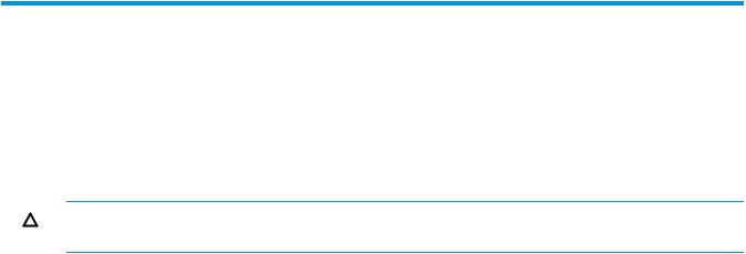
•The HP M6710 Drive Enclosure (2U24) holds up to 24, 2.5 inch small form factor (SFF) Serial Attached SCSI (SAS) disk drives, arranged vertically in a single row at the front of the enclosure (numbered 0 to 23). The back of the enclosure contains two 580 W power cooling modules (PCMs) and two I/O modules. Figure 1 (page 9) shows the 2U24 drive enclosure, and also applies to the StoreServ 7200 and 7400.
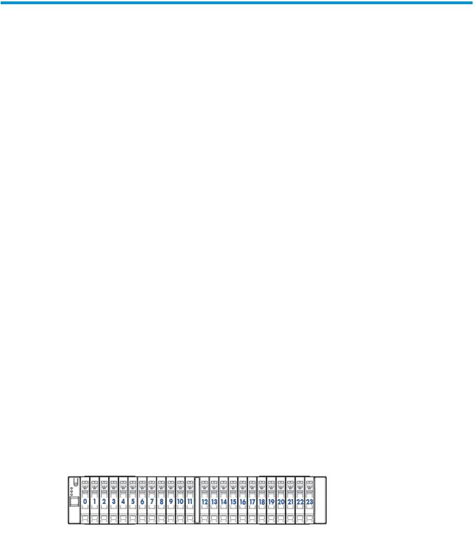
•The HP M6720 Drive Enclosure (4U24) holds up to 24, 3.5 inch large form factor (LFF) SAS disk drives, arranged horizontally with four columns of six disk drives at the front of the enclosure (numbered 0 to 23). The back of the enclosure contains two 580 W PCMs and two I/O modules. Figure 2 (page 10) shows and applies only to the 4U24 drive enclosure.
•The HP 3PAR StoreServ 7200 and 7400 controller enclosures hold up to 24, 2.5 inch SFF SAS disk drives arranged, vertically in a single row at the front of the enclosure (numbered 0 to 23). The back of the enclosure contains two 764 W PCMs and two controller nodes.
Disk Drive Numbering
There are two types of drive enclosures. The maximum number of supported drive enclosures varies based on the model and the number of nodes.
Disk drives are mounted on a drive carrier or magazine and are located the front of the enclosures.
•2.5-inch SFF disk drive numbering
Figure 1 HP M6710 Drive Enclosure (2U24) 2.5-inch SFF
•3.5-inch LFF disk drive numbering
Understanding Component Numbering |
9 |
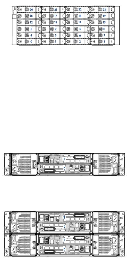
Figure 2 HP M6720 Drive Enclosure (4U24) 3.5-inch LFF
In the HP 3PAR Management Console or CLI, the enclosures are displayed as follows: DCS2 for the 2U24 (M6710), DCS1 for the 4U24 enclosure (M6720), and DCN1 for the 7200 or 7400 controller node enclosure.
Controller Nodes
The controller node is a storage system component that caches and manages data in a system and provides hosts with a coherent, virtualized view of the system. Controller nodes are located in the rear of the node enclosure.
The HP 3PAR StoreServ 7200 Storage system contains two nodes: node 0 and node 1. The HP 3PAR StoreServ 7400 Storage system can contain two nodes or four nodes: node 0 and node 1 in the lower controller enclosure, and node 2 and node 3 in the upper controller enclosure in a system with four nodes.
Figure 3 HP 3PAR StoreServ 7200 Controller Nodes
Figure 4 HP 3PAR StoreServ 7400 Controller Nodes
10 Identifying Storage System Components
Controller Node PCIe Slots and Ports
Table 1 (page 11) describes default configurations for the HP 3PAR StoreServ 7000 Storage system:
Table 1 Storage System Expansion Cards
Expansion cards |
Nodes 0 and 1 |
Nodes 2 and 3 |
||
2 |
FC HBAs only |
1 |
FC HBA each |
No expansion card |
2 |
10 Gb/s converged network |
1 |
10 Gb/s CNA each |
No expansion card |
adapter (CNA) only |
|
|
|
|
2 |
FC HBAs + 2 10 Gb/s CNAs |
1 |
FC HBA each |
1 10 Gb/s CNA each |
NOTE: If you are upgrading from a two-node to a four-node configuration, you can have CNAs installed in node 0 and node 1, and FC HBAs installed in node 2 and node 3.
Figure 5 (page 11) shows the ports on a controller node.
Figure 5 Location of Controller Node Ports
Table 2 Controller Node Ports
Item |
Port |
1 |
2 Ethernet |
|
MGMT--Used to connect to the storage array management interfaces |
|
RC--Used to connect to Remote Copy |
2 |
Fibre Channel (FC-1 and FC-2)--used to connect to host systems |
3 |
SAS (DP-2 and DP-1)--used with SAS cables to connect to the drive enclosures |
|
and I/O modules |
4 |
Node Interconnect--Used with 4 directional interconnect cables that connect |
|
the controller nodes (4-node 7400 only) |
5 |
PCI-e slot for optional 4-port 8 Gb/s FC HBA or 2-port 10 Gb/s CNA |
NOTE: |
The MFG port is not used. |
Understanding Component Numbering |
11 |
I/O Modules
The I/O modules connect the controller nodes to the hard drives using a SAS cable, enabling the transfer of data between the nodes, hard drives, PCMs, and enclosures. The I/O modules are located at the rear of the drive enclosure. There are two I/O modules per enclosure, numbered 0 and 1 from bottom to top (see Figure 6 (page 12) and Figure 7 (page 12)).
Figure 6 M6710 I/O Module
Figure 7 M6720 I/O Module
NOTE: The I/O modules are located in slots 0 and 1 of the HP M6710 and HP M6720 Drive Enclosure.
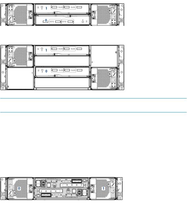
Power Cooling Modules
The power cooling module (PCM) is an integrated power supply, battery, and cooling fan. There are two types of PCMs:
•The 580 W is used in the drive enclosures and does not include a battery.
•The 764 W is used in the node enclosures and includes a replaceable battery.
The PCMs are located at the rear of the storage system, and on the sides of the enclosure. There are two PCMs per enclosure. The PCMs are numbered 0 and 1 from left to right.
Figure 8 PCM Numbering for HP 3PAR 7200 (2U) Controller Node Enclosure
12 Identifying Storage System Components
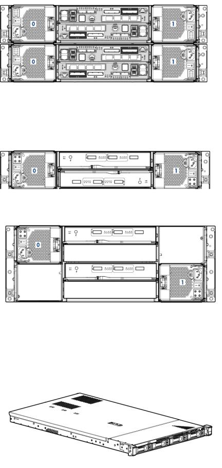
Figure 9 PCM Numbering for HP 3PAR 7400 (4U) Controller Node Enclosure
In the HP 3PAR M6720 Drive Enclosure, the two PCMs are located diagonally from one another. The remaining PCM slots are filled with blank panels (see Figure 10 (page 13) and Figure 11 (page 13)).
Figure 10 PCM Numbering for HP M6710
Figure 11 PCM Numbering for HP M6720
Service Processor
The HP 3PAR StoreServ 7000 Storage system can include an HP 3PAR Service Processor (SP) or a Virtual Service Processor (VSP). If your configuration includes an SP, it is located at the bottom of the rack under the enclosures and above the PDUs.
Figure 12 HP 3PAR Service Processor DL 320e
Understanding Component Numbering 13

For more information, see “Connecting to a Physical Service Processor” (page 48).
Power Distribution Units
In each HP G3 rack, two PDUs are mounted horizontally at the bottom of the rack, numbered 0–1 from bottom to top. The default configuration for the HP Intelligent Series Racks is two PDUs mounted vertically at the bottom of the rack so to provide a front-mounting unit space.
Make sure there is enough clearance for service. For example, the PDUs mounted vertically at the back of a rack must have enough clearance to remove node and drive chassis power supples.
NOTE: Depending on the configuration, PDUs can be mounted vertically.
14 Identifying Storage System Components

3 Setting Up a Factory-Integrated Storage System
This chapter describes the procedures for setting up a storage system that is delivered in a factory-integrated HP cabinet with all of the components installed. Before you set up a storage system, ensure all requirements documented in the HP 3PAR StoreServ 7000 Storage Site Planning Manual have been met.
WARNING! Do not use this procedure if you are installing storage system components into an existing or partially populated rack. To install storage system components into an existing rack, see “Installing Storage System Components into a Rack” (page 19).
Unpacking the Cabinet
When unpacking the rack, refer to the unpacking diagrams on the outside of the cardboard shipping container.
CAUTION: To avoid tipping the cabinet, one person must guide the cabinet down the ramp, with the other person pushing from behind.
To unpack the rack:
1.Locate the front of the shipping container and unlatch the four rotary latches securing the front panel. To unlatch the rotary latches, raise the levers and turn them counterclockwise one half-turn.
2.Lower the front panel of the shipping container to form a ramp.
3.Remove the packing foam from the front of the storage system.
4.Remove the rack from the container.
5.Carefully guide the rack down the ramp.
6.Remove the plastic packing materials and place them into the shipping container for reuse.
Positioning the Cabinet
CAUTION: To prevent potential damage to system equipment, do not adjust the position of the cabinet when the power is on.
Position the cabinet in the operating location. If the operating location has raised floor tiles with cutouts to facilitate cable routing, position the cabinet over the cutouts in the tiles. See the HP 3PAR StoreServ 7000 Storage Site Planning Manual for more information on the structural considerations for using raised flooring.
After positioning the storage system, use the four leveling feet to stabilize the cabinet and prevent movement during operation:
1.Using an adjustable wrench, turn each leveling foot clockwise until the weight of the rack rests on the leveling feet instead of the casters.
2.Using the wrench, lock the leveling feet in place by turning the locking nut on each foot counterclockwise until tight.
3.Verify the rack is stationary.
For more information on final positioning, see “Repositioning the Storage System” (page 37).
Verify the Cabling
The cabling for a factory-integrated storage system is complete. You must plug in the power cords and install the host and Ethernet cables.
Unpacking the Cabinet |
15 |
NOTE: In a four-node 7400 system, two cable management brackets have Velcro straps to hold the cables. You can remove and discard these brackets, but HP recommends saving them for future use. To remove the cable management brackets, loosen the Torx screws and unlatch the Velcro straps to free the cabling.
Installing and Removing the Cable Restraint Shipping Brackets
The cable restraint shipping brackets support the connected data cables and connectors during transport. HP recommends installing the brackets before transporting the system to another location to prevent damage to the connectors. The brackets are not required if the system is in a stationary position. Retain and store the brackets if they are not being used.
Installing the Brackets
1.Connect the data cables to the enclosure.
2.Attach the hook and loop straps to the brackets.
3.Align the brackets so they parallel to the edges of the enclosure link connectors (see
Figure 13 (page 16)). Adjust the brackets to the height of the screw holes located on the side rails.
Figure 13 Aligning the Brackets
16 Setting Up a Factory-Integrated Storage System
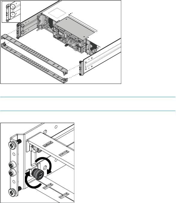
4.Attach the brackets to the side rails.
Figure 14 Attaching the Brackets to the Side Rails
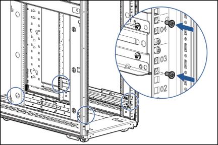
5.Tighten the captive screws (see Figure 15 (page 17)).
NOTE: Make sure the brackets are aligned and leveled with the link connectors before tightening the captive screws. HP recommends tightening the screws to 19 in-lbs.
Figure 15 Tightening the Captive Screws
Installing and Removing the Cable Restraint Shipping Brackets |
17 |
Removing the Brackets
Remove the cable restraint shipping brackets only when the cabinet is in its final location.
Procedure 1
1.Remove the data cables from the hook and loop straps.
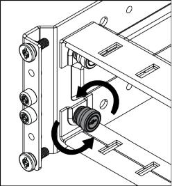
2.Loosen the captive screws (see Figure 16 (page 18)).
Figure 16 Loosening the Captive Screws
3.Remove the brackets. Be careful not to damage the attached data cables.
Now continue on to“Verifying Setup and Powering On the Storage System” (page 37) and verify setup before powering on the storage system and initializing the SP and storage system software.
18 Setting Up a Factory-Integrated Storage System

4 Installing Storage System Components into a Rack
This chapter describes the procedures for installing storage system components in an existing rack. Before you set up a storage system, ensure that all requirements documented in the HP 3PAR StoreServ 7000 Storage Site Planning Manual have been met.
Follow these procedures if you are installing any of the following storage system components in an existing or partially populated rack:
•PCIe adapters
•Disk Drive enclosures
•Controller node enclosures
•Cables
•Disk drives
To set up a storage system delivered in a fully loaded HP cabinet, see “Setting Up a Factory-Integrated Storage System” (page 15).
Unpacking Disk Drive and Controller Node Enclosures
The enclosure includes nodes, I/O modules, and PCMs.
CAUTION: The enclosure is heavy. Lifting, moving, or installing it requires two people.
To unpack the enclosure:
1.Cut open the cardboard box and remove the top.
2.Remove the rail kit.
3.Remove the packing foam around the enclosure.
4.Remove the enclosure from the box.
Installing the Rail Kit
Before you install the enclosure in the rack, you must mount the two rail shelves to the rack.
To mount a one unit (1U) rail shelf (used for installing a SP) to the rack, follow the installation instructions included with the rail kit.
Table 3 (page 19) lists the rail kit part numbers for each type of installation.
Table 3 Part Numbers
2U Enclosure |
4U Enclosure |
Rail Kit Assembly 692981-001 |
Rail Kit Assembly 692982-001 |
NOTE: For more information about the rail kit assembly, see “Rail Kits” (page 83).
The rail kit contains two rails, two middle support brackets, and T-25 Torx screws. The rail channels are mounted to the inside of the rack using two shoulder screws at each end of the rack (four screws per rail), and a middle support bracket for mounting between the adjustable rails. Installing the middle support bracket applies only to the 2U and 4U enclosures. The following text is imprinted on both ends of the rails: FRONT-R and FRONT-L.
NOTE: The middle support bracket is only used in an HP rack with posts that extend to a depth of 29-inches. Install the middle support bracket when transporting the system to another location. Retain and store the middle support brackets if they are not being used.
Unpacking Disk Drive and Controller Node Enclosures 19
Mounting a 2U rail shelf onto the rack
1.Determine the location of the directional-specific rail matches with the side of a rack post. The following text is imprinted on both ends of the rails: FRONT-R and FRONT-L.
2.Align one end of the rail channel with the holes of the rack post, and then push to seat the locating pins in the rack.
3.Expand the rail to connect to the other end of rack post.
4.Secure the front and rear of the rail assembly to the rack post using four T25 Torx shoulder screws (two in front, two in back) in the top and bottom holes. Tighten the shoulder screws with a torque of 19 in-lbs.
Figure 17 Mounting the 2U Rail Shelf
5.Repeat steps 1 through 4 for the other rail.
6.Check both sides at the front and back of the rack to ensure all screws are installed properly.
Mounting a 4U rail shelf onto the rack
1.Verify each directional-specific rail matches with the side of a rack post.
The following text is imprinted on both ends of the rails: FRONT-R and FRONT-L.
2.Align one end of the rail channel with the holes of the rack post, and then push to seat the locating pins in the rack.
3.Expand the rail to connect to the other end of rack post.
4.Secure the front and rear of the rail assembly to the rack post using four T25 Torx shoulder screws (two in front, two in back) in the top and bottom holes. Tighten the shoulder screws with a torque of 19 in-lbs.
20 Installing Storage System Components into a Rack
5.Install the middle support bracket before transporting:
a.Align the middle support bracket holes with the top holes of the rail(s). The orientation of the middle support bracket is neutral.
b.Insert and tighten screws.
Figure 18 Installing the Middle Support Bracket
6.Repeat steps 1 through 5 for the other rail.
7.Snap one cage nut into the rack hole two positions above the rail on both sides.
Figure 19 Installing the Cage Nut
8.Check both sides at the front and back of the rack to ensure all screws are installed properly.
Installing the Rail Kit |
21 |

Installing PCIe Adapters in the Controller Nodes
PCIe adapters connect the controller nodes to host computers and disk drives. Installing or upgrading PCle adapters involves adding additional supported types of adapters or replacing existing adapters.
WARNING! Fibre Channel HBA and iSCSI CNA upgrades on the HP 3PAR StoreServ 7400 Storage system must be serviced by authorized service personnel and cannot be done by a customer. Contact your local service provider for assistance. Upgrades on the HP 3PAR StoreServ 7200 Storage systems may be performed by the customer.
CAUTION: To avoid possible data loss, only one node at a time should be removed from the storage system. To prevent overheating, node replacement requires a maximum service time of 30 minutes.
NOTE: When installing the first two HBAs or CNAs in a controller node, install the HBAs in node 0 and node 1. If two FC HBAs and two CNA HBAs are added to a controller node, install the FC HBAs in node 0 and node 1, and then install the CNA HBAs in node 2 and node 3.
1.Remove the controller node and then the cover.
2.If a PCIe Adapter Assembly is already installed, do the following steps:
a.Remove the PCIe Adapter Assembly, and disconnect the PCIe Adapter from the riser card.
b.Install the new PCIe Adapter onto the riser card, and insert the assembly into the node.
3.If a PCIe Adapter is not installed, do the following steps:
a.Remove the PCIe Adapter riser card.
b.Install the new PCIe Adapter onto the riser card, and insert the assembly into the node.
4.Replace the node cover and the node.
Installing Enclosures
The storage system can contain the following types of drive and controller node enclosures: 2U and 4U enclosures.
WARNING! The enclosure is heavy. Lifting, moving, or installing the enclosure requires two people.
NOTE: When installing a 7400 (two-node) enclosure, two units of space must be reserved above the enclosure for an upgrade to a four-node system. Labels are provided to secure on two filler panels to reserve this space.
To install an enclosure on the rack:
22 Installing Storage System Components into a Rack
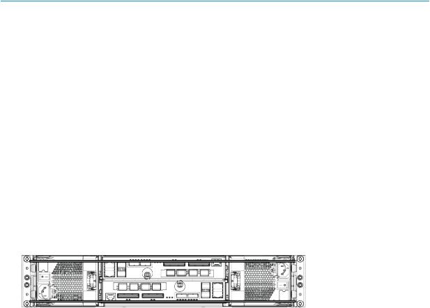
1.Determine that the enclosure is oriented correctly by looking at the rear of the enclosure. Verify the node numbering by reviewing the controller node label on both edges of the enclosure slot.
Figure 20 Verify Controller Node Numbering
2.At the front of the enclosure, remove the yellow bezels on each side of the enclosure to expose the mounting holes.
3.Slide the enclosure onto the rail shelves. Use both hands to handle the enclosure.
4.At the front of the enclosure, do one of the following steps:
•For 2U enclosures, insert one Torx M5 (long) screw into the mounting hole on each side to secure the enclosure to the rack. Tighten the screws to a torque level of 13 in-lbs.
•For 4U enclosures, insert two Torx M5 (long) screws into the mounting holes on each side to secure the enclosure to the rack (on each side, one screw goes into the rail and the other to the cage nut). Tighten the screws to a torque level of 13 in-lbs.
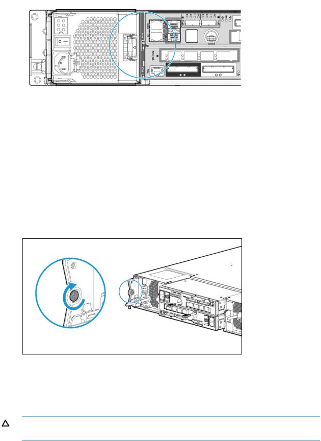
5.At the rear of the enclosure, tighten the two M5 Torx (short) screws on the sides of the enclosure. Tighten the screws to a torque level of 13 in-lbs. See Figure 21 (page 23).
Figure 21 Tightening the Hold-Down Screw
NOTE: Due to limited access, use a short length or right angle torx bit screwdriver to tighten the hold-down screws.
6.Reinsert the yellow bezels on each side of the enclosure.
7.Connect power and data cables.
CAUTION: Do not power on without completing the remainder of the physical installation or upgrade.
Installing Enclosures |
23 |
8.Remove the blank filler panels before Installing disk drives into the slots.
9.To ensure proper thermal control, install blank filler panels into any empty slots.
Guidelines for Installing Disk Drives in Disk Enclosures
This section provides information about the requirements and installation order for disk drives in SFF and LFF drive enclosures.
Only 2.5 inch drives can be installed in HP M6710 (2U) and M6720 (4U) controller node and drive enclosures. The 3.5 inch drives can be installed only in 4U M6720 drive enclosures.
For all drive enclosures, the slots should be balanced. For example, if two drives are added to DP-1, two drives should be added to a drive enclosure attached to DP-2. Drives should be added so that all enclosures are balanced with an even number of drives in each enclosure.
For all drive enclosures, the proper system temperature must be maintained. To ensure proper thermal control, blank filler panels must be installed in any slots without drives.
Guidelines for Allocating and Loading Order (2.5 inch SFF disk drive)
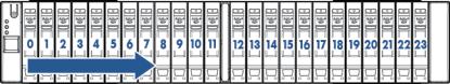
For a node or M6710 Drive Enclosure, drives must be added in identical pairs, starting from slot 0 on the left and filling to the right, leaving no empty slots between drives. The best practice when upgrading or building a system is to add the same number of identical drives to every drive enclosure in the system, with a minimum of three disk drive pairs in each drive enclosure.
Figure 22 HP M6710 Drive Enclosure (2U24) Disk Drive Placement Order
Guidelines for Allocating and Loading Order (3.5 inch Large Form Factor (LFF) disk drive)
Columns of drives in an HP M6720 Drive Enclosure must be of the same device type (NL or SSD). NL disk drives and SSDs must not be mixed in the same column. For an HP M6720 Drive Enclosure, drives must be installed in identical pairs, starting from the slot at the bottom of the left column and filling up with drives of the same type, leaving no empty slots between drives in the column. Populate drives in the columns from bottom to top and from left to right.
The best practice when upgrading or building a system is to add the same number of identical drives to every HP M6720 Drive Enclosure in the system, with a minimum of two drives added to each LFF chassis. The minimum supported upgrade for a 7400 with one or more expansion HP M6720 Drive Enclosures is two identical drives added to adjacent slots in the same column of the same chassis. If there are more than one expansion enclosure in the system, add the drives in pairs so they are balanced across the device ports, and then added to enclosures on the same port.
The LFF drives added to the HP M6720 Drive Enclosure on each node pair should be balanced across node pairs, then across device ports on each node pair, and finally by enclosures on the same port.
24 Installing Storage System Components into a Rack
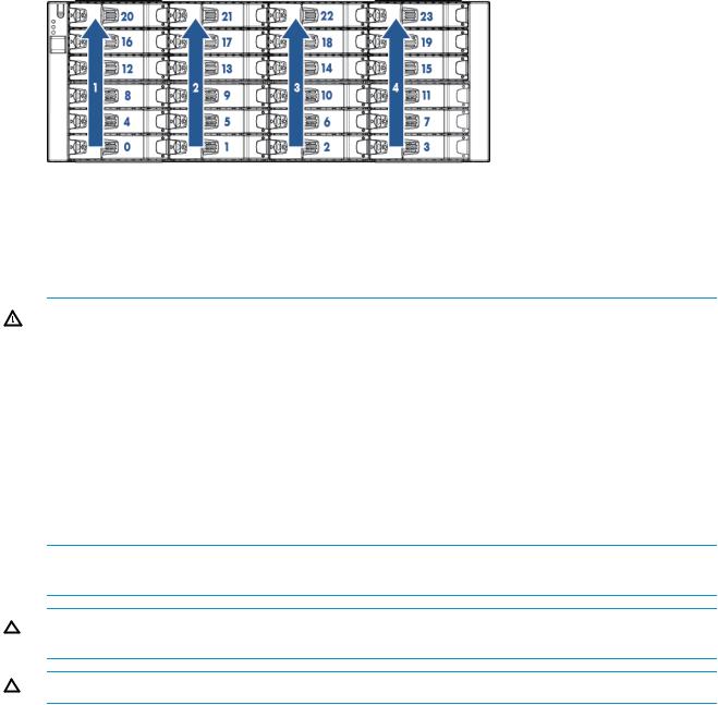
Figure 23 M6720 Drive Enclosure (4U24) Disk Drive Placement Order
Guidelines for Allocating and Loading Order (Mixed SFF and LFF disk drives)
In a storage system with mixed HP M6710 and M6720 Drive Enclosures there is a minimum of three pairs of drives for each drive enclosure. Additional upgrades can include all SFF, LFF or a mixture of SFF and LFF drives but, they must be in pairs of the same drive type. Follow the loading order as in the sections above for SFF and LFF drives.
WARNING! If the StoreServ is enabled with the Data-at-Rest (DAR) encryption feature, only use the self-encrypting drives (SED). Using a non-self-encrypting drive may cause errors during the upgrade process.
For information about encrypting the hard drives with an enhanced security feature known as Data-At-Rest (DAR) encryption, see “Enhancing Security with Data Encryption” (page 86).
For information about adding drive enclosures, see “Adding Disk Drives and Expansion Drive Enclosures” (page 87).
Installing a Disk Drive
Before beginning this procedure, review how to load the drives based on drive type, speed, and capacity. See “Guidelines for Installing Disk Drives in Disk Enclosures” (page 24).
NOTE: To avoid any cabling errors, all drive enclosures must have at least one or more hard drives installed before powering on the enclosure.
CAUTION: Blank disk drive filler panels are provided and must be used if all slots in the enclosure are not filled with disk drives.
CAUTION: To avoid potential damage to equipment and loss of data, handle disk drives carefully.
Each disk drive includes a green and amber LED on the front to indicate disk drive status.
Installing a 2.5 inch Disk Drive (SFF)
1.Press the handle latch to open the handle.
2.Insert the disk drive into the enclosure with the handle opened from the top in the vertical position.
3.Slide the disk drive into the enclosure until it engages. Push firmly until it clicks.
Guidelines for Installing Disk Drives in Disk Enclosures |
25 |

Figure 24 Installing a 2.5 inch Disk Drive
Installing a 3.5 inch Disk Drive (LFF)
1.Press the handle latch to open the handle.
2.Position the disk drive so the handle opens from the left, and slide it into the enclosure.
3.Push firmly until the handle fully engages and clicks.
Figure 25 Installing a 3.5 inch disk drive
26 Installing Storage System Components into a Rack
Installing the Service Processor in the Storage System
The HP 3PAR Service Processor consists of the following:
•A standard HP Server
•A 1U Rail Kit for that specific server
NOTE: The SP ID is the HP 7-digit serial number of the array located on the top front of the server and in a pull-out placard in the front of the server. The serial number is preceded by SP000. For example, if the 3PAR serial number is 1614983, enter SP0001614983.
Use these procedures when installing an HP 3PAR Service Processor in an existing rack. Before you begin, verify that you have the proper service processor 1U Mounting Kit (PN 683811-001).
The service processor rail kit supports a variety of products in round, square, or threaded-hole racks. The following table identifies any tools required for each type of rack.
Table 4 Rack Types
Rack Type |
Tools Required |
Picture |
Round hole |
None |
|
Square hole |
None |
|
Threaded hole |
Screwdriver |
|
The following components are included in the kit:
•Slide mounting rails
•Screws
•Cage nuts (for the round-hole rack)
•Cable management straps
•Labels
Installing the Service Processor in the Storage System |
27 |
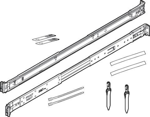
Figure 26 Rail Kit Components
In addition to the supplied items, you may also need the following:
•Screws fitting a threaded-hole rack
•Screwdriver
•Optional cable management arm (see Figure 27 (page 29))
28 Installing Storage System Components into a Rack
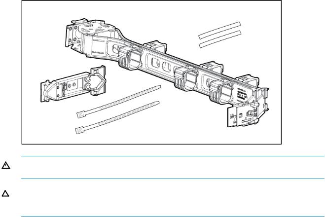
Figure 27 Cable Management Arm
WARNING! To avoid risk of injury or damage to the equipment, do not stack anything on top of rail-mounted equipment or use it as a work surface when it is extended from the rack.
CAUTION: Always plan the rack layout before installing the equipment. See HP 3PAR StoreServ 7000/7450 Cabling Configuration Guide for the best practices for node and drive enclosure positioning in specific configurations.
To install the rail kit and service processor:
1.Adjust the length of the mounting rails.
2.Install the threaded-hole cage nuts and rail mounting pins into the rack hole positions where you want to install the component. Use two cage nuts and two rail mounting pins on the front of each rail, and two cage nuts and two rail mounting pins on the rear of each rail.
Installing the Service Processor in the Storage System |
29 |
Loading...