


Service Manual
HP OmniBook 800CS/CT
Thank you for purchasing this Factory Service Manual CD/DVD from servicemanuals4u.com.
Please check out our eBay auctions for more great deals on Factory Service Manuals:
servicemanuals4u

Notice
In a continuing effort to improve the quality of our products, technical and environmental information in this document is subject to change without notice.
Hewlett-Packard makes no warranty of any kind with regard to this material, including, but not limited to, the implied warranties of merchantability and fitness for a particular purpose. HewlettPackard shall not be liable for errors contained herein or for incidental or consequential damages in connection with the furnishing, performance, or use of this material.
Hewlett-Packard assumes no responsibility for the use or reliability of its software on equipment that is not furnished by Hewlett-Packard.
As an ENERGY STAR partner, HP has determined that these products meet the ENERGY STAR guidelines for energy efficiency.
All Certifications may not be completed at product introduction. Please check with your HP reseller for certification status.
This equipment is subject to FCC rules. It will comply with the appropriate FCC rules before final delivery to the buyer.
ENERGY STAR is a service mark of the U.S. Environmental Protection Agency. IBM and OS/2 are registered trademarks and TrackPoint is a trademark of International Business Machines Corporation. Pentium and the Intel Inside logo are registered trademarks and MMX is a trademark of Intel Corporation. Photo CD is a registered trademark of Kodak Corporation. Microsoft, MS-DOS, and Windows are registered trademarks, and the Genuine Microsoft Products logo is a trademark of Microsoft Corporation in the United States of America and in other countries. Sound Blaster is a trademark of Creative Technology Ltd.
© Hewlett-Packard Company 1997.
All Rights Reserved. Reproduction, adaptation, or translation without prior written permission is prohibited except as allowed under copyright laws.
Printed in U.S.A.
F1360-90049

Table of Contents |
|
List of Figures............................................................................................................................. |
iii |
List of Tables.............................................................................................................................. |
iv |
Introduction ................................................................................................................................. |
v |
Product Overview........................................................................................................................ |
1 |
What’s New ............................................................................................................................. |
2 |
Product Features ..................................................................................................................... |
3 |
Product at a Glance ................................................................................................................. |
4 |
Product Comparisons............................................................................................................... |
6 |
Troubleshooting........................................................................................................................... |
3 |
Power-On Self-Test ................................................................................................................. |
4 |
Beep Codes.......................................................................................................................... |
4 |
Display Codes ...................................................................................................................... |
5 |
OmniBook Diagnostics............................................................................................................. |
7 |
Running the diagnostics program.......................................................................................... |
7 |
Main diagnostic screen ......................................................................................................... |
7 |
Special test hardware requirements...................................................................................... |
9 |
Loop Back Connectors........................................................................................................ |
10 |
Command line options........................................................................................................ |
12 |
User interface commands................................................................................................... |
13 |
Details on using the diagnostic tests ................................................................................... |
17 |
Desktop Management Interface (DMI).................................................................................... |
28 |
Description of DMI.............................................................................................................. |
28 |
Contents of the DMI Package ............................................................................................. |
28 |
Setup and Configuration ........................................................................................................ |
31 |
SCU Main Screen............................................................................................................... |
31 |
System Menu Screen ......................................................................................................... |
32 |
Password Configuration...................................................................................................... |
34 |
Input/Output Menu Screen.................................................................................................. |
35 |
Power Menu Screen ........................................................................................................... |
37 |
Default Menu Screen.......................................................................................................... |
38 |
Exit Menu Screen ............................................................................................................... |
39 |
Troubleshooting Tips.............................................................................................................. |
40 |
OmniBook Components...................................................................................................... |
40 |
CD ROM Drive Troubleshooting ......................................................................................... |
45 |
Resolving Docking Station Operating Problems.................................................................. |
46 |
Resolving OmniBook Docking Problems ............................................................................ |
47 |
Hardware Repair ....................................................................................................................... |
49 |
Battery (End User Replaceable)............................................................................................. |
50 |
Memory (End User Replaceable) ........................................................................................... |
51 |
Hard Disk Drive (End User Replaceable) .............................................................................. |
53 |
Hard Disk Drive Breather Holes.......................................................................................... |
57 |
Mouse (End User Replaceable).............................................................................................. |
58 |
Small Parts (End User Replaceable) ...................................................................................... |
59 |
Battery Latch ...................................................................................................................... |
59 |
I/O Door ............................................................................................................................. |
59 |
Memory Cover.................................................................................................................... |
59 |
PCMCIA Card Tray............................................................................................................. |
59 |
Rubber Feet ....................................................................................................................... |
59 |
Keyboard (HP Authorized Service Providers Only) ................................................................ |
60 |
Display (HP Authorized Service Providers Only).................................................................... |
62 |
CPU (HP Authorized Service Providers Only) ........................................................................ |
67 |
Heat Transfer Disk.............................................................................................................. |
68 |
Logic PCA Board (HP Authorized Service Providers Only)..................................................... |
70 |
i

Electronic Serial Number.................................................................................................... |
70 |
Paw Active (HP Authorized Service Providers Only).............................................................. |
73 |
Other Components and Accessories (HP Authorized Service Providers Only)........................ |
74 |
Appendix A - Technical Specifications....................................................................................... |
78 |
Mass Storage Specifications .................................................................................................. |
78 |
Hard Disk Drive .................................................................................................................. |
78 |
Floppy Disk Drive ............................................................................................................... |
78 |
CD-ROM Drive ................................................................................................................... |
79 |
System Resources ................................................................................................................. |
80 |
System Interrupts (IRQs) .................................................................................................... |
80 |
DMA Channels ................................................................................................................... |
81 |
Memory Map ...................................................................................................................... |
81 |
I/O Addresses..................................................................................................................... |
82 |
Appendix B - Hewlett-Packard Password Removal Policy.......................................................... |
83 |
Appendix C - Hewlett-Packard TFT Display Quality Statement.................................................. |
85 |
Appendix D - OmniBook Diagnostics BIOS Checksums ............................................................ |
86 |
Appendix E - OmniBook Diagnostics Error Messages................................................................ |
87 |
Hewlett-Packard supplied test messages ............................................................................ |
87 |
Watergate Software supplied test messages ...................................................................... |
90 |
Appendix F - Part Numbers ....................................................................................................... |
95 |
ii

List of Figures |
|
Figure 1 - OmniBook 800 External Features................................................................................ |
3 |
Figure 2 - OmniBook 800 External Features (continued) ............................................................. |
3 |
Figure 3 - Exploded Diagram....................................................................................................... |
4 |
Figure 4 - Main Diagnostic Screen............................................................................................... |
8 |
Figure 5 - Serial Loop Back Connector ...................................................................................... |
10 |
Figure 6 - Parallel Loop Back Connector ................................................................................... |
10 |
Figure 7 - SCSI Loop Back Connector ....................................................................................... |
10 |
Figure 8 - SyCard Solder Bridges .............................................................................................. |
11 |
Figure 9 - Sycard Test Results .................................................................................................. |
19 |
Figure 10 - Keyboard Test Screen ............................................................................................. |
21 |
Figure 11 - Mouse Test Screen (text mode)............................................................................... |
23 |
Figure 12 - Mouse Test Screen (graphics mode) ....................................................................... |
24 |
Figure 13 - Dock Keyboard Test Screen .................................................................................... |
27 |
Figure 14 - DMI Components..................................................................................................... |
29 |
Figure 15 - Removing the Battery.............................................................................................. |
50 |
Figure 16 - 8- and 16-MB Memory Modules............................................................................... |
51 |
Figure 17 - New and Old 32-MB Memory Module (respectively) ................................................ |
51 |
Figure 18 - Removing the Memory Module................................................................................ |
52 |
Figure 19 - Hard Drive Screws................................................................................................... |
53 |
Figure 20 - Folding the Keyboard Open ..................................................................................... |
54 |
Figure 21 - Hard Drive Removal................................................................................................ |
54 |
Figure 22 - Hard Drive Removal (continued) ............................................................................. |
55 |
Figure 23 - Hard Drive Insulator Flap......................................................................................... |
55 |
Figure 24 - Inserting the Hard Drive........................................................................................... |
56 |
Figure 25 - Proper Keyboard Flex Cable Position ...................................................................... |
56 |
Figure 26 - IBM and Toshiba Hard Drive Breather Holes (respectively) ..................................... |
57 |
Figure 27 - Removing the Mouse............................................................................................... |
58 |
Figure 28 - Keyboard Screws..................................................................................................... |
60 |
Figure 29 - Folding the Keyboard Open ..................................................................................... |
60 |
Figure 30 - Keyboard Flex Cables ............................................................................................. |
61 |
Figure 31 - Keyboard Flex Cable Placement ............................................................................. |
61 |
Figure 32 - Bottom Case Screws and Rubber Feet .................................................................... |
62 |
Figure 33 - Keyboard Support Plate Screws .............................................................................. |
63 |
Figure 34 - Display Flex Cables................................................................................................. |
64 |
Figure 35 - Top Case and Display Removal .............................................................................. |
65 |
Figure 36 - Intel Inside Sticker Placement ................................................................................. |
66 |
Figure 37 - Removing the CPU.................................................................................................. |
67 |
Figure 38 - Heat Transfer Disk and Keyboard Support Insulator ................................................ |
68 |
Figure 39 - CPU Thermal Coupling............................................................................................ |
68 |
Figure 40 - Logic PCA Removal ................................................................................................ |
71 |
Figure 41 - Grommet and Bushing Placement ........................................................................... |
72 |
Figure 42 - Paw Active Removal ............................................................................................... |
73 |
iii

List of Tables |
|
Table 1 - Parts Identification........................................................................................................ |
5 |
Table 2 - POST Beep Codes ....................................................................................................... |
4 |
Table 3 - POST Display Codes.................................................................................................... |
5 |
Table 4 - Diagnotic Command Line Options .............................................................................. |
12 |
Table 5 - Diagnostic Test Selection Commands ........................................................................ |
13 |
Table 6 - Diagnostic Commands for Toggling Settings .............................................................. |
14 |
Table 7 - Diagnostic Hidden Commands.................................................................................... |
15 |
Table 8 - Diagnostic Test Parameters........................................................................................ |
16 |
Table 9 - System Menu Settings................................................................................................ |
32 |
Table 10 - System Password Matrix .......................................................................................... |
34 |
Table 11 - Input/Output Menu Settings ...................................................................................... |
35 |
Table 12 - Power Menu Settings................................................................................................ |
37 |
Table 13 - Default Menu Settings .............................................................................................. |
38 |
Table 14 - Exit Menu Settings.................................................................................................... |
39 |
Table 15 - OmniBook Troubleshooting Tips............................................................................... |
40 |
Table 16 - CD-ROM Troubleshooting Tips ................................................................................. |
45 |
Table 17 - Hard Disk Drive Specifications.................................................................................. |
78 |
Table 18 - Floppy Disk Drive Specifications............................................................................... |
79 |
Table 19 - CD-ROM Drive Specifications .................................................................................. |
79 |
Table 20 - Interrupts for F1171 - F1175 ..................................................................................... |
80 |
Table 21 - Interrupts for F1360 .................................................................................................. |
80 |
Table 22 - DMA Channels for F1171 - F1175, and F1360.......................................................... |
81 |
Table 23 - Memory Map for F1171 - F1175 ............................................................................... |
81 |
Table 24 - Memory Map for F1360 ............................................................................................ |
81 |
Table 25 - I/O Address for F1171 - F1175 ................................................................................. |
82 |
Table 26 - I/O Addresses for F1360........................................................................................... |
82 |
Table 27 - OmniBook F1171 - F1175 BIOS Checksums ............................................................ |
86 |
Table 28 - OmniBook F1360 BIOS Checksums ......................................................................... |
86 |
iv

Introduction
This document provides reference information for the HP OmniBook 800. It is intended to be used by HP-qualified service personnel to help with the installation, servicing, and repair of these HP OmniBook PCs.
It is a self-paced guide designed to train you to install, configure, and repair the OmniBook Notebook PC. You can follow it without having any equipment available.
The following table lists additional sources where supplementary information can be obtained:
Resource |
Number/Address |
Comments |
HP External Web |
http://hpcc998.external.hp.com/mcd/ |
No usage restriction |
HP-MCD Internal Web |
http://webmcd.cv.hp.com |
Restricted to HP internet |
|
|
access only |
HP MCD Service |
svc-eng_mcd@om.cv.hp.com |
Email address for service |
Engineer |
|
related questions and |
|
|
issues |
v

Part 1
Product Overview
∙What’s New
∙Product Features
∙Product at a Glance
∙Product Comparisons
What’s New
This version of the HP OmniBook 800 Service Manual has been updated to include the HP OmniBook 800 with MMXä Technology (F1360A). The following is a list comparing the technologies of the various models of the OmniBook 800.
Feature |
OmniBook 800 with MMX |
OmniBook 800 |
|
(F1360) |
(F1171 - F1175) |
Processor |
Intel Pentiumâ 166-MHz with |
Intel Pentium 100and 133- |
|
MMX Technology |
MHz processor |
Cache |
512-KB L2 |
256-KB L2 |
Video |
NeoMagic NM2093 128-bit |
NeoMagic NM2070 128-bit |
|
accelerated controller with |
accelerated controller with |
|
2MB video RAM and Zoom |
1MB RAM |
|
Video |
|
PC Card |
CardBus support |
No CardBus support |
Desktop Management |
Pre-installed DMI 1.1 software |
No DMI software installed |
Interface |
|
|
Advanced Power |
APM 1.2 |
APM 1.1 |
Management |
|
|
2
Product Features
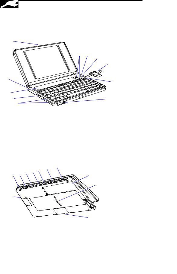
The following two illustrations point out the key external features of the OmniBook 800.
|
1 |
|
|
|
|
|
|
|
|
|
11 |
10 |
|
|
|
|
|
|
|
9 |
|
|
|
|
|
|
8 |
2 |
|
|
|
|
|
7 |
|
|
|
|
|
|
|
3 |
|
|
|
|
|
|
|
4 |
|
|
|
|
6 |
|
5 |
|
|
|
|
|
Figure 1 - OmniBook 800 External Features |
|
|||||
1. |
Latch |
|
|
|
7. |
On/Off key |
2. |
Kensington security connector |
8. |
Mouse |
|||
3. |
Fn-key icon strip |
|
|
9. |
Mouse-eject button |
|
4. |
Sound jacks |
|
|
10. Charging light |
||
5. |
Card slots |
|
|
|
11. Display adjustments |
|
6. |
Card-eject lever |
|
|
|
|
|
|
|
15 14 |
13 |
12 |
|
|
|
18 17 16 |
|
|
|
||
|
|
|
|
22 |
||
|
|
|
|
|
||
|
|
|
|
|
|
21 |
|
19 |
|
|
|
|
|
|
|
|
|
|
|
20 |
|
Figure 2 - OmniBook 800 External Features (continued) |
|||||
12. |
Docking/SCSI port |
|
|
18. AC adapter socket |
||
13. |
Parallel port connector |
|
19. Reset button |
|||
14. |
Infrared port (IrDA) |
|
|
20. Memory-expansion slot |
||
15. |
Serial port connector |
|
21. Identification pocket |
|||
16. |
Floppy drive port |
|
|
22. Battery |
||
17. |
VGA output connector |
|
|
|
||
3

Product at a Glance
The following diagram represents all models of the OmniBook 800. Use Table 1 to identify each part for the F1171 - F1175, and F1360 OmniBooks. Refer to the corresponding repair procedure(s) in Part 3 for the exact placement of each component.
|
33 |
|
32 |
33 |
6 |
|
||
34 |
|
32 |
14
|
|
|
|
|
|
|
|
|
|
|
16 |
|
|
|
|
|
37 |
40 |
|
|
|
|
1 |
|
|
|
|
|
|
|
|
|
|
|
|
|
|
|
|
|
40 |
|
28 |
|
|
21 |
|
|
4 |
|
|
|
|
|
|
|
|
|
|
|
|
|
|
40 |
25 |
|
|
|
|
|
|
|
|
|
|
|
|
|
|
|
|
||
|
|
|
|
|
|
|
|
|
|
|
|
|
|
|
|
|
|
|
|
|
|
|
12 |
39 |
39 |
|
|
|
7 |
|
|
|
|
|
|
|
38 |
|
|
|
|
|
|
|
|
||
|
|
|
|
28 |
|
|
|
|
|
|
|
|
|
|
|
|
|
|
|
|
|
|
|
|
|
|
|
|
|
|
|
|
|
|
2 |
|
|
|
|
9 |
|
30 |
|
|
|
|
2 |
|
|
|
|
|
|
|
|
|
|
15 |
|
|
|
|
|
|
18 |
|
|
|
|
|
28 |
|
|
|
|
|
|
|
|
|
|
|
|
|
|
|
|
|
|
30 |
35 |
|
|
|
30 |
17 |
|
|
|
|
|
|
|
|
|
|
|
|
|
|
|
|
|
|
|
|
|
|
|
|
|
|
|
|
|
|
30 |
|
|
30 |
23 |
|
|
|
|
|
|
|
|
|
|
35 |
|
|
|
|
|
|
26 |
|
36 |
|
|
36 |
|
|
|
|
|
|
|
36 |
|
|
22 |
||
|
|
|
|
|
|
|
|
|
|||
|
|
|
|
|
|
8 |
|
|
|
||
|
|
|
|
|
|
29 |
|
|
29 |
|
|
|
|
|
|
|
|
|
|
30 |
|
||
|
|
31 |
|
|
|
|
|
|
20 |
|
|
|
|
|
|
3 |
|
|
29 |
|
|
||
|
31 |
|
|
|
|
|
|
|
|
||
|
|
|
|
|
|
|
|
|
27 |
|
|
|
|
|
|
|
10 |
|
|
|
|
|
|
5 |
|
|
|
|
|
|
|
|
|
|
|
|
|
|
|
|
|
19 |
|
|
|
|
11 |
|
|
|
|
|
|
|
|
|
|
|
|
13 |
|
|
|
|
|
|
|
24 |
|
|
|
|
|
|
|
|
|
|
|
|
|
|
Figure 3 - Exploded Diagram
4

Table 1 - Parts Identification
|
DESCRIPTION |
PART |
EXCHANGE |
CUSTOMER |
F1171 - |
F1360 |
|
||||||
|
|
NUMBER |
PART NUMBER |
REPLACEABLE |
F1175 |
Only |
1 |
BATTERY - LI-ION |
F1121-80002 |
|
yes |
|
|
2 |
BATTERY LATCH |
F1170-40006 |
|
yes |
|
|
3 |
BUSHING |
F1170-40025 |
|
no |
|
|
4 |
CARD TRAY ASSY |
F1052-60005 |
|
yes |
|
|
5 |
CPU |
|
|
|
|
|
|
CPU 100MHZ |
F1170-60919 |
F1170-69019 |
no |
|
|
|
CPU 133MHZ |
F1170-60920 |
1170-69020 |
no |
|
|
|
CPU 166MHZ |
F1360-60911 |
1360-69011 |
no |
|
|
6 |
DISPLAY |
|
|
|
|
|
|
DISPLAY CSTN |
F1170-60902 |
F1170-69002 |
no |
|
|
|
DISPLAY TFT |
F1170-60901 |
F1170-69001 |
no |
|
|
|
DISPLAY TFT |
F1360-60901 |
F1360-69001 |
no |
|
|
7 |
DOOR - PIVOT LEFT |
F1052-40007 |
|
no |
|
|
8 |
EJECT ARM LEFT |
F1360-40005 |
|
no |
|
|
9 |
EJECT BUTTON LEFT |
F1170-40030 |
|
no |
|
|
10 |
GROMMET |
F1360-40004 |
|
no |
|
|
11 |
HARD DISK DRIVE |
|
|
|
|
|
|
810MB HDD |
0950-3084 |
F1191-69001 |
yes |
|
|
|
1.44GB HDD |
0950-3133 |
F1170-69012 |
yes |
|
|
|
2.1GB HDD |
0950-3193 |
F1360-69012 |
yes |
|
|
12 |
I/O DOOR |
F1170-40010 |
|
yes |
|
|
13 |
INSULATOR - CPU |
F1360-20007 |
|
no |
|
|
14 |
KEYBOARD |
* |
|
no |
|
|
15 |
KEYBOARD BOTTOMCASE |
|
|
|
|
|
|
KEYBOARD BTMCASE |
F1170-60904 |
|
no |
|
|
|
KEYBOARD BTMCASE |
F1360-60904 |
|
no |
|
|
16 |
KEYBOARD TOPCASE |
|
|
|
|
|
|
KEYBOARD TOPCASE |
F1170-60903 |
|
no |
|
|
|
KEYBOARD TOPCASE |
F1360-60903 |
|
no |
|
|
17 |
LOGIC PCA |
|
|
|
|
|
|
LOGIC PCA 16MB |
F1170-60906 |
F1170-69006 |
no |
|
|
|
LOGIC PCA 16MB |
F1360-60906 |
F1360-69006 |
no |
|
|
18 |
MICROPHONE ASSY |
F1067-60012 |
|
no |
|
|
19 |
PAW ACTIVE |
F1170-60909 |
|
no |
|
|
20 |
PAW EJECT ARM |
F1170-40008 |
|
no |
|
|
21 |
PAW EJECT BUTTON |
F1170-40005 |
|
no |
|
|
22 |
PAW EJECT SPRING |
F1030-00016 |
|
no |
|
|
23 |
PAW MECHANICAL |
5061-4390 |
|
yes |
|
|
24 |
PAW SHIELD |
F1170-00009 |
|
no |
|
|
25 |
PIVOT DOOR SPRING |
F1030-00026 |
|
no |
|
|
26 |
RAM DOOR |
F1170-40007 |
|
yes |
|
|
27 |
RUBBER FEET - FALSE FOOT |
F1170-40009 |
|
yes |
|
|
28 |
RUBBER FEET-SCREW COVER |
F1030-40018 |
|
yes |
|
|
29 |
RUBBER HDD HOLE PLUG |
F1170-40018 |
|
yes |
|
|
30 |
SCREW 2.0 X.4 6MM |
0515-2396 |
|
yes |
|
|
31 |
SCREW M1.6X.35X4 |
0515-2852 |
|
no |
|
|
32 |
SCREW M2X.40X4.5WH |
0515-2853 |
|
no |
|
|
33 |
SCREW M2X.4X11.5WH |
0515-2920 |
|
no |
|
|
34 |
SCREW M2X.4X3.5WH |
0515-2921 |
|
no |
|
|
35 |
SCREW M2X.4X7PH T6 |
0515-2846 |
|
yes |
|
|
36 |
SCREW M3X.5X5WH T6 |
0515-2847 |
|
yes |
|
|
37 |
SPEAKER |
9164-0422 |
|
no |
|
|
38 |
SPRING EJECT LATCH |
F1030-00029 |
|
no |
|
|
39 |
STANDOFF - HEX |
0380-4606 |
|
no |
|
|
40 |
TOPY SPRING NUT |
0510-1634 |
|
no |
|
|
Note, this is a partial parts list. For a complete parts list, please refer to Appendix F or the Product Support Plan. * For a complete listing of localized keyboards, please refer to Appendix F or the Product Support Plan.
5

Product Comparisons
|
HP OmniBook 800 |
HP OmniBook 800 |
HP OmniBook 5700 |
|
with MMX Technology |
|
|
Size Closed |
18.49 × 28.24 × 3.99 cm |
18.49 × 28.24 × 3.99 cm |
29.5 x 22.6 x 4.9 cm |
|
(7.28 × 11.12 × 1.57 in) |
(7.28 × 11.12 × 1.57 in) |
(11.6 x 8.9 x 1.93 in) |
Weight |
1.77 kg (3.90 lb) |
1.70 kg (3.75 lb) |
3.27 kg (7.2 lb) |
Processor |
166-MHz Intel Pentiumâ |
100-, 133-MHz Intel |
166or 150-MHz Intel |
|
with MMX Technology |
Pentiumâ |
Pentiumâ with MMX |
|
|
|
technology |
Bus Architecture |
32-bit PCI bus |
32-bit PCI bus |
32-bit PCI bus |
Cache |
512-KB external L2 |
256-KB external L2 |
512-KB burst- |
|
cache |
cache |
synchronous L2 cache |
Display Size |
· 10.4-inch TFT |
· 10.0-inch CSTN |
· 12.1-inch TFT |
|
|
· 10.4-inch TFT |
|
Display Resolution |
· SVGA TFT 800 x 600 |
· SVGA CSTN 800 x 600 |
· XGA TFT 1024 x |
|
x 64K colors |
x 256 colors |
768 x 64k colors |
|
|
· SVGA TFT 800 x 600 x |
· SVGA TFT 800 x |
|
|
256 colors |
600 x 16M colors |
Pointing Device |
pop-up mouse |
pop-up mouse |
TrackPointä III |
Video Bus |
Accelerated 128-bit PCI |
Accelerated 128-bit PCI |
32-bit PCI bus |
|
bus |
bus |
|
Video RAM |
2MB |
1MB |
2MB |
VGA-out Support |
· SVGA-out supports |
· SVGA-out supports up |
· SVGA-out supports |
|
1024×768×256 at 75 |
to 1024×768×256 |
up to 1024 x 768 x |
|
Hz and 800x600x64k |
colors |
64k colors |
|
at 85 Hz |
· MPEG software support |
· Zoomed Video |
|
· MPEG software |
|
enabled |
|
support |
|
|
|
· Zoomed Video |
|
|
|
enabled |
|
|
Video Controller |
NeoMagic NM2093 |
NeoMagic NM2070 |
C&T 65554 |
Power |
· AC adapter 100 to 240 |
· AC adapter 100 to 240 |
· AC adapter 100 to |
|
Vac (50 to 60 Hz) input |
Vac (50 to 60 Hz) input |
240 Vac (50 to 60 |
|
· 12 Vdc, 3.3 A output |
· 12 Vdc, 3.3 A output |
Hz) input |
|
|
|
· 12 Vdc, 3.3 A output |
Battery Type |
· 7.2 Vdc rechargeable |
· 7.2 Vdc rechargeable |
· 14.4-Vdc, 2.5-AH |
|
Lithium Ion battery |
Lithium Ion battery |
rechargeable |
|
|
|
Lithium-Ion battery |
|
|
|
· Optional, 14.4-Vdc, |
|
|
|
3.75-AH enhanced |
|
|
|
Lithium Ion battery |
Battery Life |
Battery life up to 3.0 |
Battery life up to 3.0 |
1.75 to 2.5 hours with |
|
hours. |
hours. |
one LiIon battery |
|
|
|
(enhanced LiIon |
|
|
|
battery adds 2.5 to |
|
|
|
3.75 hours) |
Recharge Rate |
Battery pack recharges |
Battery pack recharges to |
Battery recharges to |
|
to high level in less than |
high level in less than 2.5 |
high level in 4 hours |
|
2.5 hours using AC |
hours using AC adapter |
using AC adapter |
|
adapter |
|
while PC is on or off |
Advanced Power |
· Instant-on maintains |
· Instant-on maintains |
· Instant-on maintains |
6

|
HP OmniBook 800 |
HP OmniBook 800 |
HP OmniBook 5700 |
|
with MMX Technology |
|
|
Management |
computer in ready-to- |
computer in ready-to- |
computer in ready- |
|
work state for months |
work state for months |
to-work state for |
|
on a charge. Turn it on |
on a charge. Turn it on |
weeks on a full |
|
again, and you're |
again, and you're |
charge; returns you |
|
instantly back where |
instantly back where |
to your application or |
|
you were. |
you were. |
file instantly |
|
· 2-minute low-battery |
· 2-minute low-battery |
· 2-minute low-battery |
|
warning |
warning |
warning |
|
· APM 1.2 |
· APM 1.1 |
· APM 1.2 |
Removable |
· Hard disk drive |
· Hard disk drive |
· Floppy disk drive |
Modules |
· RAM |
· RAM |
· Hard disk drive |
|
· Battery |
· Battery |
· RAM |
|
|
|
· Battery |
Hard Disk Drive |
· 2.1-billion-byte |
· 810-million-byte, 1.44- |
· 3.0 billion-byte or 2.0 |
|
enhanced-IDE |
billion-byte enhanced- |
billion byte |
|
· mode-4, PCI-bus |
IDE |
enhancedIDE |
|
· 12.7 mm |
· mode-4, PCI-bus |
|
|
|
· 12.7 mm |
|
Floppy Disk Drive |
External ultra-thin, |
External ultra-thin, three- |
Internal 3.5-inch, 1.44- |
|
three-mode floppy disk |
mode floppy disk drive |
MB, standard |
|
drive (included with |
(included with product) |
|
|
product) |
|
|
CD-ROM Drive |
Optional, external 8x |
Optional, external 8x |
Optional, internal, 10x |
|
speed |
speed |
|
Memory |
· 16 MB standard VEDO |
· 16 MB standard VEDO |
· Self-refreshed FPM |
|
DRAM |
DRAM |
DRAM |
|
· 60 ns |
· 60 ns |
· 16 or 32-MB models, |
|
· upgradable to 80 MB |
· upgradable to 80 MB |
expandable to 128 |
|
· 16-, 32-, 64-MB RAM |
· 8-, 16-, 32-, 64-MB |
MB |
|
expansion cards |
RAM expansion cards |
· 8-, 16-, 32-, and 64- |
|
|
|
MB RAM cards |
|
|
|
available |
Audio |
· 16-bit Sound Blasterä |
· 16-bit Sound Blasterä |
· 16-bit with Sound |
|
Pro stereo compatible. |
Pro stereo compatible. |
Blasterä and MIDI |
|
· Two built-in speakers |
· Two built-in speakers |
support |
|
(not stereo sound) |
(not stereo sound) |
· Stereo sound via two |
|
|
|
built-in speakers |
IO Ports |
· 9-pin, 115,200-b/s, |
· 9-pin, 115,200-b/s, |
· 9-pin, 115,200-bps, |
|
RS-232 port |
RS-232 port |
RS-232 port |
|
· 25-pin EPP/ECP |
· 25-pin EPP/ECP |
· 25-pin bidirectional |
|
parallel port |
parallel port |
ECP/EPP parallel |
|
· SVGA-out (up to 1024 |
· SVGA-out (up to 1024 × |
port |
|
× 768 × 256) |
768 × 256) |
· SVGA-out (up to |
|
· 4 Mbps Fast IRDA |
· 4 Mbps Fast IRDA |
1024 x 768 x 64K) |
|
· Docking system |
· Docking system |
· Fast-IR-IRDA |
|
connector (dock is |
connector (dock is |
compliant @ 4Mbps |
|
optional) |
optional) |
· Expansion bus |
|
· SCSI-2 port available |
· SCSI-2 port available |
connector |
|
with accessory cable |
with accessory cable |
· PS/2 |
|
(fits in docking port) |
(fits in docking port) |
keyboard/mouse port |
|
· Floppy drive port |
· Floppy drive port |
· Headphone/stereo- |
|
· Headphone/stereo-out |
· Headphone/stereo-out |
out port |
7

|
HP OmniBook 800 |
HP OmniBook 800 |
HP OmniBook 5700 |
|
with MMX Technology |
|
|
|
port |
port |
∙ Stereo-in and |
|
∙ Stereo-in and |
∙ Stereo-in and |
microphone ports |
|
microphone ports |
microphone ports |
∙ MIDI/joystick port |
PCMCIA |
∙ One Type III PCMCIA |
∙ One Type III PCMCIA |
∙ One Type III |
|
slot (or use as two |
slot (or use as two Type |
PCMCIA slot (or use |
|
Type II slots) |
II slots) |
as two Type II slots) |
|
∙ Zoomed video support |
|
with 3.3-V or 5-V |
|
in upper slot |
|
support |
|
∙ CardBus-ready |
|
∙ Zoomed video |
|
|
|
support for lower slot |
|
|
|
∙ CardBus support |
Docking |
Optional docking system |
Optional docking system |
Optional docking |
|
with EPP/ECP parallel, |
with EPP/ECP parallel, |
system with one |
|
serial, VGA-out (up to |
serial, VGA-out (up to |
PCI/ISA and one ISA |
|
1024 × 768), keyboard, |
1024 × 768), keyboard, |
slot, parallel, serial, |
|
PS/2 or Microsoftâ |
PS/2 or Microsoft mouse, |
SVGA-out (up to 1024 |
|
mouse, and SCSI-2 |
and SCSI-2 ports; |
x 768 x 64k), |
|
ports; external floppy |
external floppy |
keyboard, PS/2 |
|
connector; stereo out; |
connector; stereo out; |
mouse, MIDI/joystick, |
|
and standard half-length |
and standard half-length |
audio and SCSI-2 |
|
ISA/PCI slot. |
ISA/PCI slot. |
|
Pre-installed |
∙ Microsoft Windowsâ |
∙ Microsoft Windows |
∙ Microsoftâ |
Software |
for Workgroups 3.11 |
for Workgroups 3.11 |
Windowsâ for |
|
and MS-DOSâ 6.22 |
and MS-DOSâ 6.22 |
Workgroups 3.11 |
|
dual-loaded with |
dual-loaded with |
and MS-DOSâ 6.22 |
|
Windows 95 |
Windows 95 |
co-loaded with |
|
∙ User upgradable Plug |
∙ User upgradable Plug |
Microsoft Windows |
|
and Play BIOS |
and Play BIOS |
95* |
|
∙ APM 1.2 |
∙ APM 1.1 |
∙ User upgradable |
|
∙ Diagnostic Software |
∙ Diagnostic Software |
Plug and Play BIOS |
|
∙ HP PIM and Financial |
∙ HP PIM and Financial |
∙ Advanced Power |
|
Calculator |
Calculator |
Management 1.2 |
|
∙ DMI 1.1 under |
∙ SystemSoft CardLite |
∙ DMI 1.1 under |
|
Windows 95 with |
and Monarch PC card |
Windows 95 with |
|
TopTOOLS |
software |
TopTools |
|
∙ On-line documentation |
∙ On-line documentation |
∙ HP PIM and |
|
|
|
Financial Calculator |
|
|
|
∙ On-line |
|
|
|
documentation |
Security Features |
∙ 2-level password |
∙ 2-level password |
∙ 2-level password |
|
protection |
protection |
protection |
|
∙ Hardware-based hard |
∙ Optional hardware- |
∙ Hardware-based |
|
drive password |
based hard drive |
hard drive password |
|
∙ Kensington lock slots |
password |
∙ Electronic serial |
|
∙ System administrator |
∙ Kensington lock slots |
number |
|
password |
∙ System administrator |
∙ PC ID (tattooing) |
|
∙ PC ID |
password |
∙ Drive lock |
|
∙ EEPROM-based serial |
∙ PC ID |
∙ Kensington lock slots |
|
number for DMI |
|
|
|
tracking |
|
|
Warranty |
Free three-year world- |
Free three-year world- |
Free three-year world- |
|
wide warranty (1-year on |
wide warranty (1-year on |
wide warranty (1-year |
8

|
HP OmniBook 800 |
HP OmniBook 800 |
HP OmniBook 5700 |
|
with MMX Technology |
|
|
|
battery and accessories) |
battery and accessories) |
on battery and |
|
|
|
accessories) |
9

Part 2
Troubleshooting
∙Power-On Self-Test
∙OmniBook Diagnostics
∙Desktop Management Interface
∙System Configuration Utility
∙Troubleshooting Tips

Power-On Self-Test
The OmniBook 800 BIOS includes a Power-On Self-Test (POST) facility that tests a number of hardware and firmware items in the unit at each cold-start (BOOT or RESET).
The OmniBook self-test alone should not be used to diagnose a hardware problem. If the selftest results are absolutely clear and repeatable, confirm the results with at least two other non- self-test failure symptoms.
Within POST, there are three kinds of messages:
∙Error Messages – These messages appear when there is a failure in hardware, software, or firmware.
∙Informational Messages – These messages provide information to the user but require no action.
∙Beep Codes – This kind of warning sounds when POST errors occur and the screen is not yet available.
Beep Codes
These multiple beep codes indicate a failure in a simple test of:
∙a portion of base memory
∙flash BIOS checksum
∙a portion of conventional memory
∙a portion of extended memory
If the unit fails to boot, ensure that
∙all accessories are removed, including:
memory, floppy drive, docking station, modems and other PC Cards, printers, external displays, pointing devices, and keyboard
∙clean AC power is provided (no “chained” battery chargers or auto adapters), and press reset.
If the unit still fails to boot, it requires service.
Beep codes are used to identify a POST error that occurs when the screen is not available. Once the screen is operating, diagnostic messages are reported to the screen. There are beep codes for both fatal and non-fatal system board errors.
Table 2 - POST Beep Codes
Beep Code |
Description |
S-S-S-P-S-S-L-P |
The DMA page registers are faulty. |
S-S-S-P-S-L-S-P |
The refresh circuitry is faulty |
S-S-S-P-S-L-L-P |
The ROM checksum is incorrect |
S-S-S-P-L-S-S-P |
The CMOS RAM test failed |
S-S-S-P-L-S-L-P |
The DMA controller is faulty |
S-S-S-P-L-L-S-P |
The interrupt controller failed |
S-S-S-P-L-L-L-P |
The 8042 keyboard controller failed |
S-S-L-P-S-S-S-P |
No video adapter was found |
S-S-L-P-S-S-L-P |
No RAM installed. No message is displayed. |
4

Display Codes
There are a number of Power On Self Test (POST) tests that are performed after the Beep Code tests. Failure of one or more of these tests will result in a displayed failure code (such as 03044). It is extremely important not to interpret a failure code immediately as a hardware failure. The failure should be confirmed with a clean boot. A clean boot is defined as pressing the reset button after removing all accessories (including additional memory, floppy drive, modems, PC cards, and printers) and providing a reliable power source. Note, make sure the display is adjusted to be visible.
The following tables lists common PC error messages. Not all of these messages will appear on every model of the OmniBook 800.
Table 3 - POST Display Codes
Message |
Possible Cause |
CLOCK NOT TICKING CORRECTLY |
The real time clock is not ticking. |
COLOR/MONO SWITCH INCORRECT |
The COLOR/MONO switch on the system |
|
board is incorrect for the installed |
|
hardware. |
CMOS CHECKSUM INVALID - RUN SCU |
CMOS RAM information has been |
|
corrupted and needs to be reinitialized via |
|
the System Configuration Utility. |
CMOS FAILURE - RUN SCU |
CMOS RAM has lost power and needs to |
|
be reinitialized via the System |
|
Configuration Utility. |
FLOPPY CONTROLLER FAILED |
The floppy controller failed to respond to |
|
the reset command. Power down the |
|
system and check all appropriate |
|
connections. It the floppy controller |
|
continues to fail, you may need to replace |
|
it. |
FLOPPY DISK TRACK 0 FAILED |
The floppy drive cannot read track 0 of |
|
the floppy disk in the drive. Try another |
|
diskette. If the problem persists, you may |
|
need to replace the floppy drive. |
FLOPPY INFORMATION INVALID - RUN SCU |
The drive parameters stored in CMOS do |
|
not match the floppy drives detected in |
|
the system. |
HARD DISK CONTROLLER ERROR |
The hard disk controller failed to respond |
|
to the reset command. Possible |
|
solutions: 1) Check the drive parameters. |
|
2) Power down the system and check all |
|
appropriate connections. If the problem |
|
persists, you may need to replace the |
|
hard disk controller. |
HARDWARE INFO DOES NOT MATCH VIDEO |
The video adapter type specified in |
CARD - RUN SCU |
CMOS RAM does not match the installed |
|
hardware. |
KEYBOARD CONTROLLER FAILURE |
The keyboard failed the self-test |
|
command. Check to see if the keyboard |
|
controller is properly installed. If the |
|
problem continues, replace the controller. |
5

Message |
Possible Cause |
KEYBOARD FAILURE |
The keyboard failed to respond to the |
|
RESET ID Command. |
MACHINE IS LOCKED - TURN KEY |
The system will not continue the boot |
|
sequence until you insert the key into the |
|
key lock and turn it. |
NO BOOTABLE FLOPPY DRIVE 0 INSTALLED |
No bootable floppy drive was detected. |
|
Possible solutions: 1) Power down the |
|
system and check all appropriate |
|
connections, cables, etc. 2) In |
|
configurations where no floppy drive is |
|
installed, run System Configuration Utility |
|
and make sure the diskette drive |
|
configuration item is set to “None”. 3) |
|
Replace the diskette drive if necessary. |
NO INTERRUPTS FROM TIMER 0 |
The periodic timer interrupt is not |
|
occurring. |
RAM PARITY ERROR AT LOCATION xxxx |
A RAM parity error occurred at the |
|
specified (hexadecimal) location. |
ROM AT xxxx (LENGTH YYYY) WITH NON-ZERO |
An illegal adapter ROM was located at |
CHECKSUM (zz) |
the specified address. An external |
|
adapter (such as a video card) may be |
|
causing a conflict. |
TIME/DATE CORRUPT - RUN SCU |
The time and date stored in the real time |
|
clock have been corrupted, possibly by a |
|
power loss. |
UNEXPECTED AMOUNT OF MEMORY - RUN SCU |
The amount of memory detected by |
|
POST does not match the amount |
|
specified in CMOS RAM. |
CMOS RAM TEST FAILED |
A walking built test of CMOS RAM |
|
locations 0E (Hex) - 3F (Hex) failed. |
DMA CONTROLLER FAULTY |
A sequential read/write of the transfer |
|
count and transfer address registers |
|
within the primary and secondary DMA |
|
controllers failed. |
FAULTY DMA PAGE REGISTERS |
A walking bit read/write of the 16 DMA |
|
controller page registers starting at |
|
location 80 Hex failed. |
FAULTY REFRESH CIRCUIT |
A continuous read/write test of port 61h |
|
found that bit 4 (Refresh Detect) failed to |
|
toggle within an allotted amount of time. |
INTERRUPT CONTROLLER FAILED |
A sequential read/write of various |
|
Interrupt Controller registers failed. |
ROM CHECKSUM INCORRECT |
A checksum of the ROM BIOS does not |
|
match the byte value at F000:FFFF. |
6

OmniBook Diagnostics
The OmniBook diagnostics program provides an effective tool for diagnosing and isolating a hardware problem. The diagnostics software is intended for use in concert with additional troubleshooting methods to accurately determine the cause of trouble. The diagnostics program is not designed for unassisted end customer use.
Diag is a DOS program developed to test the OmniBook 800 computer and docking station. For the most part Diag is a stand-alone program, testing components and subsystems independently. Some tests require “loopback” adapters for complete testing, and some tests require other hardware (e.g. SCSI devices). Basic knowledge of running software is assumed.
Running the diagnostics program
A “clean boot” is the environment from which to run Diag. For a system that normally boots up to Windows for Workgroups, press F5 at bootup. For a Windows 95 system, press Shift+F5. Alternatively, the CONFIG.SYS and AUTOEXEC.BAT files may be modified to exclude drivers and/or launch Diag if desired. Please note that the SCSI tests do require loading some drivers; those drivers will be addressed in the context of those tests.
The diagnostic program is located in the c:\omnibook\diag directory and is invoked by typing diag followed by the Enter key.
Main diagnostic screen
The OmniBook diagnostic program is controlled primarily from a single screen. The top two thirds of the screen reports the tests selected and test results. The bottom third is used to scroll test results as the tests run. Thirty tests are listed under the Menu heading. See Figure 4 for a sample of the main diagnostic screen.
Tests selected for looped running show a test level of 1 to 3 to the left of the test name. When a test ends, the status of the test and the date and time are reported. As a test runs, ongoing status can be reported either on the same line as the test, or scrolled into the bottom region. When looping tests are performed, the bottom line reports when the loops begun and which loop is currently running. If a test ever fails, a red ‘x’ appears to the left of the test name. The version of Diag is reported near the bottom of the display, as is the version of the BIOS. External monitor colors can be checked at a glance with the RED GREEN and BLUE colored text boxes.
7

Menu |
|
Status |
Date Time |
|
2 |
CPU |
Ok |
|
08/08 14:36:18 |
2 |
Cache |
Ok |
|
08/08 14:35:20 |
1 |
RAM, motherboard |
16 |
MB Ok |
08/08 14:36:22 |
1 |
RAM, plug in |
00 |
MB Ok |
08/08 14:36:23 |
2 |
BIOS flash ROMS |
OK C-F=8676? Altera=E56C? Boot=C600? |
08/08 14:36:25 |
|
2 |
CMOS |
Ok |
|
08/08 14:36:26 |
|
Upper PC Card |
|
|
|
|
Lower PC Card |
|
|
|
2 |
Timers |
Ok |
|
08/08 14:36:26 |
2 |
Real time clock |
Ok |
|
08/08 14:36:30 |
2 |
IRQ controller |
Ok |
|
08/08 14:36:31 |
2 |
DMA controller |
Ok |
|
08/08 14:36:32 |
|
IR port |
|
|
|
|
Serial port |
|
|
|
|
Printer port |
|
|
|
1 |
Hard disk |
813Mb Ok |
08/08 14:36:32 |
|
|
Floppy disk |
|
|
|
2 |
Battery |
Bat=LiIo (OK) Chg=FC B%=60 Vb=8.17 Ta=57.2 08/08 14:36:33 |
||
|
SCSI loopback |
|
|
|
1 |
Keyboard |
Ok |
|
08/08 14:36:36 |
1 |
HP mouse |
Ok |
|
08/08 14:36:36 |
2 |
Audio |
Ok |
|
08/08 14:36:39 |
1 |
Display |
Ok |
|
08/08 14:36:42 |
1 |
Docked device |
Ok: NOTHING. |
08/08 14:36:42 |
|
|
SCSI CD ROM |
|
|
|
|
SCSI Hard disk |
|
|
|
|
Dock slots |
|
|
|
|
Dock keyboard |
|
|
|
Dock PS2 mouse
Dock EEPROM
Keyboard |
Power-On Selftest |
|
|
Keyboard |
IRQ Test |
|
|
Keyboard |
Interface Test |
|
|
+3708 |
+3695 |
|
|
DSP Chip |
|
|
|
DMA Channel |
|
|
|
Interrupt Lines |
|
|
|
Sound Output Test |
|
|
|
Version 04 Jan 97, Bios 97/01/29 |
RED |
GREEN BLUE |
|
ARROW keys select tests. ENTER or 1, 2, 3 runs test. Or press SPACE to mark tests then ENTER to run them. F1 or ? gives help. DIAG /? Shows options.


 loops=2/20. Last loop begun at 08/08 14:36:18


Figure 4 - Main Diagnostic Screen
Running selected tests
Tests may be initiated individually, or as a group. Some tests may be run at different levels. In general, tests that can take a long time to be fully checked have levels that permit testing more quickly while still providing a reasonable level of testing. An unselected test has a <Space> before the test name. A test at a quick level has a <1> before the test name. A standard level test has a <2> before the test name. A long test has a <3> before the test name. Every test has a standard level. Some tests also have a quick level, and some tests also have a long level. Some have both quick and long.
8

The name of the currently selected test is always shown inversed.
To help monitor the progress of testing, the LEDs (near the On button) blink about once per second from green to off. If a test has failed the LEDs blink from red to off. When Diag finishes testing, the LEDs blink rapidly. If the system locks up for some reason, the LEDs generally stop blinking.
Alternative methods for running tests
Individual tests may be run by moving the highlight to the desired test and running it. Move the highlight and run the tests by the following means:
Keyboard – cursor <Up> and <Down> keys to select, <Enter> to run. Also <Space> to specify a test level, <Backspace> to cancel a test, <Esc> to exit Diag. Many other features and options are also available from the keyboard.
Contrast/Brightness buttons – <Down> to select (mimics the Down key), <Up> to run (mimics the Enter key). This is most useful on production units that have no keyboard. For checking “Newton rings” during display testing, it is necessary to adjust the contrast. To have the contrast keys operate normally, press both at once. To have them mimic the Down and Enter keys, press both again.
Mouse – when the -m command line option is specified, use the top or bottom “bumper” to select, and left button to run. Also use the right button to specify test level (space), right bumper to cancel a test (Backspace), and left bumper to exit Diag (Esc).
Serial – same keys as with a keyboard, but from a remote system (HP 100LX, etc) connected into the RS232 port on the OmniBook. The remote computer’s serial port should be configured for 9600,N,8,1. The communication program Kermit is well suited to communicate with Diag, in that it sends cursor and function key codes as PC key codes (e.g. <Up> transmits <NULL> then <;>). Controlling Diag via the serial port permits the same level of control of modes and toggles as does direct keyboard control. Please note that the serial test cannot be run when the serial port is used for control (though the serial port gets a decent workout controlling Diag anyway).
Special test hardware requirements
The following tests require the following hardware to operate:
∙The Upper/Lower PC Card tests require a Sycard test card and a modified extender card.
∙The IR port test requires another OmniBook 800 running the fast IR test.
∙The Serial port test requires an HP RS-232 serial loop back connector.
∙The Printer port test requires an HP parallel port loop back connector.
∙The SCSI test requires an HP SCSI port loop back connector.
∙The SCSI CD ROM test requires a CD ROM device connected by SCSI cable.
∙The SCSI Hard disk test requires a Hard disk connected by SCSI cable.
∙The Dock slots test are currently unimplemented.
∙The Dock keyboard test requires a docking station and an external keyboard.
∙The Dock PS2 mouse test requires a docking station and a PS2 mouse.
∙The Dock EEPROM test requires a docking station.
9
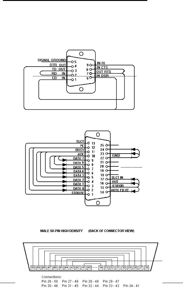
Loop Back Connectors
In order to run the RS232 serial port, parallel port, and SCSI port self-test, a loop back connector is needed. The loop back may be placed on either the OmniBook port or at the end of the corresponding cable. This feature is also helpful in diagnosing a defective serial, parallel, or SCSI cable.
Loop back connectors may be purchased or can easily be constructed. The following illustrations identify the correct pin-out configurations for the serial, parallel, and scsi loop back connectors.
Figure 5 - Serial Loop Back Connector
Figure 6 - Parallel Loop Back Connector
10
Figure 7 - SCSI Loop Back Connector
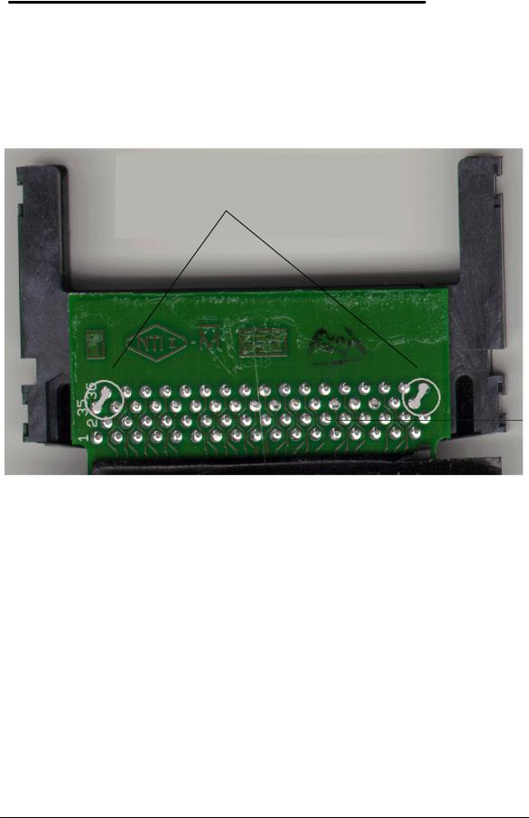
PCMCIA Type III extender card
The PCMCIA test that makes use of SyCard Technology’s SyCard also requires an extender card modified with two jumpers or with solder bridges. In order for the Sycard to be detected, CD1and GND must be shorted together, and GND with CD2must also be shorted together.
These are both pairs of endmost pins on the extender. Once these jumpers or solder bridges are added, the SyCard will successfully be detected and the SyCard tests can be performed. See Figure 8.
Solder Bridges
Figure 8 - SyCard Solder Bridges
11
 Loading...