


omnibook 2000
Service Manual
HP OmniBook 2000, 5500, and 5700

Notice
In a continuing effort to improve the quality of our products,
technical and environmental information in this document is
subject to change without notice.
Hewlett-Packard makes no warranty of any kind with regard to
this material, including, but not limited to, the implied warranties
of merchantability and fitness for a particular purpose. HewlettPackard shall not be liable for errors contained herein or for
incidental or consequential damages in connection with the
furnishing, performance, or use of this material.
Hewlett-Packard assumes no responsibility for the use or
reliability of its software on equipment that is not furnished by
Hewlett-Packard.
As an ENERGY STAR partner, HP has determined that these
products meet the ENERGY STAR guidelines for energy
efficiency.
All Certifications may not be completed at product introduction.
Please check with your HP reseller for certification status.
This equipment is subject to FCC rules. It will comply with the
appropriate FCC rules before final delivery to the buyer.
ENERGY STAR is a service mark of the U.S. Environmental
Protection Agency. IBM and OS/2 are registered trademarks
and TrackPoint is a trademark of International Business
Machines Corporation. Pentium and the Intel Inside logo are
registered trademarks and MMX is a trademark of Intel
Corporation. Photo CD is a registered trademark of Kodak
Corporation. Microsoft, MS-DOS, and Windows are registered
trademarks, and the Genuine Microsoft Products logo is a
trademark of Microsoft Corporation in the United States of
America and in other countries. Sound Blaster is a trademark of
Creative Technology Ltd.
Hewlett-Packard Company 1997.
All Rights Reserved. Reproduction, adaptation, or translation
without prior written permission is prohibited except as allowed
under copyright laws.
Printed in U.S.A.
5965-0262

Table of Contents
List of Figures............................................................................................................................. iv
List of Tables............................................................................................................................... v
Introduction ................................................................................................................................ vi
Product Overview........................................................................................................................ 9
What’s New ...........................................................................................................................10
Product Features ................................................................................................................... 11
Product at a Glance...............................................................................................................14
Product Comparisons............................................................................................................. 19
Troubleshooting......................................................................................................................... 25
Power-On Self-Test ............................................................................................................... 26
Beep Codes........................................................................................................................ 26
Display Codes ....................................................................................................................27
OmniBook Diagnostics...........................................................................................................29
Running diagnostics ........................................................................................................... 29
User Interface.....................................................................................................................30
Special test hardware requirements....................................................................................31
Loop Back Connectors........................................................................................................32
Details on Individual Diagnostic Tests ................................................................................33
Test All ........................................................................................................................... 33
Display - (DISP.COM).....................................................................................................33
CPU - (CPU.EXE)...........................................................................................................34
RAM - (RAM.COM)......................................................................................................... 34
ROM - (ROM.EXE) ......................................................................................................... 34
PCMCIA - (PCMCIA.COM) .............................................................................................35
Internal IR - (FIRTEST.EXE)...........................................................................................35
Full 2 Unit IR Test - (FIRTEST.EXE)...............................................................................36
RS-232 Port - (RS232.COM)...........................................................................................37
Printer Port - (LPT.COM) ................................................................................................38
Hard Disk - (HDC.EXE)................................................................................................... 38
Floppy Disk - (FDC.EXE) ................................................................................................39
Battery - (BATTERY.EXE) ..............................................................................................39
Audio - (AUDIO.EXE)......................................................................................................39
Microphone - (MIKE.EXE)............................................................................................... 40
Joystick - (JOYSTICK.EXE)............................................................................................40
Icon LCD - (ICON.EXE) ..................................................................................................41
Keyboard - (KEYBD.EXE)...............................................................................................41
Pointing Device - (MOUSE.EXE) .................................................................................... 42
CD-ROM - (CDROM.EXE)..............................................................................................42
SCSI - (SCSI.EXE) ......................................................................................................... 43
Fan - (FAN.EXE).............................................................................................................43
Desktop Management Interface (DMI).................................................................................... 45
Description of DMI ..............................................................................................................45
Contents of the DMI Package.............................................................................................45
System Configuration Utility ...................................................................................................48
Main Configuration Screen.................................................................................................48
System Menu .....................................................................................................................49
Passwords Menu ................................................................................................................50
Disks Menu.........................................................................................................................51
Input/Output Menu..............................................................................................................52
Power Menu.......................................................................................................................54
Exit Menu........................................................................................................................... 56
Troubleshooting Tips..............................................................................................................57
Hardware Repair ....................................................................................................................... 63
ii

Battery (End User Replaceable).............................................................................................64
Memory (End User Replaceable) ...........................................................................................65
Hard Disk Drive (End User Replaceable) .............................................................................. 67
Floppy Disk Drive (End User Replaceable) ............................................................................ 69
Small Parts (End User Replaceable)...................................................................................... 70
Expansion Door - F1125-60920..........................................................................................70
Display Contrast/Brightness Slider Button - F1371-60917................................................... 70
Door, Flash BIOS - F1371-60901 .......................................................................................70
Hard Drive Security Cover - F1320-40001.......................................................................... 70
I/O Door - F1350-60910 (OB2000 & OB5700), F1320-60928 (OB5500 only) ...................... 70
Memory Cover - F1320-60927 ............................................................................................70
PCMCIA Button Assembly - F1320-60949..........................................................................70
Plastic Feet - F1320-60929.................................................................................................70
Printer Port Door - F1125-60918......................................................................................... 70
Rubber Feet - F1320-60957................................................................................................70
Trackpoint Cap - F1320-60971.........................................................................................70
Display (HP Authorized Service Providers Only)....................................................................71
Display Labels....................................................................................................................74
Keyboard (HP Authorized Service Providers Only) ................................................................76
Icon Board (PCA PB-ICON) (HP Authorized Service Providers Only) .................................... 79
CPU Module (HP Authorized Service Providers Only)............................................................82
Logic PCA Board (PCA PB-586/IO Bracket) (HP Authorized Service Providers Only)............85
Programmable Flash BIOS IC (HP Authorized Service Providers Only).................................89
Video Memory (OB2000 & OB5700 Only) (HP Authorized Service Providers Only) ...............91
Other Components and Accessories (HP Authorized Service Providers Only)........................93
Appendix A - Technical Specifications .......................................................................................95
Mass Storage Specifications..................................................................................................95
Hard Disk Drive..................................................................................................................95
Floppy Disk Drive...............................................................................................................96
CD-ROM Drive................................................................................................................... 96
System Resources................................................................................................................. 97
System Interrupts ...............................................................................................................97
System Memory .................................................................................................................98
System Input/Output Addresses..........................................................................................98
DMA Channels ...................................................................................................................99
Appendix B - Hewlett-Packard Password Removal Policy........................................................ 100
Appendix C - Hewlett-Packard TFT Display Quality Statement................................................ 102
Appendix D - Assembly Sub-Component Breakout..................................................................103
Appendix E - Part Numbers.....................................................................................................111
iii

List of Figures
Figure 1 - OmniBook 2000 and 5700 External Features ............................................................11
Figure 2 - OmniBook 2000 and 5700 External Features - continued..........................................12
Figure 3 - OmniBook 5500 External Features............................................................................13
Figure 4 - OmniBook 5500 External Features - continued.......................................................... 13
Figure 5 - OmniBook 2000, 5500, and 5700 Center Bay Modules..............................................14
Figure 6 - OmniBook 2000 and 5700 Exploded Diagram...........................................................15
Figure 7 - OmniBook 5500 Exploded Diagram........................................................................... 17
Figure 8 - Diagnostics User Interface.........................................................................................30
Figure 9 - Serial Loop Back Connector......................................................................................32
Figure 10 - Parallel Loop Back Connector .................................................................................32
Figure 11 - DMI Components.....................................................................................................46
Figure 12 - Main Configuration Screen......................................................................................48
Figure 13 - System Menu Screen ..............................................................................................49
Figure 14 - Passwords Menu Screen .........................................................................................50
Figure 15 - Disks Menu Screen..................................................................................................51
Figure 16 - Input/Output Menu Screen.......................................................................................52
Figure 17 - Power Menu Screen................................................................................................54
Figure 18 - Exit Menu Screen.................................................................................................... 56
Figure 19 - Removing the Battery ..............................................................................................64
Figure 20 - Removing Memory..................................................................................................65
Figure 21 - Removing the Hard Disk Drive ................................................................................67
Figure 22 - Hard Drive Case ......................................................................................................68
Figure 23 - Removing the Hard Drive Plastic Kit........................................................................68
Figure 24 - Removing the Floppy Disk Drive .............................................................................69
Figure 25 - Display Screws........................................................................................................ 72
Figure 26 - Icon Assembly Removal.......................................................................................... 72
Figure 27 - Display Cables ........................................................................................................73
Figure 28 - Display Flex Cable Position..................................................................................... 73
Figure 29 - 10.4" Display Label Placements ..............................................................................74
Figure 30 - 11.3" Display Label Placements ..............................................................................75
Figure 31 - 12.1" Display Label Placements ..............................................................................75
Figure 32 - Palmrest Assembly Removal...................................................................................76
Figure 33 - Keyboard Screws.....................................................................................................77
Figure 34 - Keyboard Removal ..................................................................................................78
Figure 35 - Upper Chassis Case Removal.................................................................................80
Figure 36 - Icon Board Removal ................................................................................................81
Figure 37 - CPU and CPU Fan Removal (OB2000 & OB5700 only)........................................... 83
Figure 38 - CPU and Heat Spreader Removal (OB5500 only) ...................................................84
Figure 39 - Additional Screw for Logic PCA Removal................................................................ 86
Figure 40 - Keyboard Shielding Plate Removal ......................................................................... 87
Figure 41 - Logic PCA Board Removal......................................................................................88
Figure 42 - Flash BIOS Door Removal......................................................................................89
Figure 43 - Flash BIOS IC Removal..........................................................................................90
Figure 44 - Replacing the Flash BIOS IC...................................................................................90
Figure 45 - Video Memory Removal..........................................................................................91
iv

List of Tables
Table 1 - Additional Resources................................................................................................... vi
Table 2 - OmniBook 2000 and 5700 Parts Identification ............................................................16
Table 3 - OmniBook 5500 Parts Identification............................................................................18
Table 4 - POST Beep Codes.....................................................................................................26
Table 5 - POST Display Codes ..................................................................................................27
Table 6 - Dianostic Interface Available Keystrokes....................................................................31
Table 7 - Diagnostic Tests that Require Special Hardware......................................................... 31
Table 8 - System Menu Settings ................................................................................................49
Table 9 - Password Menu Settings ............................................................................................51
Table 10 - Disks Menu Settings.................................................................................................52
Table 11 - Input/Output Menu Settings ......................................................................................53
Table 12 - Power Menu Settings ................................................................................................54
Table 13 - Exit Menu Settings....................................................................................................56
Table 14 - OmniBook Troubleshooting Tips...............................................................................57
Table 15 - Battery Compatibility Matrix ......................................................................................64
Table 16 - Memory Compatibility Matrix....................................................................................65
Table 17 - Hard Drive Availability Matrix ................................................................................... 67
Table 18 - Display Compatibility Matrix .....................................................................................71
Table 19 - Display Label Compatibility Matrix............................................................................ 74
Table 20 - Icon Board Compatibility Matrix................................................................................79
Table 21 - CPU Module Compatibility Matrix.............................................................................82
Table 22 - Logic PCA Compatibility Matrix ................................................................................ 86
Table 23 - Other Repairable Components and Accessories.......................................................93
Table 24 - Hard Disk Drive Specifications..................................................................................95
Table 25 - Floppy Disk Drive Specifications...............................................................................96
Table 26 - CD-ROM Drive Specifications ..................................................................................96
Table 27 - System Interrupts for the OmniBook 2000 and 5700................................................. 97
Table 28 - System Interrupts for the OmniBook 5500 ................................................................ 97
Table 29 - System Memory Map for the OmniBook 2000 and 5700...........................................98
Table 30 - System Memory Map for the OmniBook 5500........................................................... 98
Table 31 - System I/O Addresses for the OmniBook 2000 and 5700..........................................98
Table 32 - System I/O Addresses for the OmniBook 5500.........................................................99
Table 33 - DMA Channels for the OmniBook 2000 and 5700..................................................... 99
Table 34 - DMA Channels for the OmniBook 5500 .................................................................... 99
v

Introduction
This document provides reference information for the HP OmniBook 2000, 5500, and 5700. It is
intended to be used by HP-qualified service personnel to help with the installation, servicing, and
repair of these HP OmniBook PCs.
It is a self-paced guide designed to train you to install, configure, and repair the OmniBook
Notebook PC. You can follow it without having any equipment available.
The following table lists additional sources where supplementary information can be obtained.
Table 1 - Additional Resources
Resource Number/Address Comments
HP External Web http://www.hp.com/go/omnibookNo usage restriction
(http://www2.hp.com/go/omniboo
k provides a European mirror)
HP-MCD Internal Web http://webmcd.cv.hp.com Restricted to HP intranet access
only
America Online Keyword: HP Call (800) 827-6364 for
CompuServe
1
GO HP Call (800) 524-3388 for
HP Bulletin Board Service2(208) 344-1691 (US only) Refer to the latest Product
HP First (automated fax) (800) 333-1917 US and Canada
(801) 344-4809 Outside US and Canada
(800) 544-9976 Reseller support number (enter
HP Support Assist CD-
(800) 457-1762 US and Canada
ROM
(801) 431-1587 Outside US and Canada
HP MCD Service Engineer svc-eng_mcd@om.cv.hp.com Email address for service related
membership within the US
membership within the US
Support Plan for non-US BBS
numbers
outlet id number)
questions and issues
1
Baud rates = 300-28.8; Parity = E; Data bits = 7; Stop bits = 1
2
Baud rates = 300-28.8; Parity = N, Data bits = 8; Stop bits = 1
vi

vii


Product Overview
Part 1
• What’s New
• Product Features
• Product at a Glance
• Product Comparisons

What’s New
The OmniBook 2000 is the newest OmniBook in the Desktop-to-Go Notebook PC series. It has
many of the same features as the OmniBook 5700 while still maintaining a lower price. The
following list compares and contrasts the OmniBook 2000 and OmniBook 5700.
Feature OmniBook 2000 OmniBook 5700
Processor
Cache no L2 cache
Memory expandable to 128MB expandable to 128MB
Display 12.1” TFT SVGA up to 16.7M colors
Video C&T 65554 64-bit accelerated
PC Card Cardbus support Cardbus support
System Chipset Opti Viper-N+ Opti Viper-N+
Desktop
Management
Interface
Advanced
Power
Management
Off States On, suspend, resume, hibernate and
133-MHz Intel Pentium with and
without MMX technology
16-KB or 32-KB L1 cache
12.1” DSTN SVGA up to 64K colors
graphics processor with 2M video
RAM and Zoom Video enabled
Pre-installed DMI 1.1 software Pre-installed DMI 1.1 software
APM 1.2 APM 1.2
full off
Intel Pentium P55C
150 MHz and 166 MHz with MMX
technology
512-KB L2 pipeline-burst
synchronous cache
32-KB L1 cache
12.1” TFT XGA and 12.1” TFT SVGA
up to 16.7M colors
C&T 65554 64-bit accelerated
graphics processor with 2M video
RAM and Zoom Video enabled
On, suspend, resume, hibernate and
full off
10
Product Features
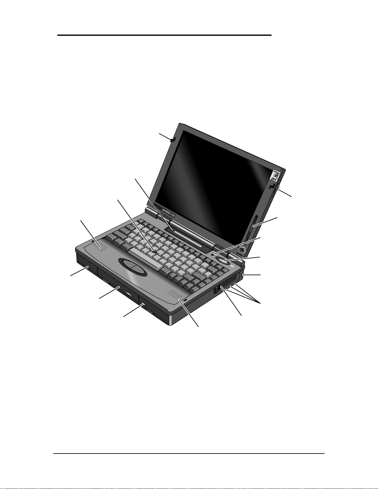
The first two illustrations (Figure 1 and Figure 2) point out the key external features of the
OmniBook 2000 and 5700. The second two illustrations (Figure 3 and Figure 4) point out the key
external features of the OmniBook 5500. Figure 5 on page 14 shows the accessories that can be
used in the center bay of the OmniBook 2000, 5500, and 5700.
Latch
Status
panel
Pointing
device
Latch
Speaker
Hard
drive
Floppy drive
(center bay
accessory slot)
Figure 1 - OmniBook 2000 and 5700 External Features
Battery
Speaker
Display
control(s)
Microphone
On/Suspend
button
Kensington lock
Audio
jacks
PC card
slots
11
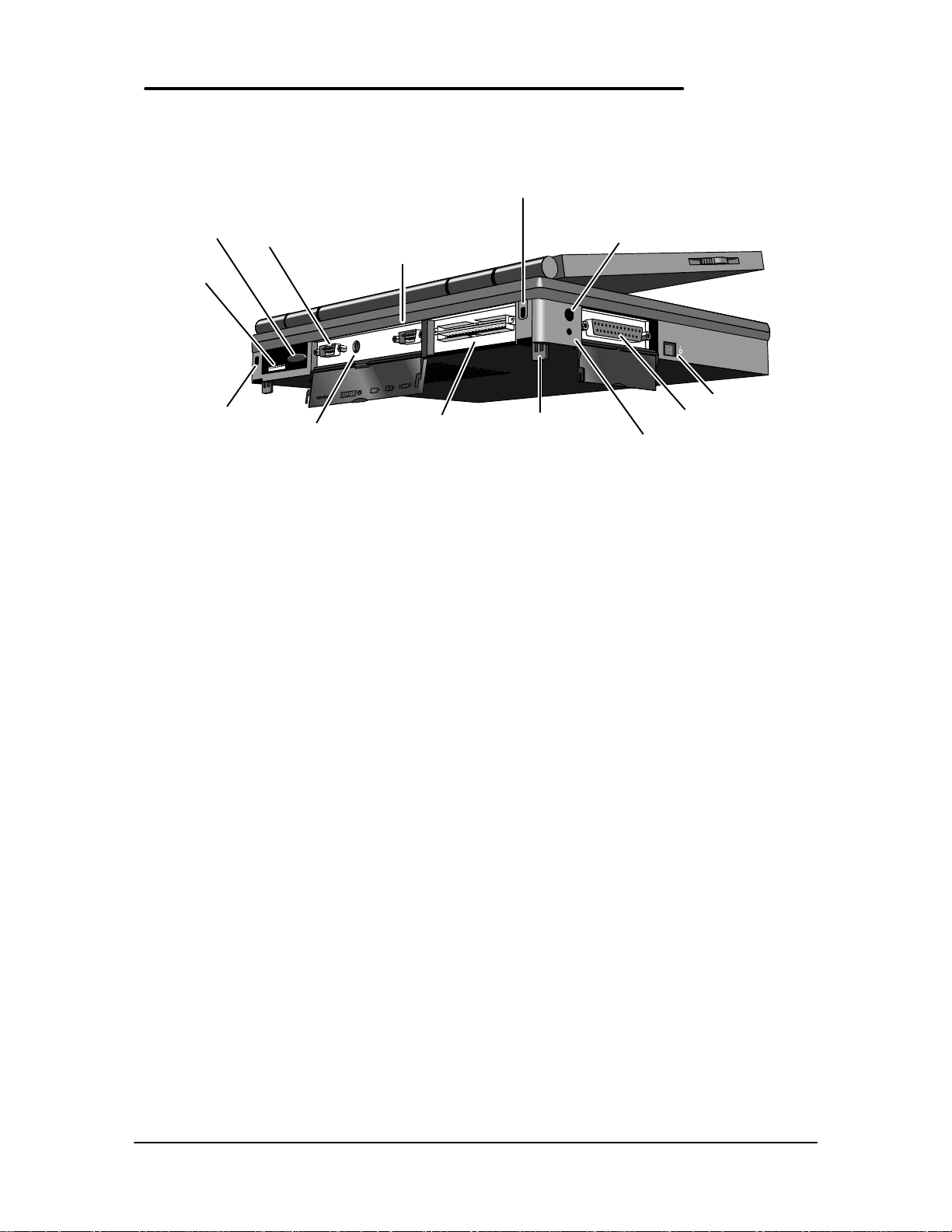
IR port
MIDI/Joystick
port
Kensington
lock
Figure 2 - OmniBook 2000 and 5700 External Features - continued
Serial port
Mouse or
Keyboard
VGA out
Docking
port
Kensington
lock
Tilt foot
AC adapter
Reset
button
Off button
Parallel
port
12
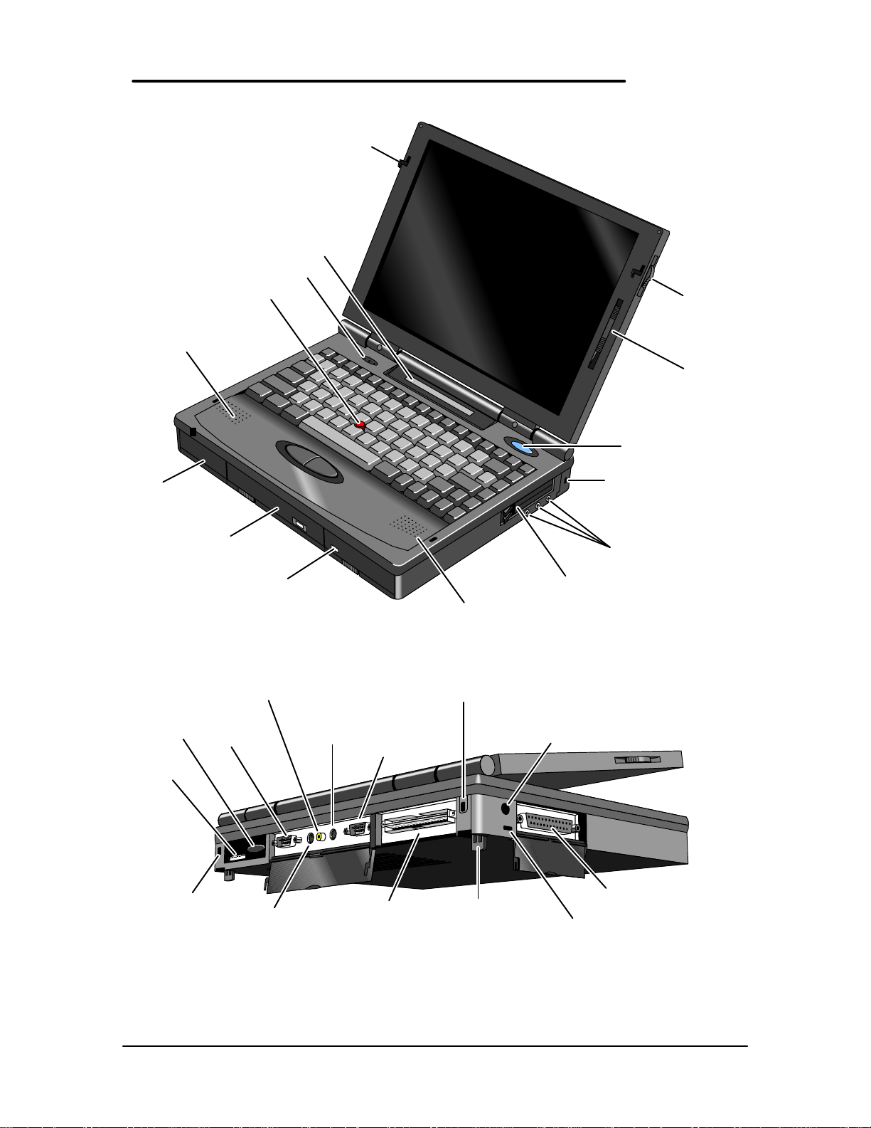
port
lock
Keyboard
button
Video out
f button
Kensington lock
IR port
MIDI/Joystick
Kensington
Serial port
VHS out
Mouse or
Latch
VGA out
Docking
port
Tilt foot
AC
Parallel
port
Reset
Figure 3 - OmniBook 5500 External Features
Pointing device
Speaker
Hard drive
Floppy drive
(center bay
accessory slot)
Figure 4 - OmniBook 5500 External Features - continued
Status panel
Microphone
Battery
Speaker
Latch
Display
control
On/Suspend/Of
Kensington lock
Audio jacks
PC card slots
13
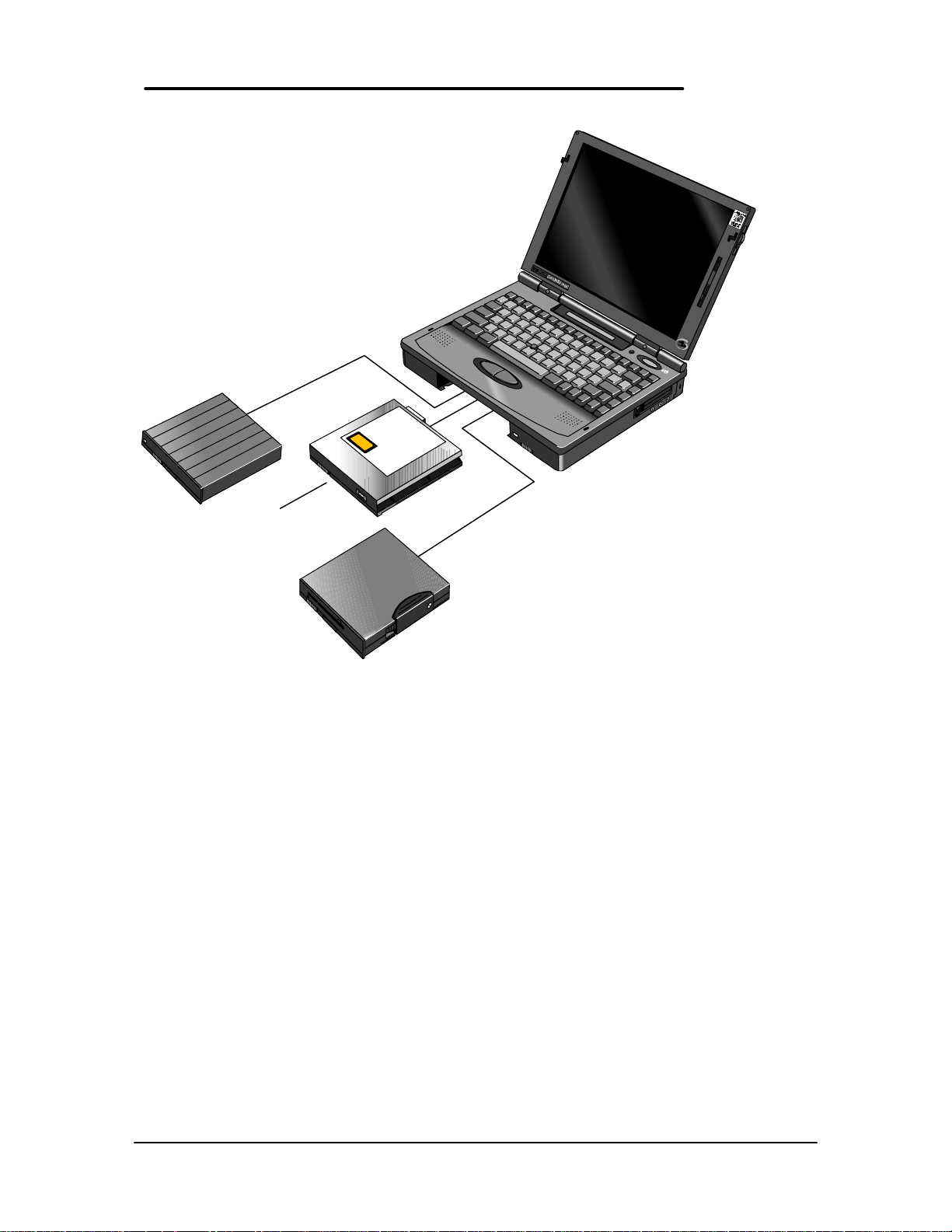
High-capacity
battery
CD-ROM
drive
Floppy disk
drive
Figure 5 - OmniBook 2000, 5500, and 5700 Center Bay Modules
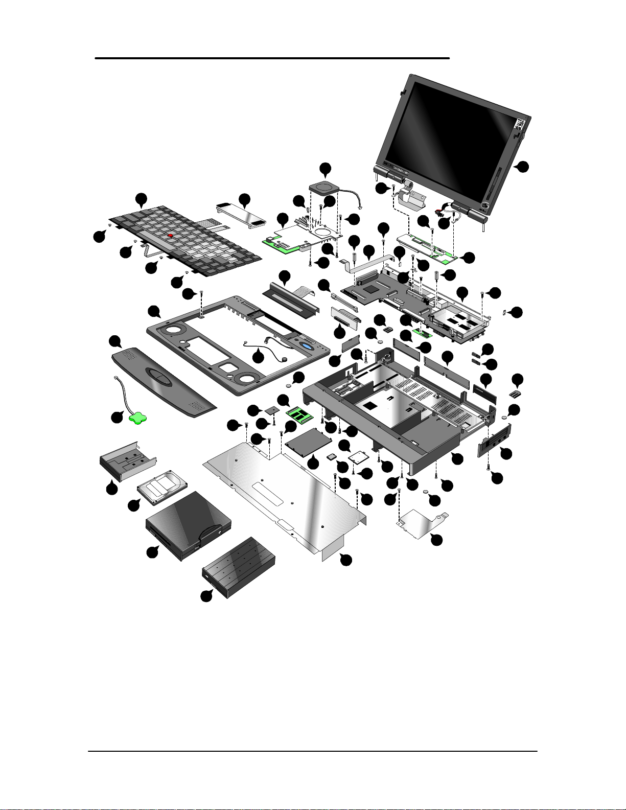
Product at a Glance
PENTIUM
14
22
28
4
44
8
45
23
46
27
15
50
46
13
46
51
11
46
37
43
16
43
26
41
17
5
35
1
43
25
39
14
40
38
33
12
34
43
7
21
38
45
47
44
10
35
36
43
43
18
6
32 52
37
38
38
37
38
37
43
44
30
48
29
9
19
24
42
35
3
31
20
43
18
31
32
35
2
44
49
Figure 6 - OmniBook 2000 and 5700 Exploded Diagram
15
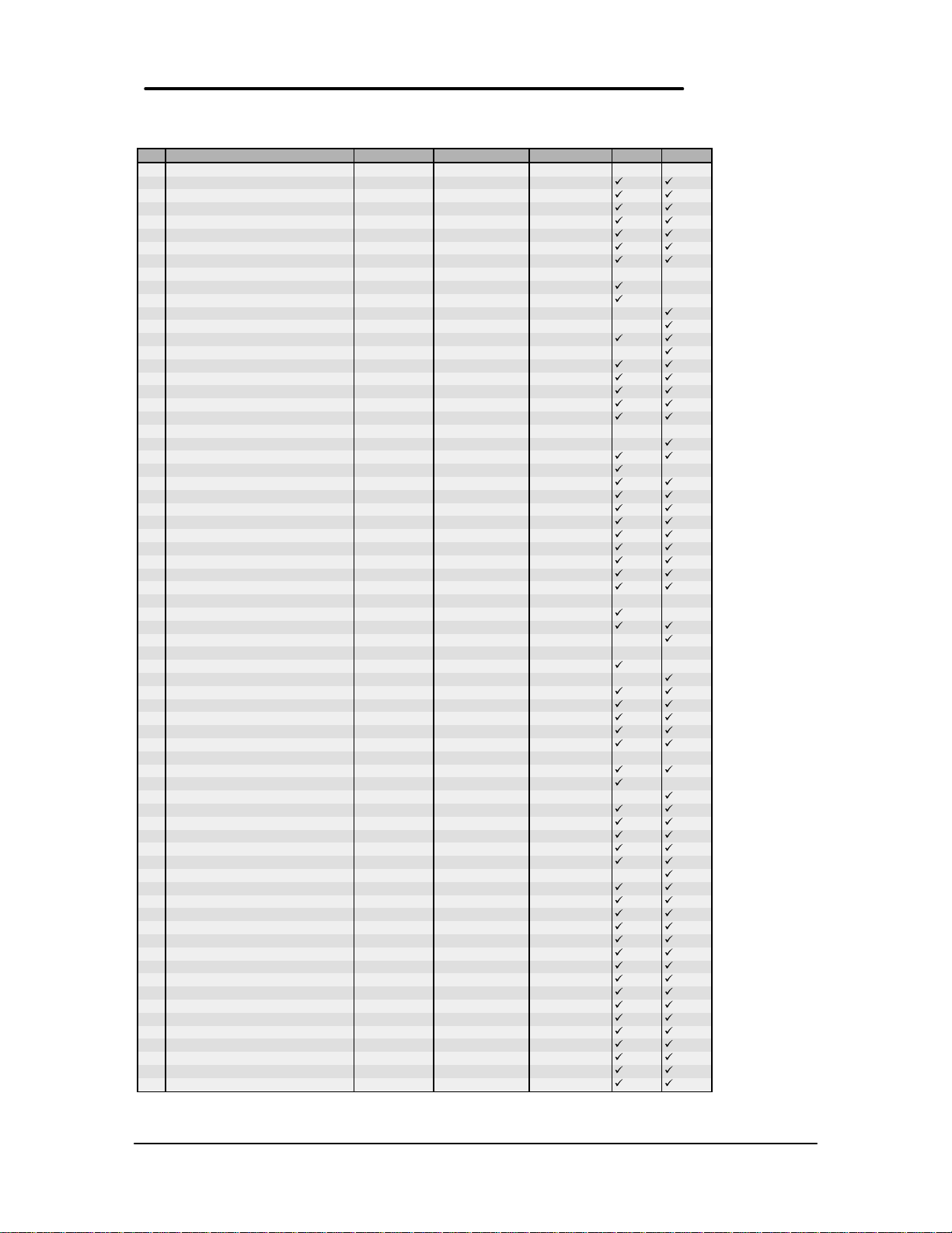
Table 2 - OmniBook 2000 and 5700 Parts Identification
Description Part Number Exchange Part # User Replace. OB5700 OB2000
1 Memory Module
8MB RAM F1134-60901 F1134-69001 Y
16MB RAM F1135-60901 F1135-69001 Y
32MB RAM F1136-60901 F1136-69001 Y
64MB RAM F1335-60901 F1335-69001 Y
2 Bezel F1320-60958 N
3 Card Bus Bracket F1350-60916 N
4 CPU Fan F1350-60906 N
5 CPU Module
CPU Module/150C F1350-60904 F1350-69004 N
CPU Module/166C F1350-60905 F1350-69005 N
CPU Module/P54C-133 F1371-60908 F1371-69008 N
CPU Module/P55C-133 (MMX) F1371-60909 F1371-69009 N
6 Dock Grounding Spring Plate F1320-60962 N
7 Door, Flash BIOS F1371-60901 Y
8 EMI Spring for LCD Hinge F1350-60913 N
9 Expansion Door F1125-60920 Y
10 FFC Cable T/B to M/B 10 PIN F1320-60950 N
11 3.5" floppy disk drive F1195-60901 Y
12 HDD-FPC Flex F1320-60961 N
13 Hard Disk Drive
HDD Drive 1.44GB F1375-60901 F1375-69001 Y
HDD Drive 2.0GB F1339-60901 F1339-69001 Y
HDD Drive 3.0GB F1348-60901 F1348-69001 Y
14 HDD PCB Bracket F1320-60965 N
15 HDD Plastic Kit F1350-60920 Y
16 HDD Security Cover F1320-40001 Y
17 Icon Assembly F1320-60918 N
18 I/O Bracket Grounding Clip F1350-60912 N
19 I/O Door F1350-60910 Y
20 IR Lens F1320-60952 N
21 KBD Shielding Plate F1320-60960 N
22 Keyboard * N
23 LCD Display
LCD Assy 12.1 TFT/X F1350-69002 F1350-69002 N
LCD Assy/SMG 12.1 TFT/S F1320-69094 F1320-69094 N
LCD Assy-12.1" DSTN F1371-60906 F1371-69006 N
24 Lower Chassis Case
25 Memory Cover Door F1320-60927 Y
26 Microphone Assembly F1081-60946 N
27 Palmrest2 Assembly F1320-60986 N
28 PCA - DC Power Supply F1350-60909 N
29 PCA PB-586/IO Bracket F1350-60901 F1350-69001 N
30 PCA PB-Icon Board
31 PCMCIA Button Assembly F1320-60949 Y
32 Plastic Foot F1320-60929 Y
33 Printer Port Door F1125-60918 Y
34 Prog Flash IC, BIOS F1371-60903 N
35 Rubber Foot F1320-60957 Y
36 Screw - BIOS Door F1371-60902 Y
37 Screw - CPU M2 X 4L F1320-60963 N
38 Screw - CPU M2.6 X 6L F1081-60942 N
39 Screw - FTB M2.6x10L F1350-60925 N
40 Screw - FTB M2.6x8L F1350-60926 N
41 Screw - HDD Door F1320-60919 Y
42 Screw - ISOF M2.6x6L F1350-60923 N
43 Screw - ISOP M2x6L Nyl F1350-60924 N
44 Screw - ISOP M2.6X8L NYLOK F1081-60939 N
45 Screw - ISOT M2.6x4L F1350-60927 N
46 Screw - Keyboard F1320-60920 N
47 Standoff-M2x11.75 Nyl F1350-60928 N
48 Standoff-M2x15L Nyl F1350-60929 N
49 Std Li-Ion Battery F1193-60902 Y
50 Sub Batt - NiMHd F1350-60921 N
51 Upper Chassis Case F1350-60915 N
52 Video RAM F1350-60922 N
Note, this is a partial parts list. For a complete parts list, please refer to Appendix E or the Product Support Plan.
*For a complete listing of available localized keyboards, refer to Appendix E or the Product Support Plan.
Lower Chassis Case - 5700 F1350-60914 N
Lower Chassis Case - 2000 F1371-60905 N
PCA PB-ICON/SVGA F1350-60907 N
PCA PB-ICON/XGA F1350-60908 N
PCA PB-ICON/DSTN F1371-60911 N
16
17
42
42
21
42
47
42
36
28
36
36
15
36
43
41
34
39
40
26
36
5
17
39
3
40
30
44
29
41
9
36
36
13
2
16
22
39
17
27
10
46
37
37
12
32
4
18
35
36
23
14
19
31
31
32
35
1
40
35
7
37
33
34
39
40
37
37
39
20
26
35
25
11
38
39
39
8
6
45
39
24
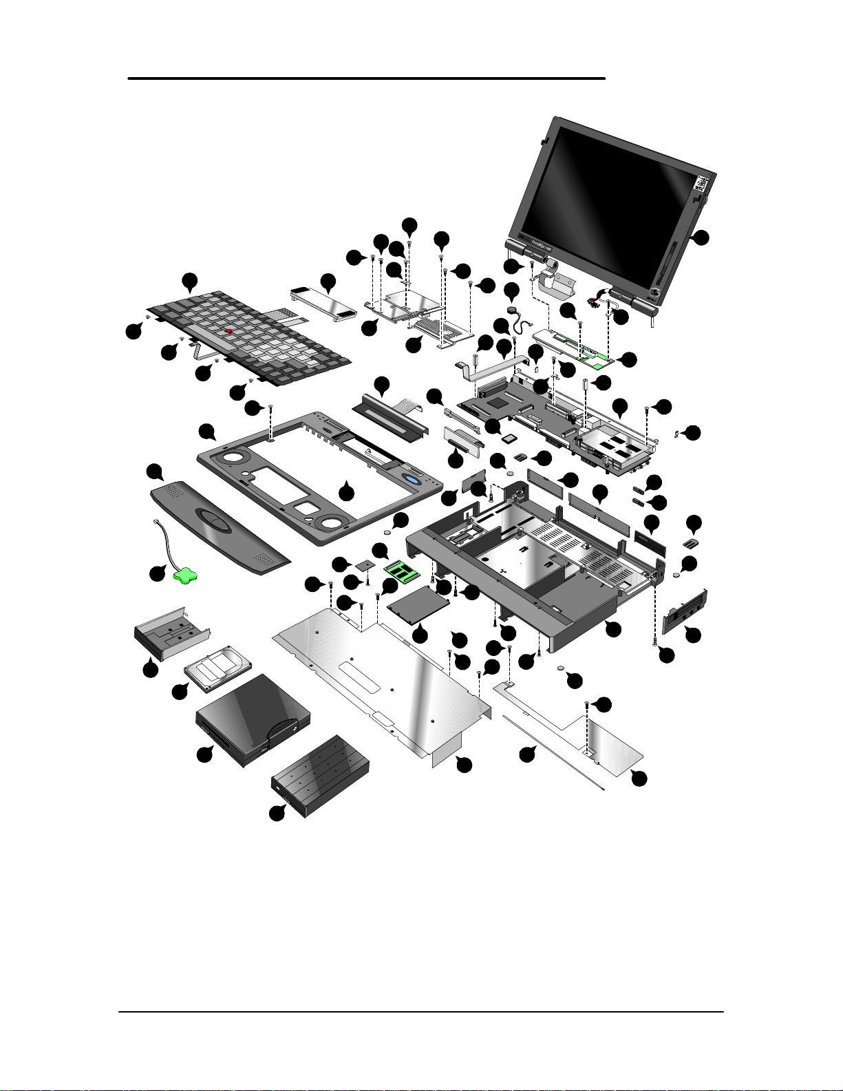
Figure 7 - OmniBook 5500 Exploded Diagram
17

Table 3 - OmniBook 5500 Parts Identification
Description Part Number Exchange Part # User Replace.
1 Bezel F1320-60958 N
2 CPU Module
3 Dock Grounding Spring Plate F1320-60962 N
4 Expansion Door F1125-60920 Y
5 FFC Cable T/B to M/B 10 PIN F1320-60950 N
6 3.5" floppy disk drive F1195-60901 Y
7 HDD-FPC Flex F1320-60961 N
8 Hard Disk Drive
9 HDD PCB Bracket F1320-60965 N
10 HDD Plastic Kit F1320-60947 Y
11 HDD Security Cover F1320-40001 Y
12 Heat Pipe F1320-60964 N
13 Heat Pipe Bracket F1320-60972 N
14 Heat Pipe Spreader F1320-60921 N
15 Heat Sink F1320-60954 N
16 Icon Assembly F1320-60918 N
17 I/O Bracket Grounding Clip F1350-60912 N
18 I/O Door F1320-60928 Y
19 IR Lens F1320-60952 N
20 KBD Shielding Plate F1320-60960 N
21 Keyboard * N
22 LCD Display
23 Lower Chassis Case F1320-60930 N
24 Memory Cover Door F1320-60927 Y
25 Memory Module
26 Microphone Assembly F1081-60946 N
27 Palmrest2 Assembly F1320-60986 N
28 PCA - DC Power Supply F1320-60925 N
29 PCA PB-586/IO Bracket F1320-60926 F1320-69026 N
30 PCA PB-Icon Board
31 PCMCIA Button Assembly F1320-60949 Y
32 Plastic Foot F1320-60929 Y
33 Printer Port Door F1125-60918 Y
34 Prog Flash IC, BIOS F1321-60907 N
35 Rubber Foot F1320-60957 Y
36 Screw - CPU M2 X 4L F1320-60963 N
37 Screw - CPU M2.6 X 6L F1081-60942 N
38 Screw - HDD Door F1320-60919 Y
39 Screw - ISOP M2.0x6.0L Nylok F1350-60924 N
40 Screw - ISOP M2.6X8L Nylok F1081-60939 N
41 Screw - M2.6x4.0L F1350-60927 N
42 Screw - Keyboard F1320-60920 N
43 Standoff-M2x11.75 Nyl F1320-60951 N
44 Standoff-M2x15L Nyl F1320-60955 N
45 Std Li-Ion Battery F1193-60902 Y
46 Sub Battery 4.8v F1081-60925 N
47 Upper Chassis Case F1320-60931 N
Note, this is a partial parts list. For a complete parts list, please refer to Appendix E or the Product Support Plan.
*For a complete listing of available localized keyboards, refer to Appendix E or the Product Support Plan.
CPU Module/100C F1320-60901 F1320-69001 N
CPU Module/120C F1320-60902 F1320-69002 N
CPU Module/133C F1320-60903 F1320-69003 N
HDD Drive 810MB F1191-60901 F1191-69001 Y
HDD Drive 1.35GB F1192-60901 F1192-69001 Y
HDD Drive 2.0GB F1339-60901 F1339-69001 Y
LCD Assy 10.4” TST/S F1320-60904 F1320-69004 N
LCD Assy 11.3” DSTN/S F1320-60905 F1320-69005 N
LCD Assy 12.1" TFT/S F1320-60906 F1320-69006 N
LCD Assy-SMG 12.1" TFT/S F1320-60994 F1320-69094 N
8MB RAM F1134-60901 F1134-69001 Y
16MB RAM F1135-60901 F1135-69001 Y
32MB RAM F1136-60901 F1136-69001 Y
PCA PB-ICON F1320-60924 N
PCA PB-ICON/SMG F1320-60993 N
18

Product Comparisons
HP OmniBook 5700 HP OmniBook 5500 HP OmniBook 2000
Size Closed
Weight
Processor
Bus Architecture
Cache
Display Size
Display
Resolution
Video Bus
Video RAM
VGA-out Support
29.5 x 22.6 x 4.9 cm
(11.6 x 8.9 x 1.93 in)
3.27 kg (7.2 lb) 3.4 kg (7.5 lb) 3.27 kg (7.2 lb)
166- or 150-MHz Intel Pentium
with MMX technology
32-bit PCI bus 32-bit PCI bus 32-bit PCI bus
512-KB burst-synchronous L2
cache
12.1-inch TFT 10.4- or 12.1-inch diagonal
XGA TFT 1024 x 768 x 64k
colors
SVGA TFT 800 x 600 x 16.7M
colors
PCI local bus video PCI local bus video PCI local bus video
2-MB video RAM 1-MB video RAM 2-MB video RAM
XGA-out supports up to 1024 x
768 x 64k colors
29.5 x 22.6 x 4.9 cm
(11.6 x 8.9 x 1.93 in)
100-, 120-, or 133-MHz Intel
Pentium processor
256-KB external L2 cache no L2 cache
TFT
11.3-inch diagonal DSTN
SVGA TFT 800 x 600 x 64K
colors
SVGA DSTN 800 X 600 X 256
colors
XGA-out supports up to 1024 x
768 x 256 colors
29.5 x 22.6 x 4.9 cm
(11.6 x 8.9 x 1.93 in)
133-MHz Intel Pentium with
and without MMX technology
12.1-inch diagonal TFT
12.1-inch diagonal DSTN
SVGA TFT 800 x 600 x 16.7M
colors
SVGA DSTN 800 x 600 x 64K
colors
XGA-out supports up to 1024 x
768 x 64k colors
Video Controller
Power
Battery Type
Battery Life
Recharge Rate
Advanced Power
Management
Chips and Technology 65554
controller (64-bit)
AC adapter 100 to 240 Vac (50
to 60 Hz) input; 12 Vdc, 3.3 A
output
14.4-Vdc, 2.5-AH rechargeable
Lithium-Ion battery
Optional, 14.4-Vdc, 3.75-AH
enhanced Lithium Ion battery
Up to 2.5 hours with one LiIon
battery (enhanced LiIon battery
adds up to 3.75 hours)
Battery recharges to high level
in 4 hours using AC adapter
while PC is on or off
Instant-on maintains computer
in ready-to-work state for weeks
on a full charge; returns you to
Chips and Technology 65548
controller (32-bit)
AC adapter 100 to 240 Vac (50
to 60 Hz) input; 12 Vdc, 3.3 A
output
14.4-Vdc, 2.5-AH rechargeable
Lithium-Ion battery
Optional, 14.4-Vdc, 3.75-AH
enhanced Lithium Ion battery
Up to 2.5 hours with one LiIon
battery (enhanced LiIon battery
adds up to 3.75 hours)
Battery recharges to high level
in 4 hours using AC adapter
while PC is on or off
Instant-on maintains computer
in ready-to-work state for
weeks on a full charge; returns
you to your application or file
Chips and Technology 65554
controller (64-bit)
AC adapter 100 to 240 Vac (50
to 60 Hz) input; 12 Vdc, 3.3 A
output
14.4-Vdc, 2.5-AH rechargeable
Lithium-Ion battery
Optional, 14.4-Vdc, 3.75-AH
enhanced Lithium Ion battery
Up to 2.5 hours with one LiIon
battery (enhanced LiIon battery
adds up to 3.75 hours)
Battery recharges to high level
in 4 hours using AC adapter
while PC is on or off
Instant-on maintains computer
in ready-to-work state for
weeks on a full charge; returns
you to your application or file
19

HP OmniBook 5700 HP OmniBook 5500 HP OmniBook 2000
Removable
Modules
Hard Disk Drive
Floppy Disk Drive
CD-ROM Drive
Memory
your application or file instantly
2-minute low-battery warning
• Floppy disk drive
internal/external (can be
replaced with a second battery
or CD ROM drive)
• Hard disk drive
• RAM
• Battery
3.0-billion-byte or 2.0-billionbyte hard drives
Internal 3.5-inch, 1.44-MB,
standard; swaps with CD-ROM
or enhanced battery; usable
externally
Optional, internal, 10x Optional, internal, 10x Optional, internal, 10x
Self-refreshed FPM DRAM
16 or 32-MB models,
expandable to 128 MB
8-, 16-, 32-, and 64-MB RAM
modules available
instantly
2-minute low-battery warning
• Floppy disk drive
internal/external (can be
replaced with a second
battery or CD ROM drive)
• Hard disk drive
• RAM
• Battery
810-MB, 1.35-GB, or 2.0GB
hard disks
Internal 3.5-inch, 1.44-MB,
standard; swaps with CD-ROM
or enhanced battery; usable
externally
Self-refreshed FPM DRAM
8 or 16-MB models,
expandable to 64 MB
8-, 16-, and 32-MB RAM
modules available
instantly
2-minute low-battery warning
• Floppy disk drive
internal/external (can be
replaced with a second
battery or CD ROM drive)
• Hard disk drive
• RAM
• Battery
1.44-billion-byte or 2.0-billionbyte hard drives
Internal 3.5-inch, 1.44-MB,
standard; swaps with CD-ROM
or enhanced battery; usable
externally
Self-refreshed FPM DRAM
16 or 32-MB models,
expandable to 128 MB
8-, 16-, 32-, and 64-MB RAM
modules available
Audio
IO Ports
PCMCIA
16-bit with Sound Blaster Pro
and MIDI support
Stereo sound via two built-in
speakers
• 9-pin, 115,200-bps, RS-232
port
• 25-pin bidirectional ECP/EPP
parallel port
• XGA-out (up to 1024 x 768 x
64K)
• Fast-IR-IRDA compliant @
4Mbps
• Expansion bus connector
• PS/2 keyboard/mouse port
• Headphone/stereo-out port
• Stereo-in and microphone
ports
• MIDI/joystick port
One Type III PCMCIA slot (or
use as two Type II slots) with
3.3-V or 5-V support
Zoomed video support for lower
slot
CardBus support (both slots)
16-bit with Sound Blaster Pro
compatible and MIDI support
Stereo sound via two built-in
speakers
• 9-pin, 115,200 - b/s, RS-232
port
• 25-pin bidirectional ECP/EPP
parallel port
• XGA-out (up to 1024 x 768 x
256)
• Fast-IR-IRDA compliant @
4Mbps
• Expansion bus connector
• NTSC/PAL video-out port
(RCA and SVideo)
• PS/2 keyboard/mouse port
• Headphone/stereo-out port
• Stereo-in and microphone
ports
• MIDI/joystick port
One Type III PCMCIA slot (or
use as two Type II slots) with
3.3-V or 5-V support.
16-bit with Sound Blaster Pro
and MIDI support
Stereo sound via two built-in
speakers
• 9-pin, 115,200-bps, RS-232
port
• 25-pin bidirectional ECP/EPP
parallel port
• XGA-out (up to 1024 x 768 x
64K)
• Fast-IR-IRDA compliant @
4Mbps
• Expansion bus connector
• PS/2 keyboard/mouse port
• Headphone/stereo-out port
• Stereo-in and microphone
ports
• MIDI/joystick port
One Type III PCMCIA slot (or
use as two Type II slots) with
3.3-V or 5-V support
Zoomed video support for
lower slot
CardBus support (both slots)
Docking
20
Optional docking system with
one PCI/ISA and one ISA slot,
Optional docking system with
one PCI/ISA-and one ISA slot,
Optional docking system with
one PCI/ISA-and one ISA slot,

HP OmniBook 5700 HP OmniBook 5500 HP OmniBook 2000
Pre-installed
Software
parallel, serial, XGA-out (up to
1024 x 768 x 64k), keyboard,
PS/2 mouse, MIDI/joystick,
audio and SCSI-2 ports.
Optional port replicator with
parallel, serial, video-out,
keyboard, PS/2 mouse,
MIDI/joystick, and audio ports
Microsoft Windows for
Workgroups 3.11 and MSDOS 6.22 co-loaded with
Microsoft Windows 95*
Windows 95-compatible Plug
and Play BIOS
Advanced Power Management
1.2
DMI 1.1 under Windows 95
with TopTools
HP PIM and Financial
Calculator
On-line documentation
parallel, serial, XGA-out (up to
1024 x 768 x 256), keyboard,
PS/2 mouse, MIDI/joystick,
audio and SCSI-2 ports.
Microsoft Windows for
Workgroups 3.11 and MSDOS 6.22 co-loaded with
Microsoft Windows 95*
Windows 95-compatible Plug
and Play BIOS
Advanced Power Management
1.1
HP PIM and Financial
Calculator
On-line documentation
parallel, serial, XGA-out (up to
1024 x 768 x 64K), keyboard,
PS/2 mouse, MIDI/joystick,
audio, and SCSI-2 ports.
Optional port replicator with
parallel, serial, video-out,
keyboard, PS/2 mouse,
MIDI/joystick, and audio ports.
Microsoft Windows for
Workgroups 3.11 and MSDOS 6.22 co-loaded with
Microsoft Windows 95*
Windows 95-compatible Plug
and Play BIOS
Advanced Power Management
1.2
DMI 1.1 under Windows 95
with TopTools
HP PIM and Financial
Calculator
On-line documentation
Security Features
Warranty
*(Note: Upon first boot, the end user must make a ONE-TIME selection between Windows 95 and Windows for Workgroups.
Later, if the end user desires the rejected operating system, the end user will need to acquire and pay for such product as a
separate transaction.)
• 2-level password protection
• Hardware-based hard drive
password
• Electronic serial number in
CMOS accessible through
DMI
• PC ID (tattooing)
• Kensington lock slots
3-year return-to HP for repair
(1-year on battery and
accessories)
• 2-level password protection
• PC ID (tattooing) and
serialization
• Drive lock
• Kensington lock slots
3-year return-to-HP for repair
for premium models; 1-year
return-to-HP for VL's (1-year on
battery and accessories)
• 2-level password protection
• Hardware-based hard drive
password
• Electronic serial number in
CMOS accessible through
DMI
• PC ID (tattooing)
• Kensington lock slots
3-year return-to HP for repair
(1-year on battery and
accessories)
21


Part 2
Troubleshooting
• Power-On Self-Test
• OmniBook Diagnostics
• Desktop Management Interface
• System Configuration Utility
• Troubleshooting Tips
Power-On Self-Test
The OmniBook 2000, 5500, and 5700 BIOS includes a Power-On Self-Test (POST) facility that
tests a number of hardware and firmware items in the unit at each cold-start (BOOT or RESET).
The OmniBook self-test alone should not be used to diagnose a hardware problem. If the selftest results are absolutely clear and repeatable, confirm the results with at least two other nonself-test troubleshooting tools.
Within POST, there are three kinds of messages:
• Error Messages – These messages appear when there is a failure in hardware,
software, or firmware.
• Informational Messages – These messages provide information to the user but
require no action.
• Beep Codes – This kind of warning sounds when POST errors occur and the screen
is not yet available.
Beep Codes
These multiple beep codes indicate a failure in a simple test of:
• a portion of base memory
• flash BIOS checksum
• a portion of conventional memory
• a portion of extended memory
If the unit fails to boot
• all accessories are removed, including:
memory, floppy drive, docking station, modems and other PC Cards, printers,
external displays, pointing devices, and keyboard
• clean AC power is provided (no "chained" battery chargers or auto adapters), and
press reset.
If the unit still fails to boot, it requires service.
Beep codes are used to identify a POST error that occurs when the screen is not available.
Once the screen is operating, diagnostic messages are reported to the screen. There are beep
codes for both fatal and nonfatal system board errors.
Table 4 - POST Beep Codes
Beep Code Description
S-S-S-P-S-S-L-P The DMA page registers are faulty.
S-S-S-P-S-L-S-P The refresh circuitry is faulty
S-S-S-P-S-L-L-P The ROM checksum is incorrect
S-S-S-P-L-S-S-P The CMOS RAM test failed
S-S-S-P-L-S-L-P The DMA controller is faulty
S-S-S-P-L-L-S-P The interrupt controller failed
S-S-S-P-L-L-L-P The 8042 keyboard controller failed
S-S-L-P-S-S-S-P No video adapter was found
S-S-L-P-S-S-L-P No RAM installed. No message is displayed.
26

Display Codes
There are a number of Power On Self Test (POST) tests that are performed after the Beep Code
tests. Failure of one or more of these tests will result in a displayed failure code (such as
03044). It is extremely important not to interpret a failure code immediately as a hardware
failure. The failure should be confirmed with a clean boot. A clean boot is defined as pressing
the reset button after removing all accessories (including memory, floppy drive, modems, PC
cards, and printers) and providing a reliable power source. Note, make sure the display is
adjusted to be visible.
Table 5 - POST Display Codes
Message Possible Cause
CLOCK NOT TICKING CORRECTLY The real time clock is not ticking.
COLOR/MONO SWITCH INCORRECT The COLOR/MONO switch on the system
board is incorrect for the installed
hardware.
CMOS CHECKSUM INVALID - RUN SCU CMOS RAM information has been
corrupted and needs to be reinitialized via
the System Configuration Utility.
CMOS FAILURE - RUN SCU CMOS RAM has lost power and needs to
be reinitialized via the System
Configuration Utility.
FLOPPY CONTROLLER FAILED The floppy controller failed to respond to
the reset command. Power down the
system and check all appropriate
connections. It the floppy controller
continues to fail, you may need to replace
it.
FLOPPY DISK TRACK 0 FAILED The floppy drive cannot read track 0 of
the floppy disk in the drive. Try another
diskette. If the problem persists, you may
need to replace the floppy drive.
FLOPPY INFORMATION INVALID - RUN SCU The drive parameters stored in CMOS do
not match the floppy drives detected in
the system.
HARD DISK CONTROLLER ERROR The hard disk controller failed to respond
to the reset command. Possible
solutions: 1) Check the drive parameters.
2) Power down the system and check all
appropriate connections. If the problem
persists, you may need to replace the
hard disk controller.
HARDWARE INFO DOES NOT MATCH VIDEO
CARD - RUN SCU
KEYBOARD CONTROLLER FAILURE The keyboard failed the self-test
KEYBOARD FAILURE The keyboard failed to respond to the
MACHINE IS LOCKED - TURN KEY The system will not continue the boot
The video adapter type specified in
CMOS RAM does not match the installed
hardware.
command. Check to see if the keyboard
controller is properly installed. If the
problem continues, replace the controller.
RESET ID Command.
27

Message Possible Cause
sequence until you insert the key into the
key lock and turn it.
NO BOOTABLE FLOPPY DRIVE 0 INSTALLED No bootable floppy drive was detected.
Possible solutions: 1) Power down the
system and check all appropriate
connections, cables, etc. 2) In
configurations where no floppy drive is
installed, run System Configuration Utility
and make sure the diskette drive
configuration item is set to "None". 3)
Replace the diskette drive if necessary.
NO INTERRUPTS FROM TIMER 0 The periodic timer interrupt is not
occurring.
RAM PARITY ERROR AT LOCATION xxxx A RAM parity error occurred at the
specified (hexadecimal) location.
ROM AT xxxx (LENGTH YYYY) WITH NON-ZERO
CHECKSUM (zz)
TIME/DATE CORRUPT - RUN SCU The time and date stored in the real time
UNEXPECTED AMOUNT OF MEMORY - RUN SCU The amount of memory detected by
CMOS RAM TEST FAILED A walking built test of CMOS RAM
DMA CONTROLLER FAULTY A sequential read/write of the transfer
FAULTY DMA PAGE REGISTERS A walking bit read/write of the 16 DMA
FAULTY REFRESH CIRCUIT A continuous read/write test of port 61h
INTERRUPT CONTROLLER FAILED A sequential read/write of various
ROM CHECKSUM INCORRECT A checksum of the ROM BIOS does not
An illegal adapter ROM was located at the
specified address. An external adapter
(such as a video card) may be causing a
conflict.
clock have been corrupted, possibly by a
power loss.
POST does not match the amount
specified in CMOS RAM.
locations 0E (Hex) - 3F (Hex) failed.
count and transfer address registers within
the primary and secondary DMA
controllers failed.
controller page registers starting at
location 80 Hex failed.
found that bit 4 (Refresh Detect) failed to
toggle within an allotted amount of time.
Interrupt Controller registers failed.
match the byte value at F000:FFFF.
28
 Loading...