


 Loading...
HP ProLiant ML100 Series Server
User Guide
for HP ProLiant ML110 G6 and HP ProLiant ML150 G6 Servers
Abstract
This document is for the person who installs, administers, and troubleshoots servers and storage systems. HP assumes you are qualified in the servicing of computer equipment and trained in recognizing hazards in products with hazardous energy levels.
Part Number: 501528-006
April 2012
Edition: 6
© Copyright 2009, 2012 Hewlett-Packard Development Company, L.P.
The information contained herein is subject to change without notice. The only warranties for HP products and services are set forth in the express warranty statements accompanying such products and services. Nothing herein should be construed as constituting an additional warranty. HP shall not be liable for technical or editorial errors or omissions contained herein.
Microsoft, Windows, and Windows Server are U.S. registered trademarks of Microsoft Corporation. Bluetooth is a trademark owned by its proprietor and used by Hewlett-Packard Company under license.

Contents |
|
Operations................................................................................................................................... |
7 |
Power up the server...................................................................................................................................... |
7 |
Power down the server ................................................................................................................................. |
7 |
Remove the access panel .............................................................................................................................. |
7 |
Remove the tower bezel (ML110 G6 servers) .................................................................................................. |
8 |
Remove the tower bezel (ML150 G6 servers) .................................................................................................. |
8 |
Setup........................................................................................................................................... |
9 |
Optional installation services......................................................................................................................... |
9 |
Rack planning resources ............................................................................................................................... |
9 |
Optimum environment................................................................................................................................... |
9 |
Space and airflow requirements .......................................................................................................... |
9 |
Temperature requirements ................................................................................................................. |
10 |
Power requirements .......................................................................................................................... |
11 |
Electrical grounding requirements ...................................................................................................... |
11 |
Rack warnings ........................................................................................................................................... |
12 |
Installing hardware options ......................................................................................................................... |
12 |
Powering up and configuring the server........................................................................................................ |
12 |
Installing the operating system ..................................................................................................................... |
12 |
Registering the server.................................................................................................................................. |
12 |
Hardware options installation....................................................................................................... |
13 |
Introduction ............................................................................................................................................... |
13 |
Processor option......................................................................................................................................... |
13 |
SAS and SATA_hard drive options............................................................................................................... |
17 |
Hard drive LED cable (ML150 G6 servers and ML110 G6 Servers)................................................................. |
17 |
Removable media device option (ML110 G6 servers) .................................................................................... |
18 |
Removable media device option (ML150 G6 servers) .................................................................................... |
19 |
Memory options (ML110 G6 servers) ........................................................................................................... |
21 |
Memory subsystem architecture (ML110 G6 Servers) ........................................................................... |
21 |
Singleand dual-rank DIMMs (ML110 G6 servers)............................................................................... |
21 |
DIMM identification.......................................................................................................................... |
21 |
UDIMM maximum memory configurations (ML110 G6 servers)............................................................. |
22 |
General DIMM slot population guidelines (ML110 G6 servers) ............................................................. |
22 |
Memory options (ML150 G6 servers) ........................................................................................................... |
23 |
Memory subsystem architecture (ML150 G6 Servers) ........................................................................... |
23 |
Single-, dual-, and quad-rank DIMMs ................................................................................................. |
23 |
DIMM identification.......................................................................................................................... |
24 |
Memory configurations ..................................................................................................................... |
24 |
General DIMM slot population guidelines ........................................................................................... |
25 |
Expansion board options ............................................................................................................................ |
26 |
Installing a storage controller....................................................................................................................... |
29 |
Installing DIMMs ........................................................................................................................................ |
29 |
Battery-backed write cache battery pack option............................................................................................. |
30 |
Installing the FBWC module and capacitor pack ........................................................................................... |
33 |
HP Trusted Platform Module option .............................................................................................................. |
34 |
Installing the Trusted Platform Module board ....................................................................................... |
35 |
Contents |
3 |
Retaining the recovery key/password................................................................................................. |
37 |
Enabling the Trusted Platform Module................................................................................................. |
37 |
Software and configuration utilities ............................................................................................... |
38 |
ROM-Based Setup Utility ............................................................................................................................. |
38 |
Using RBSU ..................................................................................................................................... |
38 |
Auto-configuration process ................................................................................................................ |
38 |
Boot options .................................................................................................................................... |
39 |
BIOS Serial Console......................................................................................................................... |
39 |
Array Configuration Utility .......................................................................................................................... |
39 |
Option ROM Configuration for Arrays.......................................................................................................... |
40 |
HP Insight Diagnostics ................................................................................................................................ |
40 |
Management tools...................................................................................................................................... |
41 |
ROMPaq utility................................................................................................................................. |
41 |
Lights-Out 100i technology................................................................................................................ |
41 |
HP Integrated Lights-Out Virtual Floppy and CD-ROM drives ................................................................. |
41 |
USB support .................................................................................................................................... |
41 |
Remote support and analysis tools ............................................................................................................... |
42 |
HP Insight Remote Support software ................................................................................................... |
42 |
Keeping the system current.......................................................................................................................... |
42 |
Drivers ............................................................................................................................................ |
42 |
Operating System Version Support..................................................................................................... |
43 |
Subscriber's choice .......................................................................................................................... |
43 |
Embedded SATA RAID feature..................................................................................................................... |
43 |
Configuring the SATA RAID feature.................................................................................................... |
43 |
Enabling the SATA RAID feature in RBSU............................................................................................ |
43 |
Creating a RAID volume ................................................................................................................... |
44 |
Installing the embedded SATA RAID driver.................................................................................................... |
44 |
Required hardware .......................................................................................................................... |
44 |
USB diskette and CD-ROM drives ...................................................................................................... |
45 |
Creating a diskette image ................................................................................................................. |
45 |
Installing the Embedded SATA RAID driver with a USB diskette drive..................................................... |
45 |
Installing the Embedded SATA RAID driver using Virtual Floppy ............................................................ |
45 |
Installing an operating system...................................................................................................................... |
46 |
Installing a supported Microsoft® Windows® OS ............................................................................... |
46 |
Installing a supported Linux OS ......................................................................................................... |
46 |
Troubleshooting .......................................................................................................................... |
47 |
Pre-diagnostic steps .................................................................................................................................... |
47 |
Important safety information .............................................................................................................. |
47 |
Symptom information........................................................................................................................ |
49 |
Preparing the server for diagnosis...................................................................................................... |
49 |
Common problem resolution.............................................................................................................. |
50 |
Troubleshooting flowcharts .......................................................................................................................... |
52 |
Start diagnosis flowchart................................................................................................................... |
53 |
General diagnosis flowchart.............................................................................................................. |
53 |
Power-on problems flowchart............................................................................................................. |
55 |
POST problems flowchart.................................................................................................................. |
57 |
OS boot problems flowchart.............................................................................................................. |
59 |
Server fault indications flowchart ....................................................................................................... |
60 |
Hardware problems ................................................................................................................................... |
61 |
Power problems ............................................................................................................................... |
62 |
General hardware problems ............................................................................................................. |
63 |
Internal system problems ................................................................................................................... |
66 |
Contents |
4 |
System open circuits and short circuits ................................................................................................ |
72 |
External device problems .................................................................................................................. |
72 |
Audio problems ............................................................................................................................... |
73 |
Printer problems ............................................................................................................................... |
74 |
Mouse and keyboard problems ......................................................................................................... |
74 |
Modem problems ............................................................................................................................. |
74 |
Network controller problems ............................................................................................................. |
76 |
Software problems ..................................................................................................................................... |
78 |
Operating system problems............................................................................................................... |
78 |
Operating system updates................................................................................................................. |
79 |
Restoring to a backed-up version ....................................................................................................... |
79 |
When to reconfigure or reload software ............................................................................................. |
79 |
Linux operating systems .................................................................................................................... |
80 |
Application software problems .......................................................................................................... |
80 |
Firmware maintenance ............................................................................................................................... |
80 |
Types of ROM.................................................................................................................................. |
81 |
ROMPaq utility diskette or USB drive key ............................................................................................ |
81 |
Current firmware versions ................................................................................................................. |
82 |
Updating firmware ........................................................................................................................... |
82 |
Drivers ............................................................................................................................................ |
82 |
Contacting HP ........................................................................................................................................... |
83 |
Contacting HP technical support or an authorized reseller .................................................................... |
83 |
Server information you need.............................................................................................................. |
83 |
Operating system information you need ............................................................................................. |
84 |
Battery....................................................................................................................................... |
86 |
Regulatory compliance notices ..................................................................................................... |
88 |
Regulatory compliance identification numbers ............................................................................................... |
88 |
Federal Communications Commission notice................................................................................................. |
88 |
FCC rating label .............................................................................................................................. |
88 |
FCC Notice, Class A Equipment ........................................................................................................ |
88 |
FCC Notice, Class B Equipment......................................................................................................... |
88 |
Declaration of conformity for products marked with the FCC logo, United States only........................................ |
89 |
Modifications............................................................................................................................................. |
89 |
Cables ...................................................................................................................................................... |
89 |
Canadian notice (Avis Canadien) ................................................................................................................ |
89 |
European Union regulatory notice................................................................................................................ |
90 |
Disposal of waste equipment by users in private households in the European Union .......................................... |
90 |
Japanese notice ......................................................................................................................................... |
91 |
BSMI notice ............................................................................................................................................... |
91 |
Korean notice ............................................................................................................................................ |
91 |
Chinese notice ........................................................................................................................................... |
92 |
Laser compliance ....................................................................................................................................... |
92 |
Battery replacement notice .......................................................................................................................... |
92 |
Taiwan battery recycling notice ................................................................................................................... |
93 |
Power cord statement for Japan ................................................................................................................... |
93 |
Acoustics statement for Germany (Geräuschemission) .................................................................................... |
93 |
Electrostatic discharge................................................................................................................. |
94 |
Preventing electrostatic discharge ................................................................................................................ |
94 |
Grounding methods to prevent electrostatic discharge.................................................................................... |
94 |
Technical support........................................................................................................................ |
95 |
HP contact information................................................................................................................................ |
95 |
Contents |
5 |
Before you contact HP ................................................................................................................................ |
95 |
Customer Self Repair .................................................................................................................................. |
95 |
Acronyms and abbreviations...................................................................................................... |
103 |
Documentation feedback ........................................................................................................... |
105 |
Index....................................................................................................................................... |
106 |
Contents 6
Operations
Power up the server
To power up the server, press the Power On/Standby button.
Power down the server
WARNING: To reduce the risk of personal injury, electric shock, or damage to the equipment, remove the power cord to remove power from the server. The front panel Power On/Standby button does not completely shut off system power. Portions of the power supply and some internal circuitry remain active until AC power is removed.
IMPORTANT: If installing a hot-plug device, it is not necessary to power down the server.
1.Back up the server data.
2.Shut down the operating system as directed by the operating system documentation.
3.Press the Power On/Standby button to place the server in standby mode. When the server activates standby power mode, the system power LED changes to amber.
4.Disconnect the power cords.
The system is now without power.
Remove the access panel
WARNING: To reduce the risk of personal injury from hot surfaces, allow the drives and the internal system components to cool before touching them.
CAUTION: Do not operate the server for long periods with the access panel open or removed. Operating the server in this manner results in improper airflow and improper cooling that can lead to thermal damage.
1.Power down the server (on page 7).
2.Extend the server from the rack.
3.Loosen the thumbscrew on the access panel.
4.Slide the access panel back.
5.Lift and remove the access panel.
To replace the component, reverse the removal procedure.
For server-specific information, see the installation sheet that ships with the server.
Operations 7
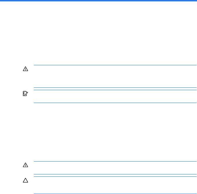
Remove the tower bezel (ML110 G6 servers)
1.Remove the access panel (on page 7).
2.To release the bezel, push the left side of the bezel.
3.Release the tabs, then turn the bezel counter-clockwise to remove it.
To replace the component, reverse the removal procedure.
For server-specific information, see the installation sheet that ships with the server.
Remove the tower bezel (ML150 G6 servers)
1.Insert the key provided with the server and turn clockwise to unlock the bezel.
The key is provided for the service person using model HSTNS-7105 with the HP RPS enablement kit.
2.Open the tower bezel.
3.Lift up the tower bezel and remove it from the chassis.
To replace the component, reverse the removal procedure.
For server-specific information, see the installation sheet that ships with the server.
Operations 8

Setup
Optional installation services
Delivered by experienced, certified engineers, HP Care Pack services help you keep your servers up and running with support packages tailored specifically for HP ProLiant systems. HP Care Packs let you integrate both hardware and software support into a single package. A number of service level options are available to meet your needs.
HP Care Pack Services offer upgraded service levels to expand the standard product warranty with easy-to-buy, easy-to-use support packages that help you make the most of your server investments. Some of the Care Pack services are:
•Hardware support
o 6-hour call-to-repair
o 4-hour 24x7 same day
o 4-hour same business day
•Software support
o Microsoft®
oLinux
•Integrated hardware and software support
oCritical Service
o Proactive 24
o Support Plus
o Support Plus 24
•Startup and implementation services for both hardware and software
For more information on Care Packs, see the HP website (http://www.hp.com/hps/carepack).
Rack planning resources
The rack resource kit ships with all HP branded or Compaq branded 9000, 10000, and H9 series racks. For more information on the content of each resource, see the rack resource kit documentation.
Optimum environment
When installing the server, select a location that meets the environmental standards described in this section.
Space and airflow requirements
Tower server
Setup 9

In a tower configuration, leave at least a 7.6-cm (3.0-in) clearance space at the front and back of the server for proper ventilation.
Rack server
To allow for servicing and adequate airflow, observe the following space and airflow requirements when deciding where to install a rack:
•Leave a minimum clearance of 63.5 cm (25 in) in front of the rack.
•Leave a minimum clearance of 76.2 cm (30 in) behind the rack.
•Leave a minimum clearance of 121.9 cm (48 in) from the back of the rack to the back of another rack or row of racks.
•Leave a minimum clearance of 4.4 cm (1.75 in) from the top of the side panel.
HP servers draw in cool air through the front door and expel warm air through the rear door. Therefore, the front and rear rack doors must be adequately ventilated to allow ambient room air to enter the cabinet, and the rear door must be adequately ventilated to allow the warm air to escape from the cabinet.
CAUTION: To prevent improper cooling and damage to the equipment, do not block the ventilation openings.
When vertical space in the rack is not filled by a server or rack component, the gaps between the components cause changes in airflow through the rack and across the servers. Cover all gaps with blanking panels to maintain proper airflow.
CAUTION: Always use blanking panels to fill empty vertical spaces in the rack. This arrangement ensures proper airflow. Using a rack without blanking panels results in improper cooling that can lead to thermal damage.
The 9000 and 10000 Series Racks provide proper server cooling from flow-through perforations in the front and rear doors that provide 64 percent open area for ventilation.
CAUTION: When using a Compaq branded 7000 series rack, install the high airflow rack door insert (PN 327281-B21 for 42U rack, PN 157847-B21 for 22U rack) to provide proper front-to-back airflow and cooling.
CAUTION: If a third-party rack is used, observe the following additional requirements to ensure adequate airflow and to prevent damage to the equipment:
•Front and rear doors—If the 42U rack includes closing front and rear doors, you must allow 5,350 sq cm (830 sq in) of holes evenly distributed from top to bottom to permit adequate airflow (equivalent to the required 64 percent open area for ventilation).
•Side—The clearance between the installed rack component and the side panels of the rack must be a minimum of 7 cm (2.75 in).
Temperature requirements
To ensure continued safe and reliable equipment operation, install or position the system in a well-ventilated, climate-controlled environment.
The maximum recommended ambient operating temperature (TMRA) for most server products is 35°C (95°F). The temperature in the room where the rack is located must not exceed 35°C (95°F).
Setup 10
CAUTION: To reduce the risk of damage to the equipment when installing third-party options:
•Do not permit optional equipment to impede airflow around the server or to increase the internal rack temperature beyond the maximum allowable limits.
•Do not exceed the manufacturer’s TMRA.
Power requirements
Installation of this equipment must comply with local and regional electrical regulations governing the installation of information technology equipment by licensed electricians. This equipment is designed to operate in installations covered by NFPA 70, 1999 Edition (National Electric Code) and NFPA-75, 1992 (code for Protection of Electronic Computer/Data Processing Equipment). For electrical power ratings on options, refer to the product rating label or the user documentation supplied with that option.
WARNING: To reduce the risk of personal injury, fire, or damage to the equipment, do not overload the AC supply branch circuit that provides power to the rack. Consult the electrical authority having jurisdiction over wiring and installation requirements of your facility.
CAUTION: Protect the server from power fluctuations and temporary interruptions with a regulating uninterruptible power supply (UPS). This device protects the hardware from damage caused by power surges and voltage spikes and keeps the system in operation during a power failure.
When installing more than one server, you may need to use additional power distribution devices to safely provide power to all devices. Observe the following guidelines:
•Balance the server power load between available AC supply branch circuits.
•Do not allow the overall system AC current load to exceed 80 percent of the branch circuit AC current rating.
•Do not use common power outlet strips for this equipment.
•Provide a separate electrical circuit for the server.
Electrical grounding requirements
The server must be grounded properly for proper operation and safety. In the United States, you must install the equipment in accordance with NFPA 70, 1999 Edition (National Electric Code), Article 250, as well as any local and regional building codes. In Canada, you must install the equipment in accordance with Canadian Standards Association, CSA C22.1, Canadian Electrical Code. In all other countries, you must install the equipment in accordance with any regional or national electrical wiring codes, such as the International Electrotechnical Commission (IEC) Code 364, parts 1 through 7. Furthermore, you must be sure that all power distribution devices used in the installation, such as branch wiring and receptacles, are listed or certified grounding-type devices.
Because of the high ground-leakage currents associated with multiple servers connected to the same power source, HP recommends the use of a PDU that is either permanently wired to the building’s branch circuit or includes a nondetachable cord that is wired to an industrial-style plug. NEMA locking-style plugs or those complying with IEC 60309 are considered suitable for this purpose. Using common power outlet strips for the server is not recommended.
Setup 11
Rack warnings
WARNING: To reduce the risk of personal injury or damage to the equipment, be sure that:
•The leveling jacks are extended to the floor.
•The full weight of the rack rests on the leveling jacks.
•The stabilizing feet are attached to the rack if it is a single-rack installation.
•The racks are coupled together in multiple-rack installations.
•Only one component is extended at a time. A rack may become unstable if more than one component is extended for any reason.
WARNING: To reduce the risk of personal injury or equipment damage when unloading a rack:
•At least two people are needed to safely unload the rack from the pallet. An empty 42U rack can weigh as much as 115 kg (253 lb), can stand more than 2.1 m (7 ft) tall, and might become unstable when being moved on its casters.
•Never stand in front of the rack when it is rolling down the ramp from the pallet. Always handle the rack from both sides.
Installing hardware options
Install any hardware options before initializing the server. For options installation information, refer to the option documentation. For server-specific information, refer to "Hardware options installation (on page 13)."
Powering up and configuring the server
To power up the server, press the Power On/Standby button.
For detailed information on configuring the server, see the server installation sheet.
Installing the operating system
To operate properly, the server must have a supported operating system. For the latest information on supported operating systems, refer to the HP website (http://www.hp.com/go/supportos).
To install an operating system on the server, insert the operating system CD into the CD-ROM drive and reboot the server. This process may require you to obtain additional drivers from the Easy Set-up CD shipped with the server, or the CD that shipped with the option. The drivers may have updates that are available on the HP website (http://www.hp.com/support).
Follow the on-screen instructions to begin the installation process.
Registering the server
To register the server, refer to the HP Registration website (http://register.hp.com).
Setup 12
Hardware options installation
Introduction
If more than one option is being installed, read the installation instructions for all the hardware options and identify similar steps to streamline the installation process.
WARNING: To reduce the risk of personal injury from hot surfaces, allow the drives and the internal system components to cool before touching them.
CAUTION: To prevent damage to electrical components, properly ground the server before beginning any installation procedure. Improper grounding can cause electrostatic discharge.
Processor option
The server uses embedded PPMs as DC-to-DC converters to provide the proper power to each processor.
CAUTION: To prevent possible server malfunction, do not mix processors of different speeds or cache sizes. Refer to the label on the processor heatsink for a description of the processor.
CAUTION: To avoid damage to the processor and system board, only authorized personnel should attempt to replace or install the processor in this server.
IMPORTANT: Processor socket 1 must be populated at all times or the server does not function.
To install the component:
1.Power down the server (on page 7).
2.For ML110 G6 Servers, extend the server from the rack.
3.For ML150 G6 Servers, do one of the following:
o Unlock and remove the bezel ("Remove the tower bezel (ML150 G6 servers)" on page 8). o Extend the server from the rack.
4.Remove the access panel (on page 7).
CAUTION: Failure to completely open the processor locking lever prevents the processor from seating during installation, leading to hardware damage.
Hardware options installation 13
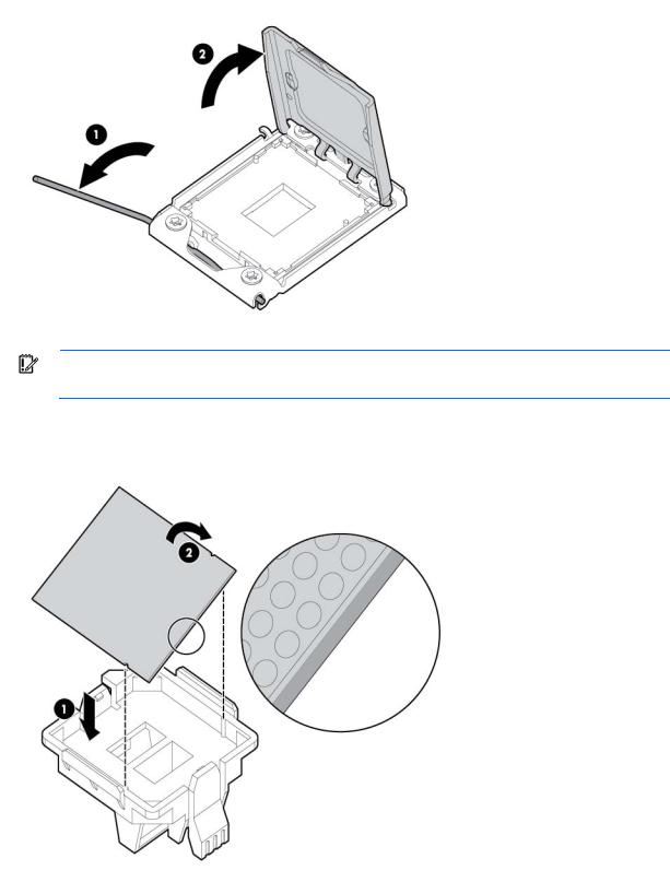
5.Open the processor locking lever and the processor socket retaining bracket. Do not remove the processor socket cover.
IMPORTANT: Be sure the processor remains inside the processor installation tool.
6.If the processor has separated from the installation tool, carefully re-insert the processor in the tool. Handle the processor by the edges only, and do not touch the bottom of the processor, especially the contact area.
Hardware options installation 14
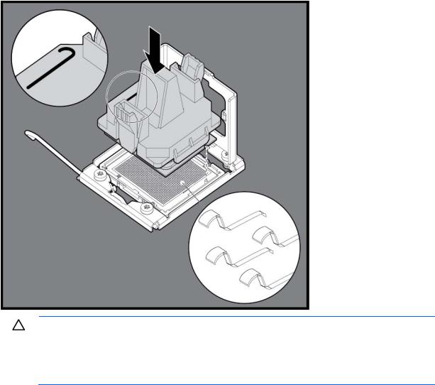
7.Align the processor installation tool with the socket, and then install the processor. THE PINS ON THE SYSTEM BOARD ARE VERY FRAGILE AND EASILY DAMAGED.
CAUTION: THE PINS ON THE SYSTEM BOARD ARE VERY FRAGILE AND EASILY DAMAGED. To avoid damage to the system board:
•Never install or remove a processor without using the processor installation tool.
•Do not touch the processor socket contacts.
•Do not tilt or slide the processor when lowering the processor into the socket.
Hardware options installation 15
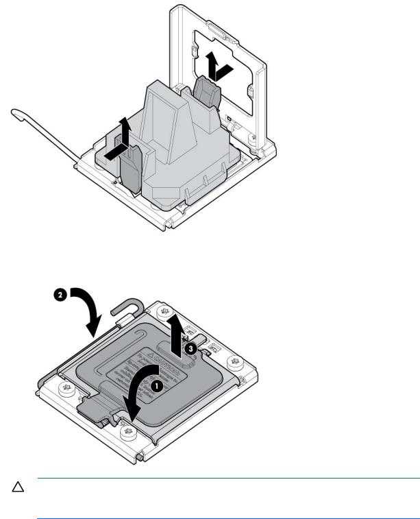
8.Press the tabs on the processor installation tool to separate it from the processor, and then remove the tool.
9.Close the processor socket retaining bracket and the processor locking lever. The processor socket cover is automatically ejected. Remove the cover.
CAUTION: Be sure to close the processor socket retaining bracket before closing the processor locking lever. The lever should close without resistance. Forcing the lever closed can damage the processor and socket, requiring system board replacement.
10.Install the heatsink. See the server installation sheet on the HP website (http://www.hp.com/go/bizsupport).
11.Install the access panel.
12.For ML110 G6 Servers, slide the server back into the rack.
Hardware options installation 16
13.For ML150 G6 Servers, do one of the following: o Close or install the tower bezel, as needed. o Slide the server back into the rack.
14.Power up the server (on page 7).
SAS and SATA_hard drive options
The HP ProLiant ML150 G6 Server supports up to eight hard drives:
•SATA hard drives only with the embedded SATA controller
•SAS or SATA hard drives with an optional SAS controller
For optimal performance, avoid mixing SAS and SATA hard drives.
To install a hard drive, see the server installation sheet on the HP website (http://www.hp.com/go/bizsupport).
For detailed drive cabling information, see the server hood label.
Hard drive LED cable (ML150 G6 servers and ML110 G6 Servers)
An optional hard drive LED cable is required for non-hot-plug hard drive LED functionality with an optional storage controller.
To connect the hard drive LED cable:
1.Power down the server (on page 7).
2.Do one of the following:
o Unlock and remove the bezel ("Remove the tower bezel (ML150 G6 servers)" on page 8). o Extend the server from the rack.
3.Remove the access panel (on page 7).
4.Install the storage controller card.
For more information, see the documentation that ships with the option and see "Expansion board options (on page 26)."
5.Connect the LED cable to the storage controller card.
6.Secure the cable with the cable clamp.
7.Connect the LED cable to the system board.
For more information, see the label attached to the server access panel.
8.Install the access panel.
9.Do one of the following:
o Close or install the tower bezel, as needed. o Slide the server back into the rack.
10.Power up the server (on page 7).
Hardware options installation 17
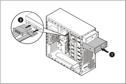
Removable media device option (ML110 G6 servers)
This process only represents one installation method. For instructions for installing the media device into a specific server, see the installation sheet that ships with the server or the HP website (http://www.hp.com/go/bizsupport).
To install the component:
1.Power down the server (on page 7).
2.Extend the server from the rack.
3.Remove the access panel (on page 7).
4.Remove the tower bezel ("Remove the tower bezel (ML110 G6 servers)" on page 8).
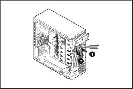
5.Using a Phillips screwdriver, press the release tab on the bezel blank, then remove the shield. HP recommends that you remove all bezel blanks to facilitate drive installation.
6.Install the four screws into the top screw holes on the media device.
7.Slide the media device part into the bay.
Hardware options installation 18
8.Connect the data and power cables.
9.Connect the cables to the system board or to an expansion board, as directed by the option documentation.
10.Slide the server back into the rack.
11.Install the access panel.
12.Install the tower bezel.
13.Power up the server (on page 7).
Removable media device option (ML150 G6 servers)
This process represents only one installation method. For instructions for installing the media device into a specific server, see the installation sheet that ships with the server or the HP website (http://www.hp.com/go/bizsupport).
To install the component:
1.Power down the server (on page 7).
2.Do one of the following:
o Unlock and remove the bezel ("Remove the tower bezel (ML150 G6 servers)" on page 8). o Extend the server from the rack.
3.Remove the access panel (on page 7).
Hardware options installation 19

4.Press the fan holder release tab, and then remove the fan holder.
5.Remove the bezel blank.
HP recommends that you remove all bezel blanks to facilitate drive installation.
6.Slide the media device part of the way into the bay.
7.Connect the SATA power cable to the media drive.
8.Connect the device cable to the device and the system board or to an expansion board, as directed by the option documentation.
9.Slide the media drive fully into the bay until it is seated securely.
10.Install the fan holder.
11.Install the access panel.
12.Do one of the following:
o Close or install the tower bezel, as needed. o Slide the server back into the rack.
Hardware options installation 20
13. Power up the server (on page 7).
Memory options (ML110 G6 servers)
The memory subsystem in this server supports UDIMMs. In this section, the term "DIMM" is used. When specified as UDIMM, the information applies to that type only. All memory installed in the server must be the same type.
The server supports the following DIMM speeds:
•Singleand dual-rank PC3-10600E (DDR-1333) DIMMs operating at 1333 and 1066 MHz
•Singleand dual-rank PC3-8500E (DDR3), DIMMs operating at 1066 MHz
Depending on the processor model, the number of DIMMs installed, the memory clock speed may be reduced to 1066 or 800 MHz. For more information on the effect of DIMM slot population, see "General DIMM slot population guidelines (on page 25)."
Memory subsystem architecture (ML110 G6 Servers)
The memory subsystem in this server is divided into channels. Each processor supports three channels, and each channel supports two DIMM slots, as shown in the following table.
Channel |
Slot |
Slot number |
|
|
|
1 |
C |
1 |
|
A |
2 |
2 |
D |
3 |
|
B |
4 |
This multichannel architecture provides enhanced performance in Advanced ECC mode. The Mirrored Memory and the Lockstep Memory modes are not supported in this architecture. This server supports both RDIMMs and UDIMMs.
DIMM slots in this server are identified by number and by letter. Letters identify the slots to populate for specific AMP modes. Slot numbers are reported by ROM messages during boot and for error reporting.
Singleand dual-rank DIMMs (ML110 G6 servers)
To understand and configure memory protection modes properly, an understanding of single-, dual-, and quad-rank DIMMs is helpful. Some DIMM configuration requirements are based on these classifications.
A single-rank DIMM has one set of memory chips that is accessed while writing to or reading from the memory. A dual-rank DIMM is similar to having two single-rank DIMMs on the same module, with only one rank accessible at a time. A quad-rank DIMM is, effectively, two dual-rank DIMMs on the same module. Only one rank is accessible at a time. The server memory control subsystem selects the proper rank within the DIMM when writing to or reading from the DIMM.
Dual-rank DIMMs provide the greatest capacity with the existing memory technology. For example, if current DRAM technology supports 2-GB single-rank DIMMs, a dual-rank DIMM would be 4-GB.
DIMM identification
Hardware options installation 21
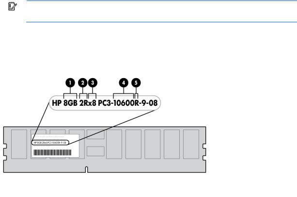
IMPORTANT: This server does not support mixing RDIMMs and UDIMMs. Attempting to mix these two types causes the server to halt during BIOS initialization.
The memory subsystem may be populated with either RDIMMs or UDIMMs, but mixing the two types is not supported. To determine DIMM characteristics, use the label attached to the DIMM and the following illustration and table.
Item |
Description |
Definition |
|
|
|
|
|
1 |
Size |
— |
|
2 |
Rank |
1R |
= Single-rank |
|
|
2R |
= Dual-rank |
|
|
4R |
= Quad-rank |
|
|
|
|
3 |
Data width |
x4 = 4-bit |
|
|
|
x8 = 8-bit |
|
4 |
Memory speed |
10600 = 1333-MHz |
|
|
|
8500 = 1066-MHz |
|
5 |
DIMM type |
R = RDIMM (registered) |
|
|
|
E = UDIMM (unbuffered with ECC) |
|
For the latest supported memory information, see the QuickSpecs on the HP website (http://www.hp.com).
UDIMM maximum memory configurations (ML110 G6 servers)
The server supports a maximum of 8 GB using 2-GB dual-rank UDIMMs.
General DIMM slot population guidelines (ML110 G6 servers)
Observe the following guidelines when populating DIMMs:
•Populate DIMM slots for a processor only if the processor is installed.
•Do not mix Unbuffered and Registered PC3 DIMMs.
•Each channel supports up to two Unbuffered DIMMs.
•Single DIMM (non-interleaving) must be installed in slot 2.
Hardware options installation 22

•Two DIMMs (interleaving) install in slot 2 and slot 4 for optimal performance.
Memory options (ML150 G6 servers)
IMPORTANT: This server does not support mixing RDIMMs and UDIMMs. Attempting to mix these two types causes the server to halt during BIOS initialization.
The memory subsystem in this server can support RDIMMs or UDIMMs. Both types are referred to as DIMMs when the information applies to both types. When specified as RDIMM or UDIMM, the information applies to that type only. All memory installed in the server must be the same type.
The server supports the following DIMM speeds:
•Singleand dual-rank PC3-10600 (DDR-1333) DIMMs operating at 1333 and 1066 MHz
•Quad-rank PC3-8500 (DDR-1067) DIMMs operating at 1066 MHz
Depending on the processor model, the number of DIMMs installed, and whether UDIMMs or RDIMMs are installed, the memory clock speed may be reduced to 1066 or 800 MHz. For more information on the effect of DIMM slot population, see "General DIMM slot population guidelines (on page 25)."
Memory subsystem architecture (ML150 G6 Servers)
The memory subsystem in this server is divided into channels. Each processor supports three channels, and each channel supports two DIMM slots, as shown in the following table.
Channel |
Slot |
Slot number |
|
|
|
1 |
D |
1 |
|
A |
2 |
2 |
E |
3 |
|
B |
4 |
3 |
F |
5 |
|
C |
6 |
This multichannel architecture provides enhanced performance in Advanced ECC mode. The Mirrored Memory and the Lockstep Memory modes are not supported in this architecture. This server supports both RDIMMs and UDIMMs.
DIMM slots in this server are identified by number and by letter. Letters identify the slots to populate for specific AMP modes. Slot numbers are reported by ROM messages during boot and for error reporting.
Single-, dual-, and quad-rank DIMMs
To understand and configure memory protection modes properly, an understanding of single-, dual-, and quad-rank DIMMs is helpful. Some DIMM configuration requirements are based on these classifications.
A single-rank DIMM has one set of memory chips that is accessed while writing to or reading from the memory. A dual-rank DIMM is similar to having two single-rank DIMMs on the same module, with only one rank accessible at a time. A quad-rank DIMM is, effectively, two dual-rank DIMMs on the same module. Only one rank is accessible at a time. The server memory control subsystem selects the proper rank within the DIMM when writing to or reading from the DIMM.
Hardware options installation 23

Dualand quad-rank DIMMs provide the greatest capacity with the existing memory technology. For example, if current DRAM technology supports 2-GB single-rank DIMMs, a dual-rank DIMM would be 4-GB, and a quad-rank DIMM would be 8-GB.
DIMM identification
IMPORTANT: This server does not support mixing RDIMMs and UDIMMs. Attempting to mix these two types causes the server to halt during BIOS initialization.
The memory subsystem may be populated with either RDIMMs or UDIMMs, but mixing the two types is not supported. To determine DIMM characteristics, use the label attached to the DIMM and the following illustration and table.
Item |
Description |
Definition |
|
|
|
|
|
1 |
Size |
— |
|
2 |
Rank |
1R |
= Single-rank |
|
|
2R |
= Dual-rank |
|
|
4R |
= Quad-rank |
|
|
|
|
3 |
Data width |
x4 = 4-bit |
|
|
|
x8 = 8-bit |
|
4 |
Memory speed |
10600 = 1333-MHz |
|
|
|
8500 = 1066-MHz |
|
5 |
DIMM type |
R = RDIMM (registered) |
|
|
|
E = UDIMM (unbuffered with ECC) |
|
For the latest supported memory information, see the QuickSpecs on the HP website (http://www.hp.com).
Memory configurations
To optimize server availability, the server supports Advanced ECC, which provides the greatest memory capacity for a given DIMM size, while providing up to 8-bit error correction, depending on the specific DIMM type. This mode is the default option for this server.
Hardware options installation 24
Advanced Memory Protection options are configured in RBSU. If the requested AMP mode is not supported by the installed DIMM configuration, the server boots in Advanced ECC mode. For more information, see "HP ROM-Based Setup Utility ("ROM-Based Setup Utility" on page 38)."
For the latest memory configuration information, see the QuickSpecs on the HP website (http://www.hp.com).
RDIMM maximum memory configurations
The following table lists the maximum memory configuration possible with 4-GB RDIMMs.
Rank |
Single-processor |
Dual-processor |
|
|
|
Single-rank |
24 GB |
48 GB |
Dual-rank |
24 GB |
48 GB |
Quad-rank |
24 GB |
48 GB |
UDIMM maximum memory configurations
The server supports a maximum of 12 GB with one processor and 24 GB with two processors using 2-GB singleor dual-rank UDIMMs.
Advanced ECC memory configuration
Advanced ECC memory is the default memory protection mode for this server. Standard ECC can correct single-bit memory errors and detect multi-bit memory errors. When multi-bit errors are detected using Standard ECC, the error is signaled to the server and causes the server to halt.
Advanced ECC protects the server against some multi-bit memory errors. Advanced ECC can correct both single-bit memory errors and 4-bit memory errors if all failed bits are on the same DRAM device on the DIMM.
Advanced ECC provides additional protection over Standard ECC because it is possible to correct certain memory errors that would otherwise be uncorrected and result in a server failure. The server provides notification that correctable error events have exceeded a pre-defined threshold rate.
General DIMM slot population guidelines
Observe the following guidelines for all AMP modes:
•Populate DIMM slots for a processor only if the processor is installed.
•To maximize performance in multi-processor configurations, distribute the total memory capacity between all processors as evenly as possible.
•Do not mix Unbuffered and Registered PC3 DIMMs.
•Each channel supports up to two Unbuffered DIMMs.
•If quad-rank DIMMs are installed for a processor, a maximum of two DIMMs can be installed on each channel for that processor.
If a channel contains quad-rank DIMMs, the quad-rank DIMM must be installed first on that channel. DIMM speeds are supported as indicated in the following table.
Hardware options installation 25

Populated slots |
Rank |
Speeds supported |
(per channel) |
|
(MHz) |
|
|
|
1 |
Singleor dual-rank |
800, 1333, 1066 |
1 |
Quad-rank |
800, 1066 |
2 |
Singleor dual-rank |
800, 1066 |
2 |
Single-, dual-, or quad-rank |
800 |
Advanced ECC population guidelines
For Advanced ECC mode configurations, observe the following guidelines:
•Observe the general DIMM slot population guidelines (on page 25).
•DIMMs may be installed individually.
Single-processor Advanced ECC population order
For Advanced ECC mode configurations with a single processor, populate the DIMM slots in the following order:
•RDIMM: Sequentially in alphabetical order (A through F)
•UDIMM: Sequentially in alphabetical order (A through F).
Multi-processor Advanced ECC population order
For Advanced ECC mode configurations with multiple processors, populate the DIMM slots for each processor in the following order:
•RDIMM: Sequentially in alphabetical order (A through F)
•UDIMM: Sequentially in alphabetical order (A through F).
Expansion board options
For server-specific expansion board installation instructions, refer to the installation sheet that ships with the server.
CAUTION: To prevent damage to the server or expansion boards, power down the server and remove all AC power cords before removing or installing the expansion boards.
To install the component:
1.Power down the server (on page 7).
2.For ML110 G6 servers, extend the server from the rack.
3.For ML150 G6 servers, do one of the following:
o Unlock and remove the bezel ("Remove the tower bezel (ML150 G6 servers)" on page 8). o Extend the server from the rack.
4.Remove the access panel (on page 7).
5.Open the slot cover retainer:
Hardware options installation 26
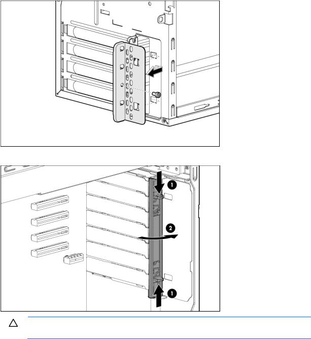
o HP ProLiant ML110 G6 server
o HP ProLiant ML150 G6 server
CAUTION: To prevent improper cooling and thermal damage, do not operate the server unless all PCI slots have either an expansion slot cover or an expansion board installed.
Hardware options installation 27
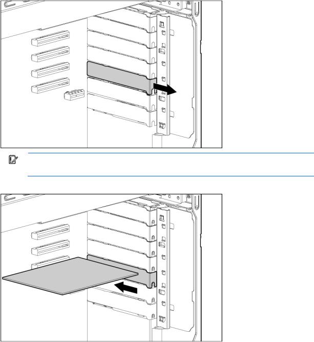
6.Remove the expansion slot cover.
IMPORTANT: It may be necessary to remove the slot cover next to the slot in which you are installing a board.
7.Install the expansion board.
8.Close the slot cover retainer.
9.Connect any required internal cables to the expansion board.
For more information, see the documentation that ships with the expansion board.
10.Install the access panel.
11.For ML110 G6 servers, slide the server back into the rack.
12.For ML150 G6 servers, do one of the following: o Close or install the tower bezel, as needed. o Slide the server back into the rack.
Hardware options installation 28
13.Connect any required external cables to the expansion board.
14.Power up the server (on page 7).
Installing a storage controller
IMPORTANT: For additional installation and configuration information, refer to the documentation that ships with the option.
To install the component:
1.Power down the server (on page 7).
2.For ML110 G6 servers, extend the server from the rack.
3.For ML150 G6 servers, do one of the following:
o Unlock and remove the bezel ("Remove the tower bezel (ML150 G6 servers)" on page 8). o Extend the server from the rack.
4.Remove the server from the rack.
5.Remove the access panel (on page 7).
6.For ML150 G6 servers, remove the PCI riser board assembly. For instructions, see the server installation sheet.
7.For ML150 G6 servers, remove the hard drive cables.
8.Install the storage controller into a full-height/full-length PCIe2 x16 expansion slot ("Expansion board options" on page 26).
For server-specific instructions, see the server installation sheet.
9.Connect the storage controller cable to the controller and to the hard drive.
For server-specific instructions, see the server installation sheet and the documentation that ships with the storage controller.
IMPORTANT: The server does not power up if the PCI riser board assembly is not seated properly.
10.For ML150 G6 servers, install the PCI riser board assembly.
For server-specific instructions, see the server installation sheet and the documentation that ships with the storage controller.
11.Install the access panel.
12.For ML110 G6 servers, slide the server back into the rack
13.For ML150 G6 servers, do one of the following: o Close or install the tower bezel, as needed. o Slide the server back into the rack.
14.Power up the server (on page 7).
Installing DIMMs
CAUTION: To avoid damage to the hard drives, memory, and other system components, the air baffle, drive blanks, and access panel must be installed when the server is powered up.
Hardware options installation 29
1.Power down the server (on page 7).
2.For ML110 G6 servers, extend the server from the rack.
3.For ML150 G6 servers, do one of the following:
o Unlock and remove the bezel ("Remove the tower bezel (ML150 G6 servers)" on page 8). o Extend the server from the rack.
4.Remove the access panel (on page 7).
5.Remove the air baffle.
For more information, see the server installation sheet on the HP website (http://www.hp.com/go/bizsupport).
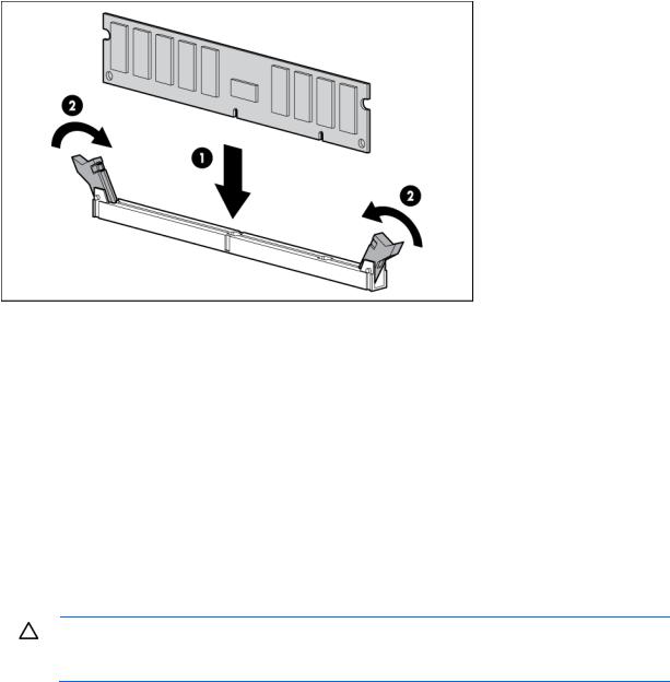
6.Open the DIMM slot latches.
7.Install the DIMM.
8.Install the air baffle.
9.Install the access panel.
10.For ML110 G6 servers, slide the server back into the rack.
11.For ML150 G6 servers, do one of the following: o Close or install the tower bezel, as needed. o Slide the server back into the rack.
If you are installing DIMMs in lock-step configuration, configure this mode in RBSU ("ROM-Based Setup Utility" on page 38).
For more information about LEDs and troubleshooting failed DIMMs, see the server installation sheet on the HP website (http://www.hp.com/go/bizsupport).
Battery-backed write cache battery pack option
CAUTION: To prevent a server malfunction or damage to the equipment, do not add or remove the battery pack while an array capacity expansion, RAID level migration, or stripe size migration is in progress.
Hardware options installation 30
Loading...