


 Loading...
Technical Reference Guide
HP Compaq dc7900 Series
Business Desktop Computers
Document Part Number: 506665-001
September 2008
This document provides information on the design, architecture, function, and capabilities of the HP Compaq dc7900 Series Business Desktop Computers. This information may be used by engineers, technicians, administrators, or anyone needing detailed information on the products covered.
© Copyright 2008 Hewlett-Packard Development Company, L.P. The information contained herein is subject to change without notice.
Microsoft, MS-DOS, Windows, and Windows NT are trademarks of Microsoft Corporation in the U.S. and other countries.
Intel, Intel Core 2 Duo, Intel Core 2 Quad, Pentium Dual-Core, Intel Inside, and Celeron are trademarks of Intel Corporation in the U.S. and other countries.
Adobe, Acrobat, and Acrobat Reader are trademarks or registered trademarks of Adobe Systems Incorporated.
The only warranties for HP products and services are set forth in the express warranty statements accompanying such products and services. Nothing herein should be construed as constituting an additional warranty. HP shall not be liable for technical or editorial errors or omissions contained herein.
This document contains proprietary information that is protected by copyright. No part of this document may be photocopied, reproduced, or translated to another language without the prior written consent of Hewlett-Packard Company.
Technical Reference Guide
HP Compaq dc7900 Series Business Desktop Computers
First Edition (September 2008)
Document Part Number: 506665-001

Contents
1 Introduction
1.1 About this Guide . . . . . . . . . . . . . . . . . . . . . . . . . . . . . . . . . . . . . . . . . . . . . . . . . . . . . . . . . . . . . 1–1 1.1.1 Online Viewing . . . . . . . . . . . . . . . . . . . . . . . . . . . . . . . . . . . . . . . . . . . . . . . . . . . . . . . . . 1–1 1.1.2 Hardcopy . . . . . . . . . . . . . . . . . . . . . . . . . . . . . . . . . . . . . . . . . . . . . . . . . . . . . . . . . . . . . . 1–1 1.2 Additional Information Sources . . . . . . . . . . . . . . . . . . . . . . . . . . . . . . . . . . . . . . . . . . . . . . . . . 1–1 1.3 Model Numbering Convention . . . . . . . . . . . . . . . . . . . . . . . . . . . . . . . . . . . . . . . . . . . . . . . . . . 1–1 1.4 Serial Number . . . . . . . . . . . . . . . . . . . . . . . . . . . . . . . . . . . . . . . . . . . . . . . . . . . . . . . . . . . . . . . 1–3 1.5 Notational Conventions . . . . . . . . . . . . . . . . . . . . . . . . . . . . . . . . . . . . . . . . . . . . . . . . . . . . . . . . 1–3 1.5.1 Special Notices . . . . . . . . . . . . . . . . . . . . . . . . . . . . . . . . . . . . . . . . . . . . . . . . . . . . . . . . . . 1–3 1.5.2 Values. . . . . . . . . . . . . . . . . . . . . . . . . . . . . . . . . . . . . . . . . . . . . . . . . . . . . . . . . . . . . . . . . 1–3 1.5.2 Ranges . . . . . . . . . . . . . . . . . . . . . . . . . . . . . . . . . . . . . . . . . . . . . . . . . . . . . . . . . . . . . . . . 1–3 1.6 Common Acronyms and Abbreviations . . . . . . . . . . . . . . . . . . . . . . . . . . . . . . . . . . . . . . . . . . . 1–4
2 System Overview
2.1 Introduction . . . . . . . . . . . . . . . . . . . . . . . . . . . . . . . . . . . . . . . . . . . . . . . . . . . . . . . . . . . . . . . . . 2–1
2.2 Features . . . . . . . . . . . . . . . . . . . . . . . . . . . . . . . . . . . . . . . . . . . . . . . . . . . . . . . . . . . . . . . . . . . . 2–2
2.3 System Architecture . . . . . . . . . . . . . . . . . . . . . . . . . . . . . . . . . . . . . . . . . . . . . . . . . . . . . . . . . . 2–4
2.3.1 Intel Processor Support . . . . . . . . . . . . . . . . . . . . . . . . . . . . . . . . . . . . . . . . . . . . . . . . . . . 2–6
2.3.2 Chipset . . . . . . . . . . . . . . . . . . . . . . . . . . . . . . . . . . . . . . . . . . . . . . . . . . . . . . . . . . . . . . . . 2–7
2.3.3 Support Components . . . . . . . . . . . . . . . . . . . . . . . . . . . . . . . . . . . . . . . . . . . . . . . . . . . . . 2–8
2.3.4 System Memory . . . . . . . . . . . . . . . . . . . . . . . . . . . . . . . . . . . . . . . . . . . . . . . . . . . . . . . . . 2–8
2.3.5 Mass Storage . . . . . . . . . . . . . . . . . . . . . . . . . . . . . . . . . . . . . . . . . . . . . . . . . . . . . . . . . . . 2–9
2.3.6 Serial Interface . . . . . . . . . . . . . . . . . . . . . . . . . . . . . . . . . . . . . . . . . . . . . . . . . . . . . . . . . . 2–9
2.3.7 Universal Serial Bus Interface . . . . . . . . . . . . . . . . . . . . . . . . . . . . . . . . . . . . . . . . . . . . . . 2–9
2.3.8 Network Interface Controller . . . . . . . . . . . . . . . . . . . . . . . . . . . . . . . . . . . . . . . . . . . . . . . 2–9
2.3.9 Graphics Subsystem . . . . . . . . . . . . . . . . . . . . . . . . . . . . . . . . . . . . . . . . . . . . . . . . . . . . . 2–10
2.3.10 Audio Subsystem . . . . . . . . . . . . . . . . . . . . . . . . . . . . . . . . . . . . . . . . . . . . . . . . . . . . . . 2–10
2.4 Specifications. . . . . . . . . . . . . . . . . . . . . . . . . . . . . . . . . . . . . . . . . . . . . . . . . . . . . . . . . . . . . . . 2–11
|
Technical Reference Guide |
www.hp.com |
iii |

Contents
3 Processor/Memory Subsystem
3.1 Introduction . . . . . . . . . . . . . . . . . . . . . . . . . . . . . . . . . . . . . . . . . . . . . . . . . . . . . . . . . . . . . . . . . 3–1
3.2 Intel Processors . . . . . . . . . . . . . . . . . . . . . . . . . . . . . . . . . . . . . . . . . . . . . . . . . . . . . . . . . . . . . . 3–2
3.2.1 Intel Processor Overview . . . . . . . . . . . . . . . . . . . . . . . . . . . . . . . . . . . . . . . . . . . . . . . . . . 3–2
3.2.2 Processor Changing/Upgrading . . . . . . . . . . . . . . . . . . . . . . . . . . . . . . . . . . . . . . . . . . . . . 3–3
3.3 Memory Subsystem . . . . . . . . . . . . . . . . . . . . . . . . . . . . . . . . . . . . . . . . . . . . . . . . . . . . . . . . . . . 3–4
3.3.1 Memory Upgrading . . . . . . . . . . . . . . . . . . . . . . . . . . . . . . . . . . . . . . . . . . . . . . . . . . . . . . 3–5
3.3.2 Memory Mapping and Pre-allocation . . . . . . . . . . . . . . . . . . . . . . . . . . . . . . . . . . . . . . . . 3–5
4 System Support
4.1 Introduction . . . . . . . . . . . . . . . . . . . . . . . . . . . . . . . . . . . . . . . . . . . . . . . . . . . . . . . . . . . . . . . . . 4–1
4.2 PCI Bus Overview. . . . . . . . . . . . . . . . . . . . . . . . . . . . . . . . . . . . . . . . . . . . . . . . . . . . . . . . . . . . 4–1
4.2.1 PCI 2.3 Bus Operation . . . . . . . . . . . . . . . . . . . . . . . . . . . . . . . . . . . . . . . . . . . . . . . . . . . . 4–1
4.2.2 PCI Express Bus Operation . . . . . . . . . . . . . . . . . . . . . . . . . . . . . . . . . . . . . . . . . . . . . . . . 4–3
4.2.3 Option ROM Mapping . . . . . . . . . . . . . . . . . . . . . . . . . . . . . . . . . . . . . . . . . . . . . . . . . . . . 4–4
4.2.4 PCI Interrupts . . . . . . . . . . . . . . . . . . . . . . . . . . . . . . . . . . . . . . . . . . . . . . . . . . . . . . . . . . . 4–4
4.2.5 PCI Power Management Support . . . . . . . . . . . . . . . . . . . . . . . . . . . . . . . . . . . . . . . . . . . . 4–4
4.2.6 PCI Connectors. . . . . . . . . . . . . . . . . . . . . . . . . . . . . . . . . . . . . . . . . . . . . . . . . . . . . . . . . . 4–5
4.3 System Resources . . . . . . . . . . . . . . . . . . . . . . . . . . . . . . . . . . . . . . . . . . . . . . . . . . . . . . . . . . . . 4–7
4.3.1 Interrupts . . . . . . . . . . . . . . . . . . . . . . . . . . . . . . . . . . . . . . . . . . . . . . . . . . . . . . . . . . . . . . 4–7
4.3.2 Direct Memory Access. . . . . . . . . . . . . . . . . . . . . . . . . . . . . . . . . . . . . . . . . . . . . . . . . . . . 4–8
4.4 Real-Time Clock and Configuration Memory. . . . . . . . . . . . . . . . . . . . . . . . . . . . . . . . . . . . . . . 4–9
4.4.1 Clearing CMOS . . . . . . . . . . . . . . . . . . . . . . . . . . . . . . . . . . . . . . . . . . . . . . . . . . . . . . . . . 4–9
4.4.2 Standard CMOS Locations. . . . . . . . . . . . . . . . . . . . . . . . . . . . . . . . . . . . . . . . . . . . . . . . 4–10
4.5 System Management . . . . . . . . . . . . . . . . . . . . . . . . . . . . . . . . . . . . . . . . . . . . . . . . . . . . . . . . . 4–10
4.5.1 Security Functions . . . . . . . . . . . . . . . . . . . . . . . . . . . . . . . . . . . . . . . . . . . . . . . . . . . . . . 4–10
4.5.2 Power Management . . . . . . . . . . . . . . . . . . . . . . . . . . . . . . . . . . . . . . . . . . . . . . . . . . . . . 4–12
4.5.3 System Status . . . . . . . . . . . . . . . . . . . . . . . . . . . . . . . . . . . . . . . . . . . . . . . . . . . . . . . . . . 4–12
4.5.4 Thermal Sensing and Cooling . . . . . . . . . . . . . . . . . . . . . . . . . . . . . . . . . . . . . . . . . . . . . 4–13
4.6 Register Map and Miscellaneous Functions . . . . . . . . . . . . . . . . . . . . . . . . . . . . . . . . . . . . . . . 4–14
4.6.1 System I/O Map . . . . . . . . . . . . . . . . . . . . . . . . . . . . . . . . . . . . . . . . . . . . . . . . . . . . . . . . 4–14
4.6.2 GPIO Functions . . . . . . . . . . . . . . . . . . . . . . . . . . . . . . . . . . . . . . . . . . . . . . . . . . . . . . . . 4–16
5 Input/Output Interfaces
5.1 Introduction . . . . . . . . . . . . . . . . . . . . . . . . . . . . . . . . . . . . . . . . . . . . . . . . . . . . . . . . . . . . . . . . . 5–1
5.2 SATA/eSATA Interface . . . . . . . . . . . . . . . . . . . . . . . . . . . . . . . . . . . . . . . . . . . . . . . . . . . . . . . 5–2
5.5.1 SATA Inteerface. . . . . . . . . . . . . . . . . . . . . . . . . . . . . . . . . . . . . . . . . . . . . . . . . . . . . . . . . 5–2
5.5.2 eSATA Interface. . . . . . . . . . . . . . . . . . . . . . . . . . . . . . . . . . . . . . . . . . . . . . . . . . . . . . . . . 5–3
5.3 Diskette Drive Interface. . . . . . . . . . . . . . . . . . . . . . . . . . . . . . . . . . . . . . . . . . . . . . . . . . . . . . . . 5–4
5.4 Serial Interface. . . . . . . . . . . . . . . . . . . . . . . . . . . . . . . . . . . . . . . . . . . . . . . . . . . . . . . . . . . . . . . 5–6
5.5 Parallel Interface Support . . . . . . . . . . . . . . . . . . . . . . . . . . . . . . . . . . . . . . . . . . . . . . . . . . . . . . 5–7
5.5.1 Standard Parallel Port Mode. . . . . . . . . . . . . . . . . . . . . . . . . . . . . . . . . . . . . . . . . . . . . . . . 5–7
5.5.2 Enhanced Parallel Port Mode . . . . . . . . . . . . . . . . . . . . . . . . . . . . . . . . . . . . . . . . . . . . . . . 5–7
5.5.3 Extended Capabilities Port Mode. . . . . . . . . . . . . . . . . . . . . . . . . . . . . . . . . . . . . . . . . . . . 5–7
5.5.4 Parallel Interface Connector. . . . . . . . . . . . . . . . . . . . . . . . . . . . . . . . . . . . . . . . . . . . . . . . 5–8
5.6 Keyboard/Pointing Device Interface . . . . . . . . . . . . . . . . . . . . . . . . . . . . . . . . . . . . . . . . . . . . . . 5–9
5.6.1 Keyboard Interface Operation . . . . . . . . . . . . . . . . . . . . . . . . . . . . . . . . . . . . . . . . . . . . . . 5–9
|
iv |
www.hp.com |
Technical Reference Guide |

Contents
5.6.2 Pointing Device Interface Operation . . . . . . . . . . . . . . . . . . . . . . . . . . . . . . . . . . . . . . . . 5–10
5.6.3 Keyboard/Pointing Device Interface Connector . . . . . . . . . . . . . . . . . . . . . . . . . . . . . . . 5–10
5.7 Universal Serial Bus Interface. . . . . . . . . . . . . . . . . . . . . . . . . . . . . . . . . . . . . . . . . . . . . . . . . . 5–11
5.7.1 USB Connector. . . . . . . . . . . . . . . . . . . . . . . . . . . . . . . . . . . . . . . . . . . . . . . . . . . . . . . . . 5–11
5.7.2 USB Cable Data . . . . . . . . . . . . . . . . . . . . . . . . . . . . . . . . . . . . . . . . . . . . . . . . . . . . . . . . 5–12
5.8 Audio Subsystem. . . . . . . . . . . . . . . . . . . . . . . . . . . . . . . . . . . . . . . . . . . . . . . . . . . . . . . . . . . . 5–13
5.8.1 HD Audio Controller . . . . . . . . . . . . . . . . . . . . . . . . . . . . . . . . . . . . . . . . . . . . . . . . . . . . 5–14
5.8.2 HD Audio Link Bus . . . . . . . . . . . . . . . . . . . . . . . . . . . . . . . . . . . . . . . . . . . . . . . . . . . . . 5–14
5.8.3 Audio Multistreaming . . . . . . . . . . . . . . . . . . . . . . . . . . . . . . . . . . . . . . . . . . . . . . . . . . . 5–14
5.8.4 Audio Specifications . . . . . . . . . . . . . . . . . . . . . . . . . . . . . . . . . . . . . . . . . . . . . . . . . . . . 5–15
5.9 Network Interface Controller. . . . . . . . . . . . . . . . . . . . . . . . . . . . . . . . . . . . . . . . . . . . . . . . . . . 5–16
5.9.1 Wake-On-LAN Support . . . . . . . . . . . . . . . . . . . . . . . . . . . . . . . . . . . . . . . . . . . . . . . . . 5–17
5.9.2 Alert Standard Format Support . . . . . . . . . . . . . . . . . . . . . . . . . . . . . . . . . . . . . . . . . . . . 5–17
5.9.3 Power Management Support . . . . . . . . . . . . . . . . . . . . . . . . . . . . . . . . . . . . . . . . . . . . . . 5–17
5.9.4 NIC Connector . . . . . . . . . . . . . . . . . . . . . . . . . . . . . . . . . . . . . . . . . . . . . . . . . . . . . . . . 5–18
5.9.5 NIC Specifications . . . . . . . . . . . . . . . . . . . . . . . . . . . . . . . . . . . . . . . . . . . . . . . . . . . . . . 5–18
6 Integrated Graphics Subsystem
6.1 Introduction . . . . . . . . . . . . . . . . . . . . . . . . . . . . . . . . . . . . . . . . . . . . . . . . . . . . . . . . . . . . . . . . . 6–1
6.2 Functional Description . . . . . . . . . . . . . . . . . . . . . . . . . . . . . . . . . . . . . . . . . . . . . . . . . . . . . . . . 6–2
6.3 Display Modes. . . . . . . . . . . . . . . . . . . . . . . . . . . . . . . . . . . . . . . . . . . . . . . . . . . . . . . . . . . . . . . 6–4
6.4 Upgrading . . . . . . . . . . . . . . . . . . . . . . . . . . . . . . . . . . . . . . . . . . . . . . . . . . . . . . . . . . . . . . . . . . 6–5
6.5 Monitor Connectors. . . . . . . . . . . . . . . . . . . . . . . . . . . . . . . . . . . . . . . . . . . . . . . . . . . . . . . . . . . 6–6
6.5.1 Analog Monitor Connector . . . . . . . . . . . . . . . . . . . . . . . . . . . . . . . . . . . . . . . . . . . . . . . . 6–6
6.5.2 DisplayPort Connector . . . . . . . . . . . . . . . . . . . . . . . . . . . . . . . . . . . . . . . . . . . . . . . . . . . . 6–7
7 Power and Signal Distribution
7.1 Introduction . . . . . . . . . . . . . . . . . . . . . . . . . . . . . . . . . . . . . . . . . . . . . . . . . . . . . . . . . . . . . . . . . 7–1
7.2 Power Distribution. . . . . . . . . . . . . . . . . . . . . . . . . . . . . . . . . . . . . . . . . . . . . . . . . . . . . . . . . . . . 7–1
7.2.1 USDT Power Distribution . . . . . . . . . . . . . . . . . . . . . . . . . . . . . . . . . . . . . . . . . . . . . . . . . 7–1
7.2.2 SFF/CMT Power Distribution . . . . . . . . . . . . . . . . . . . . . . . . . . . . . . . . . . . . . . . . . . . . . . 7–2
7.2.3 Energy Star Compliancy . . . . . . . . . . . . . . . . . . . . . . . . . . . . . . . . . . . . . . . . . . . . . . . . . . 7–6
7.3 Power Control . . . . . . . . . . . . . . . . . . . . . . . . . . . . . . . . . . . . . . . . . . . . . . . . . . . . . . . . . . . . . . . 7–6
7.3.1 Power Button . . . . . . . . . . . . . . . . . . . . . . . . . . . . . . . . . . . . . . . . . . . . . . . . . . . . . . . . . . . 7–6
7.3.2 Wake Up Events. . . . . . . . . . . . . . . . . . . . . . . . . . . . . . . . . . . . . . . . . . . . . . . . . . . . . . . . . 7–8
7.3.3 Power Management . . . . . . . . . . . . . . . . . . . . . . . . . . . . . . . . . . . . . . . . . . . . . . . . . . . . . . 7–9
7.4 Signal Distribution. . . . . . . . . . . . . . . . . . . . . . . . . . . . . . . . . . . . . . . . . . . . . . . . . . . . . . . . . . . 7–10
|
Technical Reference Guide |
www.hp.com |
v |

Contents
8 SYSTEM BIOS
8.1 Introduction . . . . . . . . . . . . . . . . . . . . . . . . . . . . . . . . . . . . . . . . . . . . . . . . . . . . . . . . . . . . . . . . . 8–1 8.2 ROM Flashing . . . . . . . . . . . . . . . . . . . . . . . . . . . . . . . . . . . . . . . . . . . . . . . . . . . . . . . . . . . . . . . 8–2 8.2.1 Upgrading. . . . . . . . . . . . . . . . . . . . . . . . . . . . . . . . . . . . . . . . . . . . . . . . . . . . . . . . . . . . . . 8–2 8.2.2 Changeable Splash Screen . . . . . . . . . . . . . . . . . . . . . . . . . . . . . . . . . . . . . . . . . . . . . . . . . 8–2 8.3 Boot Functions. . . . . . . . . . . . . . . . . . . . . . . . . . . . . . . . . . . . . . . . . . . . . . . . . . . . . . . . . . . . . . . 8–3 8.3.1 Boot Device Order . . . . . . . . . . . . . . . . . . . . . . . . . . . . . . . . . . . . . . . . . . . . . . . . . . . . . . . 8–3 8.3.2 Network Boot (F12) Support . . . . . . . . . . . . . . . . . . . . . . . . . . . . . . . . . . . . . . . . . . . . . . . 8–3 8.3.3 Memory Detection and Configuration . . . . . . . . . . . . . . . . . . . . . . . . . . . . . . . . . . . . . . . . 8–3 8.3.4 Boot Error Codes . . . . . . . . . . . . . . . . . . . . . . . . . . . . . . . . . . . . . . . . . . . . . . . . . . . . . . . . 8–4 8.4 Client Management Functions. . . . . . . . . . . . . . . . . . . . . . . . . . . . . . . . . . . . . . . . . . . . . . . . . . . 8–5 8.4.1 System ID and ROM Type. . . . . . . . . . . . . . . . . . . . . . . . . . . . . . . . . . . . . . . . . . . . . . . . . 8–6 8.4.2 Temperature Status. . . . . . . . . . . . . . . . . . . . . . . . . . . . . . . . . . . . . . . . . . . . . . . . . . . . . . . 8–6 8.5 SMBIOS support . . . . . . . . . . . . . . . . . . . . . . . . . . . . . . . . . . . . . . . . . . . . . . . . . . . . . . . . . . . . . 8–7 8.6 USB Legacy Support. . . . . . . . . . . . . . . . . . . . . . . . . . . . . . . . . . . . . . . . . . . . . . . . . . . . . . . . . . 8–8 8.7 Management Engine Functions . . . . . . . . . . . . . . . . . . . . . . . . . . . . . . . . . . . . . . . . . . . . . . . . . . 8–8
A Error Messages and Codes
Index
|
vi |
www.hp.com |
Technical Reference Guide |

1
Introduction
1.1About this Guide
This guide provides technical information about HP Compaq dc7900 Business PC personal computers that feature Intel processors and the Intel Q45 Express chipset. This document describes in detail the system's design and operation for programmers, engineers, technicians, and system administrators, as well as end-users wanting detailed information.
The chapters of this guide primarily describe the hardware and firmware elements and primarily deal with the system board and the power supply assembly. The appendices contain general data such as error codes and information about standard peripheral devices such as keyboards, graphics cards, and communications adapters.
This guide can be used either as an online document or in hardcopy form.
1.1.1 Online Viewing
Online viewing allows for quick navigating and convenient searching through the document. A color monitor will also allow the user to view the color shading used to highlight differential
data. A softcopy of the latest edition of this guide is available for downloading in .pdf file format at the following URL: www.hp.com
Viewing the file requires a copy of Adobe Acrobat Reader available at no charge from Adobe Systems, Inc. at the following URL: www.adobe.com
1.1.2 Hardcopy
A hardcopy of this guide may be obtained by printing from the .pdf file. The document is designed for printing in an 8 ½ x 11-inch format.
1.2Additional Information Sources
For more information on components mentioned in this guide refer to the indicated manufacturers' documentation, which may be available at the following online sources:
■HP Corporation: www.hp.com
■Intel Corporation: www.intel.com
■Serial ATA International Organization (SATA-IO): www.serialATA.org.
■USB user group: www.usb.org
|
Technical Reference Guide |
www.hp.com |
1-1 |

Introduction
1.3Serial Number
The serial number is located on a sticker placed on the exterior cabinet. The serial number is also written into firmware and may be read with HP Diagnostics or Insight Manager utilities.
1.4Notational Conventions
The notational guidelines used in this guide are described in the following subsections.
1.4.1 Special Notices
The usage of warnings, cautions, and notes is described as follows:
ïWARNING:harm or loss ofTextlife.set off in this manner indicates that failure to follow directions could result in bodily
ïCAUTION: Text set off in this manner indicates that failure to follow directions could result in damage to equipment or loss of information.
Text set off in this manner provides information that may be helpful.
1.4.2Values
Differences between bytes and bits are indicated as follows:
MB = megabytes
Mb = megabits
1.4.3 Ranges
Ranges or limits for a parameter are shown using the following methods:
Example A: Bits <7..4> = bits 7, 6, 5, and 4.
Example B: IRQ3-7, 9 = IRQ signals 3 through 7, and IRQ signal 9
|
1-2 |
www.hp.com |
Technical Reference Guide |

Introduction
1.5Common Acronyms and Abbreviations
Table 1-1 lists the acronyms and abbreviations used in this guide.
|
Table 1-1 |
|
Acronyms and Abbreviations |
|
|
Acronym or |
|
Abbreviation |
Description |
|
|
A |
ampere |
|
|
AC |
alternating current |
|
|
ACPI |
Advanced Configuration and Power Interface |
|
|
A/D |
analog-to-digital |
|
|
ADC |
Analog-to-digital converter |
|
|
ADD or ADD2 |
Advanced digital display (card) |
|
|
AGP |
Accelerated graphics port |
|
|
AHCI |
SATA Advanced Host controller Interface |
|
|
AMT |
Active Management Technology |
|
|
API |
application programming interface |
|
|
APIC |
Advanced Programmable Interrupt Controller |
|
|
APM |
advanced power management |
|
|
AOL |
Alert-On-LAN™ |
|
|
ASIC |
application-specific integrated circuit |
|
|
ASF |
Alert Standard Format |
|
|
AT |
1. attention (modem commands) 2. 286-based PC architecture |
|
|
ATA |
AT attachment (IDE protocol) |
|
|
ATAPI |
ATA w/packet interface extensions |
|
|
AVI |
audio-video interleaved |
|
|
AVGA |
Advanced VGA |
|
|
AWG |
American Wire Gauge (specification) |
|
|
BAT |
Basic assurance test |
|
|
BCD |
binary-coded decimal |
|
|
BIOS |
basic input/output system |
|
|
bis |
second/new revision |
|
|
BNC |
Bayonet Neill-Concelman (connector type) |
|
|
bps or b/s |
bits per second |
|
|
BSP |
Bootstrap processor |
|
|
BTO |
Built to order |
|
|
CAS |
column address strobe |
|
|
CD |
compact disk |
|
|
CD-ROM |
compact disk read-only memory |
|
|
|
Technical Reference Guide |
www.hp.com |
1-3 |

Introduction
|
Table 1-1 (Continued) |
|
Acronyms and Abbreviations |
|
|
Acronym or |
|
Abbreviation |
Description |
|
|
CDS |
compact disk system |
|
|
CGA |
color graphics adapter |
|
|
Ch |
Channel, chapter |
|
|
cm |
centimeter |
|
|
CMC |
cache/memory controller |
|
|
CMOS |
complimentary metal-oxide semiconductor (configuration memory) |
|
|
Cntlr |
controller |
|
|
Cntrl |
control |
|
|
codec |
1. coder/decoder 2. compressor/decompressor |
|
|
CPQ |
Compaq |
|
|
CPU |
central processing unit |
|
|
CRIMM |
Continuity (blank) RIMM |
|
|
CRT |
cathode ray tube |
|
|
CSM |
1. Compaq system management 2. Compaq server management |
|
|
DAC |
digital-to-analog converter |
|
|
DC |
direct current |
|
|
DCH |
DOS compatibility hole |
|
|
DDC |
Display Data Channel |
|
|
DDR |
Double data rate (memory) |
|
|
DIMM |
dual inline memory module |
|
|
DIN |
Deutche IndustriNorm (connector type) |
|
|
DIP |
dual inline package |
|
|
DMA |
direct memory access |
|
|
DMI |
Desktop management interface |
|
|
dpi |
dots per inch |
|
|
DRAM |
dynamic random access memory |
|
|
DRQ |
data request |
|
|
DVI |
Digital video interface |
|
|
dword |
Double word (32 bits) |
|
|
EDID |
extended display identification data |
|
|
EDO |
extended data out (RAM type) |
|
|
EEPROM |
electrically erasable PROM |
|
|
EGA |
enhanced graphics adapter |
|
|
EIA |
Electronic Industry Association |
|
|
|
1-4 |
www.hp.com |
Technical Reference Guide |
Introduction
|
Table 1-1 (Continued) |
|
Acronyms and Abbreviations |
|
|
Acronym or |
|
Abbreviation |
Description |
|
|
EISA |
extended ISA |
|
|
EPP |
enhanced parallel port |
|
|
EIDE |
enhanced IDE |
|
|
ESCD |
Extended System Configuration Data (format) |
|
|
EV |
Environmental Variable (data) |
|
|
ExCA |
Exchangeable Card Architecture |
|
|
FIFO |
first in/first out |
|
|
FL |
flag (register) |
|
|
FM |
frequency modulation |
|
|
FPM |
fast page mode (RAM type) |
|
|
FPU |
Floating point unit (numeric or math coprocessor) |
|
|
FPS |
Frames per second |
|
|
ft |
Foot/feet |
|
|
GB |
gigabyte |
|
|
GMCH |
Graphics/memory controller hub |
|
|
GND |
ground |
|
|
GPIO |
general purpose I/O |
|
|
GPOC |
general purpose open-collector |
|
|
GART |
Graphics address re-mapping table |
|
|
GUI |
graphic user interface |
|
|
h |
hexadecimal |
|
|
HDD |
hard disk drive |
|
|
HW |
hardware |
|
|
hex |
hexadecimal |
|
|
Hz |
Hertz (cycles-per-second) |
|
|
ICH |
I/O controller hub |
|
|
IDE |
integrated drive element |
|
|
IEEE |
Institute of Electrical and Electronic Engineers |
|
|
IF |
interrupt flag |
|
|
I/F |
interface |
|
|
IGC |
integrated graphics controller |
|
|
in |
inch |
|
|
INT |
interrupt |
|
|
I/O |
input/output |
|
|
IPL |
initial program loader |
|
|
|
Technical Reference Guide |
www.hp.com |
1-5 |

Introduction
|
Table 1-1 (Continued) |
|
Acronyms and Abbreviations |
|
|
Acronym or |
|
Abbreviation |
Description |
|
|
IrDA |
Infrared Data Association |
|
|
IRQ |
interrupt request |
|
|
ISA |
industry standard architecture |
|
|
Kb/KB |
kilobits/kilobytes (x 1024 bits/x 1024 bytes) |
|
|
Kb/s |
kilobits per second |
|
|
kg |
kilogram |
|
|
KHz |
kilohertz |
|
|
kV |
kilovolt |
|
|
lb |
pound |
|
|
LAN |
local area network |
|
|
LCD |
liquid crystal display |
|
|
LED |
light-emitting diode |
|
|
LPC |
Low pin count |
|
|
LSI |
large scale integration |
|
|
LSb/LSB |
least significant bit/least significant byte |
|
|
LUN |
logical unit (SCSI) |
|
|
m |
Meter |
|
|
MCH |
Memory controller hub |
|
|
MMX |
multimedia extensions |
|
|
MPEG |
Motion Picture Experts Group |
|
|
ms |
millisecond |
|
|
MSb/MSB |
most significant bit/most significant byte |
|
|
mux |
multiplex |
|
|
MVA |
motion video acceleration |
|
|
MVW |
motion video window |
|
|
n |
variable parameter/value |
|
|
NIC |
network interface card/controller |
|
|
NiMH |
nickel-metal hydride |
|
|
NMI |
non-maskable interrupt |
|
|
NRZI |
Non-return-to-zero inverted |
|
|
ns |
nanosecond |
|
|
NT |
nested task flag |
|
|
NTSC |
National Television Standards Committee |
|
|
NVRAM |
non-volatile random access memory |
|
|
|
1-6 |
www.hp.com |
Technical Reference Guide |

Introduction
|
Table 1-1 (Continued) |
|
Acronyms and Abbreviations |
|
|
Acronym or |
|
Abbreviation |
Description |
|
|
ODD |
optical disk drive |
|
|
OS |
operating system |
|
|
PAL |
1. programmable array logic 2. phase alternating line |
|
|
PATA |
Parallel ATA |
|
|
PC |
Personal computer |
|
|
PCA |
Printed circuit assembly |
|
|
PCI |
peripheral component interconnect |
|
|
PCI-E |
PCI Express |
|
|
PCM |
pulse code modulation |
|
|
PCMCIA |
Personal Computer Memory Card International Association |
|
|
PEG |
PCI express graphics |
|
|
PFC |
Power factor correction |
|
|
PIN |
personal identification number |
|
|
PIO |
Programmed I/O |
|
|
PN |
Part number |
|
|
POST |
power-on self test |
|
|
PROM |
programmable read-only memory |
|
|
PTR |
pointer |
|
|
RAID |
Redundant array of inexpensive disks (drives) |
|
|
RAM |
random access memory |
|
|
RAS |
row address strobe |
|
|
rcvr |
receiver |
|
|
RDRAM |
(Direct) Rambus DRAM |
|
|
RGB |
red/green/blue (monitor input) |
|
|
RH |
Relative humidity |
|
|
RMS |
root mean square |
|
|
ROM |
read-only memory |
|
|
RPM |
revolutions per minute |
|
|
RTC |
real time clock |
|
|
R/W |
Read/Write |
|
|
SATA |
Serial ATA |
|
|
SCSI |
small computer system interface |
|
|
SDR |
Singles data rate (memory) |
|
|
SDRAM |
Synchronous Dynamic RAM |
|
|
|
Technical Reference Guide |
www.hp.com |
1-7 |

Introduction
|
Table 1-1 (Continued) |
|
Acronyms and Abbreviations |
|
|
Acronym or |
|
Abbreviation |
Description |
|
|
SDVO |
Serial digital video output |
|
|
SEC |
Single Edge-Connector |
|
|
SECAM |
sequential colour avec memoire (sequential color with memory) |
|
|
SF |
sign flag |
|
|
SGRAM |
Synchronous Graphics RAM |
|
|
SIMD |
Single instruction multiple data |
|
|
SIMM |
single in-line memory module |
|
|
SMART |
Self Monitor Analysis Report Technology |
|
|
SMI |
system management interrupt |
|
|
SMM |
system management mode |
|
|
SMRAM |
system management RAM |
|
|
SPD |
serial presence detect |
|
|
SPDIF |
Sony/Philips Digital Interface (IEC-958 specification) |
|
|
SPN |
Spare part number |
|
|
SPP |
standard parallel port |
|
|
SRAM |
static RAM |
|
|
SSD |
solid state disk (drive) |
|
|
SSE |
Streaming SIMD extensions |
|
|
STN |
super twist pneumatic |
|
|
SVGA |
super VGA |
|
|
SW |
software |
|
|
TAD |
telephone answering device |
|
|
TAFI |
Temperature-sensing And Fan control Integrated circuit |
|
|
TCP |
tape carrier package, transmission control protocol |
|
|
TF |
trap flag |
|
|
TFT |
thin-film transistor |
|
|
TIA |
Telecommunications Information Administration |
|
|
TPE |
twisted pair ethernet |
|
|
TPI |
track per inch |
|
|
TTL |
transistor-transistor logic |
|
|
TV |
television |
|
|
TX |
transmit |
|
|
UART |
universal asynchronous receiver/transmitter |
|
|
UDMA |
Ultra DMA |
|
|
|
1-8 |
www.hp.com |
Technical Reference Guide |

Introduction
|
Table 1-1 (Continued) |
|
Acronyms and Abbreviations |
|
|
Acronym or |
|
Abbreviation |
Description |
|
|
URL |
Uniform resource locator |
|
|
us/ s |
microsecond |
|
|
USB |
Universal Serial Bus |
|
|
UTP |
unshielded twisted pair |
|
|
V |
volt |
|
|
VAC |
Volts alternating current |
|
|
VDC |
Volts direct current |
|
|
VESA |
Video Electronic Standards Association |
|
|
VGA |
video graphics adapter |
|
|
VLSI |
very large scale integration |
|
|
VRAM |
Video RAM |
|
|
W |
watt |
|
|
WOL |
Wake-On-LAN |
|
|
WRAM |
Windows RAM |
|
|
ZF |
zero flag |
|
|
ZIF |
zero insertion force (socket) |
|
|
|
Technical Reference Guide |
www.hp.com |
1-9 |

Introduction
|
1-10 |
www.hp.com |
Technical Reference Guide |
2
System Overview
2.1Introduction
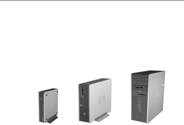
The HP Compaq dc7900 Business PC personal computers (Figure 2-1) deliver an outstanding combination of manageability, serviceability, and compatibility for enterprise environments. Based on the Intel processor with the Intel Q45 Express chipset, these systems emphasize performance along with industry compatibility. These models feature a similar architecture incorporating both PCI 2.3 and PCIe 1.1 buses. All models are easily upgradeable and expandable to keep pace with the needs of the office enterprise.
HP dc7900 USDT |
HP dc7900 SFF |
HP dc7900 CMT |
Figure 2-1. HP Compaq dc7900 Business PCs
This chapter includes the following topics:
■Features (2.2)
■System architecture (2.3)
■Specifications (2.4)
|
Technical Reference Guide |
www.hp.com |
2-1 |

System Overview
2.2 Features
The following standard features are included on all models unless otherwise indicated:
Intel processor in LGA775 (Socket T) package
Integrated graphics controller with dual monitor support:
One VGA connector
One DisplayPort (DP) connector with Multimode support
PC2-6400 and PC2-5300 (DDR2) DIMM support
Hard drive fault prediction
Eight USB 2.0-compliant ports
High definition (HD) audio processor with one headphone output, at least one microphone input, one line output, and one line input
Network interface controller providing 10/100/1000Base T support
Plug 'n Play compatible (with ESCD support)
Intelligent Manageability support
Management/security features including:
Flash ROM Boot Block
Diskette drive disable, boot disable, write protect
Power-on password
Administrator password
Serial port disable (SFF and CMT form factors only)
Smart Cover (hood) Sense
Smart Cover (hood) Lock (SFF and CMT form factors only)
USB port disable
Intel Standard Manageability support
Intel vPro Technology
HP Virtual Safe Browser
PS/2 enhanced keyboard
PS/2 optical scroll mouse
Energy Star compliancy met by all USDT form factors (Energy Star-qualified configurations of SFF and CMT form factors are available).
|
2-2 |
www.hp.com |
Technical Reference Guide |

System Overview
Table 2-1 shows the differences in features between the different PC series based on form factor:
Table 2-1
Feature Difference Matrix by Form Factor
|
USDT |
SFF |
CMT |
|
|
|
|
Processor types supported |
Intel Celeron, |
Intel Celeron, |
Intel Celeron, |
|
Pentium dual-core, |
Pentium dual-core, |
Pentium dual-core, |
|
Core 2 Duo |
Core 2 Duo, |
Core 2 Duo, |
|
|
Core 2 Quad |
Core 2 Quad |
|
|
|
|
Processor wattage (max) |
65 W |
95 W |
95 W |
|
|
|
|
Memory: |
|
|
|
# & type of sockets |
2 SODIMM |
4 DIMM |
4 DIMM |
Maximum memory |
8 GB |
16 GB |
16 GB |
|
|
|
|
Serial ports |
0 |
1 std., 1 opt. [1] |
1 std., 1 opt. [1] |
|
|
|
|
Parallel ports |
0 |
optional |
optional |
|
|
|
|
Drive bays: |
|
|
|
Externally accessible |
1 |
2 |
4 |
Internal |
1 |
1 |
2 |
|
|
|
|
Drive types supported |
1 HDD, |
2 HDDs, |
2 HDDs, |
|
1 slimline ODD |
1ODD, |
2 ODDs, |
|
|
RAID1 |
RAID1 |
|
|
|
|
PCIe slots: |
|
|
|
x16 graphics (PCIe 2.0) |
0 |
1 [3, 4] |
1 |
x1 connector |
1 [2] |
1 [3] |
1 |
x4 (x16 connector) |
|
1 [3, 4] |
1 |
|
|
|
|
PCI 2.3 32-bit 5-V slots |
0 |
1 half-height |
3 |
|
|
or |
full-height |
|
|
2 full-height [5] |
|
|
|
|
|
Power Supply Unit: |
|
|
|
Module type |
external |
internal |
internal |
power rating |
135-watt |
240-watt |
365-watt |
NOTES:
[1]2nd serial port requires optional cable/bracket assembly.
[2]PCIe Mini Card slot.
[3]Supports low-profile card in standard configuration. Not accessible if PCI riser card field option is installed.
[4]Accepts low-profile PCIe card: height = 2.5 in., length = 6.6 in.
[5]Full-height PCI slots require installation of PCI riser card field option (full-height dimensions: height = 4.2 in., length = 6.875 in).
|
Technical Reference Guide |
www.hp.com |
2-3 |

System Overview
2.3System Architecture
The systems covered in this guide feature an architecture based on the Intel Q45 Express chipset (Figure 2-2). All systems covered in this guide include the following key components:
■Intel Pentium Dual-Core, Core 2 Duo, Core 2 Quad, or Celeron processor.
■Intel Q45 Express chipset - Includes Q45 GMCH and 82801 ICH10-DO
■Super I/O (SIO) controller supporting PS/2 keyboard and mouse peripherals
■AD1884A audio controller supporting line in, line out, microphone in, and headphones out
■Intel 82567LM GbE network interface controller
The Q45 chipset provides a major portion of system functionality. Designed to complement the latest Intel processors, the Q45 GMCH integrates with the processor through a 800/1066/1333-MHz Front-Side Bus (FSB) and communicates with the ICH10-DO component through the Direct Media Interface (DMI). The integrated graphics controller of the Q45 on SFF and CMT systems can be upgraded through a PCI Express (PCIe) x16 graphics slot. All systems include a serial ATA (SATA) hard drive in the standard configuration.
Table 2-2 lists the differences between models by form factor.
Table 2-2.
Architectural Differences By Form Factor
Function |
USDT |
SFF |
CMT |
|
|
|
|
Memory sockets |
2 SODIMMs |
4 DIMMs |
4 DIMMs |
|
|
|
|
PCIe 2.0 x16 graphics slot |
No |
1 [1] |
1 |
|
|
|
|
PCIe x4 (x16 connector) graphics slot |
No |
1 [1] |
1 |
|
|
|
|
# of PCIe 1.1 x1 slots |
0 |
1 [1] |
1 |
|
|
|
|
# of PCI 2.3 slots |
0 |
1 [3] |
3 |
|
|
|
|
Serial port |
0 |
1 [4] |
1 [4] |
|
|
|
|
Parallel ports |
0 |
optional |
optonal |
|
|
|
|
SATA interfaces |
2 |
3 |
4 |
|
|
|
|
eSATA capability [2] |
No |
Yes |
Yes |
|
|
|
|
Notes:
[1]Low-profile slot. Not accessible if PCI riser is installed.
[2]Requires optional bracket/cable assembly.
[3]Low-profile slot in standard configuration. 2 full-height slots supported with optional PCI riser.
[4]2nd serial port possible with optional adapter.
|
2-4 |
www.hp.com |
Technical Reference Guide |

System Overview
|
|
|
|
|
|
|
|
|
|
|
|
|
Intel |
|
|
|
|
|
|
|
||||||
|
|
|
|
|
|
|
|
|
|
|
|
Processor |
|
|
|
|
|
|
|
|||||||
|
|
|
|
|
|
|
|
|
|
|
|
|
|
|
|
|
|
|
|
|
|
|
|
|
|
|
|
|
|
|
|
|
|
|
|
|
|
|
|
|
|
|
|
|
|
|
|
|
|
|
|||
|
|
|
|
|
|
|
|
|
|
|
|
|
|
|
|
|
800/1066/1333-MHz FSB |
|||||||||
|
|
|
|
|
|
|
|
|
|
|
|
|
|
|
|
|
|
|
|
|
|
|
|
|
|
|
|
|
|
|
|
|
|
|
|
|
|
|
|
|
|
|
|
|
|
|
|
|
|
|
|
|
|
|
|
|
|
|
|
|
|
|
|
|
|
|
|
|
|
|
|
|
|
|
|
|
|
|
|
|
Analog Mon. |
|
VGA |
|
|
|
|
|
|
|
|
|
|
|
|
|
|
|
|
Ch A DDR2 |
|||||||
|
DisplayPort |
Graphics |
Q45 |
SDRAM |
|
|
|
|
SDRAM |
|||||||||||||||||
Digital Mon. |
|
|
|
|
|
|||||||||||||||||||||
|
|
|
|
|
|
|||||||||||||||||||||
|
|
|
|
|
|
|
|
|
Cntlr. |
|
|
|
|
|
|
|||||||||||
|
|
|
|
|
|
|
|
|
|
|
GMCH |
Cntlr |
|
|
|
|
|
|||||||||
|
|
|
|
Switch |
|
|
|
|
|
|
|
Ch B DDR2 |
||||||||||||||
|
|
|
|
|
|
|
|
|
|
|
|
|
|
|
|
|
|
|
|
|
|
|
|
|
|
SDRAM |
|
|
|
|
|
|
|
|
|
|
|
|
|
|
|
|
|
|
|
|
|
|
|
|
|
|
|
|
|
|
|
|
|
|
|
|
|
|
|
|
|
|
|
|
|
|
|
|
|
|
|
|
|
|
|
|
|
|
|
|
|
|
|
|
|
|
|
|
|
|
|
|
|
|
|
|
|
|
|
|
|
PCI Express |
|
|
|
|
|
|
|
|
|
|
|
|
|
|
|
|
|
|
|
|
|
|
|
|
|
|
x16 slot (PEG) [2] |
|
|
|
|
|
|
|
|
|
|
DMI |
|
|
|
|
|
|
|
|
|||||||
|
|
|
|
|
|
|
|
|
|
|
|
|
|
|
|
|
|
|
|
|
|
|
|
|
|
|
|
|
|
|
|
|
|
|
|
|
|
|
|
|
|
|
|
|
|
|
|
|
|
|
|
|
|
|
|
|
|
|
|
|
|
|
|
|
|
|
|
|
|
|
|
|
|
|
|
|
|
|
|
|
SATA |
SATA |
DMI |
|
|
|
|
USB |
USB 2.0 |
|
||
Hard Drive |
|
|
|
||
|
SATA |
SATA |
I/F |
Ports (10) [5] |
|
Additional |
|
|
|
||
|
I/F [1] |
|
|
|
|
SATA |
|
|
|
|
|
|
|
|
Serial I/F [2] |
Parallel I/F [2] |
|
Devices |
SATA/eSATA |
82801 |
|
||
|
|
ICH10 |
LPC I/F |
SIO Controller |
|
AD1884A |
|
|
Kybd-Mouse I/F Diskette I/F [2] |
||
|
Audio |
Audio I/F |
|
||
Subsystem |
PCI Cntlr. |
|
|
|
|
|
|
|
|
|
|
|
|
|
|
Keyboard |
Diskette [2] |
|
|
|
|
Mouse |
|
|
|
NIC |
PCI 2.3 slots [3] |
|
|
|
|
I/F |
|
|
|
|
|
PCIe x1 slots [4] |
|
|
|
|
|
PCIe x4 (x16 conn.) [2] |
|
|
|
Power Supply
Notes:
[1]2 SATA ports in USDT, 3 SATA ports in SFF, 4 SATA ports in CMT, and 1 eSATA port in SFF and CMT.
[2]SFF and CMT only
[3]0 slots in USDT, 1 or 2 slots in SFF, 3 slots in CMT
[4]1 MiniCard slot in USDT, 1 slot in SFF and CMT
[5]8 ports accessible externally, 2 ports accessible internally
Figure 2-2. HP Compaq dc7900 Business PC Architecture, Block diagram
|
Technical Reference Guide |
www.hp.com |
2-5 |

System Overview
2.3.1 Intel Processor Support
The models covered in this guide are designed to support the following processor types:
■Intel Celeron: singleand dual-core performance
■Intel Pentium Dual-Core: Dual core performance
■Intel Core2 Duo: energy-efficient dual-core performance
■Intel Core2 Quad: energy efficient quad-core design
These processors are backward-compatible with software written for earlier x86 microprocessors and include streaming SIMD extensions (SSE, SSE2, and SSE3) for enhancing 3D graphics and speech processing performance. Intel processors with vPro Technology include hardware-based tools that allow corporate IT organizations to remotely manage and protect systems.
The system board includes a zero-insertion-force (ZIF) Socket-T designed for mounting an LGA775-type processor package.
CAUTION: The USDT form factor can support a processor rated up to 65 watts. The SFF and CMT form factors can support a processor rated up to 95 watts. Exceeding these limits can result in system damage and loss of data.
The processor heatsink/fan assembly mounting differs between form factors. Always use the same assembly or one of the same type when replacing the processor. Refer to the applicable Service Reference Guide for detailed removal and replacement procedures of the heatsink/fan assembly and the processor.
|
2-6 |
www.hp.com |
Technical Reference Guide |

System Overview
2.3.2 Chipset
The Intel Q45 Express chipset consists of a Graphics Memory Controller Hub (GMCH) and an enhanced I/O controller hub (ICH10-DO). Table 2-3 compares the functions provided by the chipsets.
|
Table 2-3 |
|
Chipset Components and Functionality |
|
|
Components |
Function |
|
|
Q45 GMCH |
Intel Graphics Media Accelerator 4500 (integrated graphics controller) |
|
PCIe 2.0 x16 graphics interface (1) |
|
SDRAM controller supporting unbuffered, non-ECC PC2-6400 DDR2 |
|
DIMMs or SODIMMs |
|
800-, 1066-, or 1333-MHz FSB |
|
|
82801 ICH10-DO |
PCI 2.3 bus I/F |
|
PCI Express x1 |
|
LPC bus I/F |
|
SMBus I/F |
|
SATA I/F |
|
HD audio interface |
|
RTC/CMOS |
|
IRQ controller |
|
Power management logic |
|
USB 1.1/2.0 controllers supporting 12 ports |
|
(these systems provide 8 external, 3 internal) |
|
Gigabit Ethernet controller |
|
|
The I/O controller hub (ICH10-DO) supports Intel vPro, which uses Active Management Technology (AMT). AMT is a hardware/firmware solution that operates on auxiliary power to allow 24/7 support of network alerting and management of the unit without regard to the power state or operating system. AMT capabilities include:
■System asset recovery (hardware and software configuration data)
■OS-independent system wellness and healing
■Software (virus) protection/management
|
Technical Reference Guide |
www.hp.com |
2-7 |

System Overview
2.3.3 Support Components
Input/output functions not provided by the chipset are handled by other support components. Some of these components also provide “housekeeping” and various other functions as well. Table 2-4 shows the functions provided by the support components.
Table 2-4
Support Component Functions
Component Name |
Function |
|
|
WPCD376H SIO Controller |
Keyboard and pointing device I/F |
|
Diskette I/F [1] |
|
Serial I/F (COM1and COM2) [2] |
|
Parallel I/F (LPT1, LPT2, or LPT3) [3] |
|
PCI reset generation |
|
Interrupt (IRQ) serializer |
|
Power button and front panel LED logic |
|
GPIO ports |
|
Processor over temperature monitoring |
|
Fan control and monitoring |
|
Power supply voltage monitoring |
|
SMBus and Low Pin Count (LPC) bus I/F |
|
|
Intel 82567LM Network Interface |
10/100/1000 Fast Ethernet network interface controller. |
Controller |
|
|
|
AD1884A HD Audio Codec |
Audio mixer |
|
Two digital-to-analog stereo converters |
|
Two analog-to-digital stereo converters |
|
Analog I/O |
|
Supports stereo (two-channel) audio streams |
NOTE:
[1]Not used in USDT form factor.
[2]Com1 supported only on SFF and CMT form factors. COM2 requires external bracket/cable assembly.
[3]Supported only on SFF and CMT form factors, requires external bracket/cable assembly.
2.3.4System Memory
These systems implement a dual-channel Double Data Rate (DDR2) memory architecture. All models support DDR2 800and 667-MHz DIMMs. The USDT system provides two SODIMM sockets supporting up to eight gigabytes of memory while the SFF and CMT form factors provide four DIMM sockets and support a total of 16 gigabytes of memory.
DDR and DDR2 DIMMs are NOT interchangeable.
SODIMM and DIMM components are NOT interchangeable.
|
2-8 |
www.hp.com |
Technical Reference Guide |

System Overview
2.3.5 Mass Storage
All models support at least two mass storage devices, with one being externally accessible for removable media. These systems provide the following interfaces for internal storage devices:
USDT: two SATA interfaces
SFF: three SATA interfaces and one eSATA port
CMT: four SATA interfaces and one eSATA port
These systems may be preconfigured or upgraded with a SATA hard drive and one removable media drive such as a CD-ROM drive.
2.3.6 Serial Interface
The SFF and CMT form factors include a serial port accessible at the rear of the chassis. The SFF and CMT form factors may be upgraded with a second serial port option. The serial interface is RS-232-C/16550-compatible and supports standard baud rates up to 115,200 as well as two high-speed baud rates of 230K and 460K.
2.3.7 Universal Serial Bus Interface
All models provide ten Universal Serial Bus (USB) ports. Two ports are accessible at the front of the unit, six ports are accessible on the rear panel, and two ports are accessible through a header on the system board. The SFF and CMT form factors support a media card reader module that connects to the internal header. These systems support USB 1.1 and 2.0 functionality on all ports.
BIOS Setup allows for the disabling of USB ports individually or in groups. In order to secure the system against a physical attack, ports may be disabled even if there is nothing physically connected to them, such as the two front ports for the media card reader module when the module is not present.
2.3.8 Network Interface Controller
All models feature an Intel gigabit Network Interface Controller (NIC) integrated on the system board. The controller provides automatic selection of 10BASE-T, 100BASE-TX, or 1000BASE-T operation with a local area network and includes power-down, wake-up, Alert-On-LAN (AOL), Alert Standard Format (ASF), and AMT features. An RJ-45 connector with status LEDs is provided on the rear panel.
|
Technical Reference Guide |
www.hp.com |
2-9 |

System Overview
2.3.9 Graphics Subsystem
These systems use the Q45 GMCH component, which includes an integrated graphics controller that can drive both an external VGA monitor and a DisplayPort digital display. The controller implements Dynamic Video Memory Technology (DVMT 3.0) for video memory. Table 2-5 lists the key features of the integrated graphics subsystem.
Table 2-5
Integrated Graphics Subsystem Statistics
|
Q45 GMCH |
|
Integrated Graphics Controller |
|
|
Recommended for |
Hi 2D, Entry 3D |
|
|
Bus Type |
Int. PCI Express |
|
|
Memory Amount |
32 MB pre-allocated |
|
|
Memory Type |
DVMT 3.0 |
|
|
DAC Speed |
400 MHz |
|
|
Maximum 2D Resolution |
2048x1536 @ 85 Hz |
|
|
Hardware Acceleration |
Quick Draw, |
|
DirectX 9, |
|
Direct Draw, |
|
Direct Show, |
|
Open GL 1.45, |
|
MPEG 1-2, |
|
Indeo |
|
|
Outputs |
1 VGA, 1 DisplayPort 1.1 [see text] |
All systems include a legacy VGA connector and a DisplayPort connector and support dual monitor operation. The DisplayPort includes a multimode feature that allows a DVI or VGA adapter to be connected to the DisplayPort.
These systems also include two PCIe graphics slots (one x16, one x4/x16 connector) to ensure full graphics upgrade capabilities.
2.3.10 Audio Subsystem
These systems use the integrated High Definition audio controller of the chipset and the ADI AD1884A High Definition audio codec. HD audio provides enhanced audio performance with higher sampling rates, refined signal interfaces, and audio processors with increased signal-to-noise ratio. The audio line input jack can be re-configured as a microphone input, and multi-streaming is supported. These systems include a 1.5-watt output amplifier driving an internal speaker, which can be muted with the F10 BIOS control. All models include front panel-accessible stereo microphone input and headphone output audio jacks.
|
2-10 |
www.hp.com |
Technical Reference Guide |

System Overview
2.4 Specifications
This section includes the environmental, electrical, and physical specifications for the systems covered in this guide. Where provided, metric statistics are given in parenthesis. Specifications are subject to change without notice.
Table 2-6
Environmental Specifications (Factory Configuration)
Parameter |
Operating |
Non-operating |
Ambient Air Temperature 50o to 95o F (10o to 35o C, max. rate of change < 10°C/Hr)
-22o to 140o F (-30o to 60o C, max. rate of change < 20°C/Hr)
Shock (w/o damage) |
|
5 Gs [1] |
20 Gs [1] |
|
|
|
|
Vibration |
0.000215 |
G2/Hz, 10-300 Hz |
0.0005 G2/Hz, 10-500 Hz |
|
|
|
|
Humidity |
10-90% |
Rh @ 28o C max. |
5-95% Rh @ 38.7o C max. |
|
wet bulb temperature |
wet bulb temperature |
|
|
|
|
|
Maximum Altitude |
10,000 ft (3048 m) [2] |
30,000 ft (9144 m) [2] |
|
|
|
|
|
NOTE: |
|
|
|
[1] Peak input acceleration during an 11 ms half-sine shock pulse. |
|
||
[2] Maximum rate of change: 1500 ft/min. |
|
||
Table 2-7 |
|
Power Supply Electrical Specifications |
|
|
|
Parameter |
Value |
|
|
Input Line Voltage: |
|
Nominal: |
100–240 VAC |
Maximum |
90–264 VAC |
|
|
Input Line Frequency Range: |
|
Nominal |
50–60 Hz |
Maximum |
47–63 Hz |
|
|
Energy Star 4.0 with 80Plus Bronze-level compliancy |
|
USDT |
Standard |
SFF & CMT |
Optional |
|
|
Maximum Continuous Power: |
|
USDT |
135 watts |
SFF |
240 watts |
CMT |
365 watts |
NOTE:
Energy Star 4.0 with 80Plus Bronze-level compliancy option available for SFF and CMT form factors.
|
Technical Reference Guide |
www.hp.com |
2-11 |

System Overview
Table 2-8
Physical Specifications
Parameter |
USDT [2] |
SFF [2] |
CMT [3] |
|
|
|
|
Height |
2.60 in |
3.95 in |
17.63 in |
|
(6.60 cm) |
(10.03 cm) |
(44.8 cm) |
|
|
|
|
Width |
9.90 in |
13.3 in |
7.0 in |
|
(25.15 cm) |
(33.78 cm) |
(16.8 cm) |
|
|
|
|
Depth |
10.0 in |
14.9 in |
17.8 in |
|
(25.40 cm) |
(37.85 cm) |
(45.21 cm) |
|
|
|
|
Weight [1] |
7.0 lb |
18.75 lb |
26.2 lb |
|
(3.18 kg) |
(8.50 kg) |
(11.89 kg) |
|
|
|
|
Load-bearing ability of |
77.1 lb |
77.1 lb |
77.1 lb |
chassis [4] |
(35 kg) |
(35 kg) |
(35 kg) |
NOTES:
[1]System configured with 1 hard drive, 1 diskette drive (SFF and CMT only), and no PCI cards.
[2]Desktop (horizontal) configuration.
[3]Minitower configuration. For desktop configuration, swap Height and Width dimensions.
[4]Applicable to unit in desktop orientation only and assumes reasonable type of load such as a monitor.
|
2-12 |
www.hp.com |
Technical Reference Guide |

System Overview
Table 2-9
Optical Drive Specifications
|
|
|
HP SuperMulti LightScribe |
Parameter |
DVD-ROM |
CD-RW/DVD-ROM Combo |
Combo |
|
|
|
|
Interface Type |
SATA [1] |
SATA [1] |
SATA [1] |
|
|
|
|
Max. read/write speeds |
DVD-RAM: 4x/na |
DVD-RAM: 12x/12x |
DVD-RAM: 12x/12x |
by media type |
DVD+RW: 8x/na |
DVD+RW: 8x/8x |
DVD+RW: 8x/8x |
|
DVD-RW: 8x/na |
DVD-RW: 8x/6x |
DVD-RW: 8x/6x |
|
DVD+R DL: 8x/na |
DVD+R DL: 8x/8x |
DVD+R DL: 8x/8x |
|
DVD-R DL: 8x/na |
DVD-R DL: 8x/8x |
DVD-R DL: 8x/8x |
|
DVD-ROM: 16x/na |
DVD-ROM: 16x/na |
DVD-ROM: 16x/na |
|
DVD+R: 8x/na |
DVD-ROM DL: 8x/na |
DVD-ROM DL: 8x/na |
|
DVD-R: 8x/na |
DVD+R: 16x/16x |
DVD+R: 16x/16x |
|
CD-ROM: 48x/na |
DVD-R: 16x/16x |
DVD-R: 16x/16x |
|
CD-RW: 32x/na |
CD-ROM: 48x/na |
CD-ROM: 48x/na |
|
CD-R: 48x/na |
CD-RW: 32x/32x |
CD-RW: 32x/32x |
|
|
CD-R: 48x/48x |
CD-R: 48x/48x |
|
|
|
|
Maximum Transfer Rate |
DVD:, 21.6 KB/s; |
DVD:, 21.6 KB/s; |
DVD:, 21.6 KB/s; |
(Reads) |
CD: 7.2 KB/s |
CD: 7.2 KB/s |
CD: 7.2 KB/s |
|
|
|
|
Media Capacity (DVD) |
DL: 8.5 GB, Std: 4.7 GB |
DL: 8.5 GB, Std: 4.7 GB |
DL: 8.5 GB, Std: 4.7 GB |
|
|
|
|
Average Access Time: |
|
|
|
Random |
DVD: <140 ms, CD: <125 |
DVD: <140 ms, CD: <125 ms |
DVD: <140 ms, CD: <125 ms |
Full Stroke |
ms |
DVD: <250 ms, CD: <210 ms |
DVD: <250 ms, CD: <210 ms |
|
DVD: <250 ms, CD: <210 |
|
|
|
ms |
|
|
|
|
|
|
Media lable creation? |
No |
No |
Yes [2] |
NOTE
[1]USDT models use “slim” drive.
[2]Requires special label-etchable media.
|
Technical Reference Guide |
www.hp.com |
2-13 |

System Overview
Table 2-10
Hard Drive Specifications
Parameter |
80 GB |
160 GB |
250 GB [4] |
|
|
|
|
Drive Size |
2.5 & 3.5 in.[1] |
2.5 & 3.5 in [1] |
3.5 in |
|
|
|
|
Interface |
SATA |
SATA |
SATA |
|
|
|
|
Transfer Rate |
1.5 & 3.0 Gb/s [2] |
1.5 & 3.0 Gb/s [2] |
3.0 Gb/s |
|
|
|
|
Drive Protection System |
Yes |
Yes |
Yes |
Support? |
|
|
|
|
|
|
|
Typical Seek Time (w/settling) |
|
|
|
Single Track |
0.8 ms |
0.8 ms |
1.0 ms |
Average |
9 ms |
9 ms |
11 ms |
Full Stroke |
17 ms |
17 ms |
18 ms |
|
|
|
|
Disk Format (logical blocks) |
156,301,488 |
320,173,056 |
488,397,168 |
|
|
|
|
Rotation Speed |
5400/7200/ |
5400/7200/ |
7200 RPM |
|
10K RPM [3] |
10K RPM [3] |
|
|
|
|
|
Drive Fault Prediction |
SMART IV |
SMART IV |
SMART IV |
NOTES:
[1]USDT supports 2.5-in. drives only.
[2]USDT supports 1.5 Gb/s drives only.
[3]USDT supports up to 7200-RPM drives only.
[4]Supported by SFF and CMT form factors only.
|
2-14 |
www.hp.com |
Technical Reference Guide |
Loading...