


 Loading...
Repair
GMAX™ II 5900 Convertible |
|
TexSpray™ 5900 HD |
|
Airless Sprayers |
311046H |
- For Portable Airless Spraying of Architectural Coatings and Paints -
3300 psi (22.8 MPa, 228 bar) Maximum Working Pressure
Important Safety Instructions
 Read all warnings and instructions in this manual. Save these instructions.
Model |
Series |
Description |
|
|
|
|
|
248691 |
A |
Standard |
|
|
|
|
|
248692 |
A |
Premium, with RAC® X tip, gun and hose |
|
|
|
|
|
248693 |
A |
Standard, with electric motor kit |
|
|
|
|
|
248694 |
A |
Same as 248693 except with ETL |
|
|
|
approval to CSA and UL standards |
|
|
|
|
|
248695 |
A |
Standard, with Lo-Boy suction set kit |
|
|
|
|
|
248696 |
A |
Premium, same as 248890 except with |
|
|
|
ETL approval to CSA and UL standards |
|
|
|
|
|
248697 |
A |
Standard, with Lo-Boy suction set kit and |
|
|
|
electric motor kit |
|
|
|
|
|
248889 |
A |
Premium, same as 248692 except with |
|
|
|
electric motor kit |
|
|
|
|
|
248890 |
A |
Premium, with RAC X tip, gun and hose |
|
|
|
and Lo-Boy suction set kit |
|
|
|
|
|
255630 |
A |
TexSpray 5900HD convertible with texture |
|
|
|
gun and hose |
|
|
|
|
|
255631 |
A |
Same as 255630 with electric motor kit |
ti11417a |
|
|
|
|
255954 |
A |
Same as 255630 except with electric |
|
|
|
motor kit that is ETL approved to CSA and |
|
|
|
UL standards |
|
|
|
|
|
245096 |
A |
KIT, electric motor, CSA |
|
|
|
|
|
245095 |
A |
KIT, electric motor, Non-CSA |
|
|
|
|
|
Related Manuals |
|
|
|
310892 |
311861 |
309469 |
|
308491 |
|||
|
|
||
310894 |
309640 |
|
Graco Inc. P.O. Box 1441 Minneapolis, MN 55440-1441
Copyright 2005, Graco Inc. is registered to I.S. EN ISO 9001
Manual Conventions
Contents
WARNING . . . . . . . . . . . . . . . . . . . . . . . . . . . . . . . . . 3
Maintenance . . . . . . . . . . . . . . . . . . . . . . . . . . . . . . . 5
Troubleshooting . . . . . . . . . . . . . . . . . . . . . . . . . . . . 6
Repair . . . . . . . . . . . . . . . . . . . . . . . . . . . . . . . . . . . . 8
Bearing Housing & Connecting Rod . . . . . . . . . . . 8
Drive Housing . . . . . . . . . . . . . . . . . . . . . . . . . . . . . . 9
Pinion Housing/Rotor/Shaft/Clutch/Pulley. . . . . . 10
Pressure Control . . . . . . . . . . . . . . . . . . . . . . . . . . 12
Displacement Pump . . . . . . . . . . . . . . . . . . . . . . . 15
Parts . . . . . . . . . . . . . . . . . . . . . . . . . . . . . . . . . . . . 18
Manual Conventions
WARNING
Hazard Symbol
WARNING: a potentially hazardous situation which, if not avoided, could result in death or serious injury.
Warnings in the instructions usually include a symbol indicating the hazard. Read the general Warnings section for additional safety information.
Standard Sprayer . . . . . . . . . . . . . . . . . . . . . . . . . . 18
Engine Detail . . . . . . . . . . . . . . . . . . . . . . . . . . . . . . 20
Pinion and Drive Housing . . . . . . . . . . . . . . . . . . . 21
Pressure Control and Filter . . . . . . . . . . . . . . . . . . 22
Clutch Housing . . . . . . . . . . . . . . . . . . . . . . . . . . . . 24
Premium Sprayer . . . . . . . . . . . . . . . . . . . . . . . . . . 25
Lo-Boy Suction Set. . . . . . . . . . . . . . . . . . . . . . . . . 26
Technical Data . . . . . . . . . . . . . . . . . . . . . . . . . . . . 27
Graco Standard Warranty . . . . . . . . . . . . . . . . . . . 28
CAUTION
CAUTION: a potentially hazardous situation which, if not avoided, may result in property damage or destruction of equipment.
Note
 Additional helpful information.
2 |
311046H |
Warning
Warning
The following are general warnings related to the setup, use, maintenance and repair of this equipment. Additional, more specific, warnings may be found throughout the text of this manual, where applicable.
 WARNING
FIRE AND EXPLOSION HAZARD
Flammable fumes, such as solvent and paint fumes, in work area can ignite or explode. To help prevent fire and explosion:
•Use equipment only in well ventilated area.Do not fill fuel tank while engine is running or hot; shut off engine and let it cool. Fuel is flammable and can ignite or explode if spilled on hot surface.
•Do not fill fuel tank while engine is running or hot; shut off engine and let it cool. Fuel is flammable and can ignite or explode if spilled on hot surface.
•When flammable liquid is sprayed or used for flushing or cleaning, keep sprayer at least 20 feet (6 m) away from explosive vapors.
•Eliminate all ignition sources; such as pilot lights, cigarettes, portable electric lamps, and plastic drop cloths (potential static arc).
•Keep work area free of debris, including solvent, rags and gasoline.
•Do not plug or unplug power cords, or turn power or light switches on or off when flammable fumes are present.
•Ground equipment and conductive objects in work area. See Grounding instructions.
•Use only grounded hoses.
•Hold gun firmly to side of grounded pail when triggering into pail.
•If there is static sparking or you feel a shock, stop operation immediately. Do not use equipment until you identify and correct the problem.
SKIN INJECTION HAZARD
High-pressure fluid from gun, hose leaks, or ruptured components will pierce skin. This may look like just a cut, but it is a serious injury that can result in amputation. Get immediate surgical treatment.
•Do not point gun at anyone or at any part of the body.
•Do not put your hand over the spray tip.
•Do not stop or deflect leaks with your hand, body, glove, or rag.
•Do not spray without tip guard and trigger guard installed.
•Engage trigger lock when not spraying.
•Follow Pressure Relief Procedure in this manual, when you stop spraying and before cleaning, checking, or servicing equipment.
PRESSURIZED EQUIPMENT HAZARD
Fluid from the gun/dispense valve, leaks, or ruptured components can splash in the eyes or on skin and cause serious injury.
•Follow Pressure Relief Procedure in this manual, when you stop spraying and before cleaning, checking, or servicing equipment.
•Tighten all fluid connections before operating the equipment.
•Check hoses, tubes, and couplings daily. Replace worn or damaged parts immediately.
MOVING PARTS HAZARD
Moving parts can pinch or amputate fingers and other body parts.
•Keep clear of moving parts.
•Do not operate equipment with protective guards or covers removed.
•Pressurized equipment can start without warning. Before checking, moving, or servicing equipment, follow the Pressure Relief Procedure in this manual. Disconnect power or air supply.
311046H |
3 |
Warning
 WARNING
EQUIPMENT MISUSE HAZARD
Misuse can cause death or serious injury.
•Do not exceed the maximum working pressure or temperature rating of the lowest rated system component. See Technical Data in all equipment manuals.
•Use fluids and solvents that are compatible with equipment wetted parts. See Technical Data in all equipment manuals. Read fluid and solvent manufacturer’s warnings.
•Check equipment daily. Repair or replace worn or damaged parts immediately.
•Do not alter or modify equipment.
•Use equipment only for its intended purpose. Call your Graco distributor for information.
•Route hoses and cables away from traffic areas, sharp edges, moving parts, and hot surfaces.
•Do not use hoses to pull equipment.
•Keep children and animals away from work area.
•Comply with all applicable safety regulations.
PRESSURIZED ALUMINUM PARTS HAZARD
Do not use 1,1,1-trichloroethane, methylene chloride, other halogenated hydrocarbon solvents or fluids containing such solvents in pressurized aluminum equipment. Such use can cause serious chemical reaction and equipment rupture, and result in death, serious injury, and property damage.
SUCTION HAZARD
Never place hands near the pump fluid inlet when pump is operating or pressurized. Powerful suction could cause serious injury.
CARBON MONOXIDE HAZARD
Exhaust contains poisonous carbon monoxide, which is colorless and odorless. Breathing carbon monoxide can cause death. Do not operate in an enclosed area.
TOXIC FLUID OR FUMES HAZARD
Toxic fluids or fumes can cause serious injury or death if splashed in the eyes or on skin, inhaled, or swallowed.
•Read MSDS’s to know the specific hazards of the fluids you are using.
•Store hazardous fluid in approved containers, and dispose of it according to applicable guidelines.
BURN HAZARD
Equipment surfaces and fluid that’s heated can become very hot during operation. To avoid severe burns, do not touch hot fluid or equipment. Wait until equipment/fluid has cooled completely.
PERSONAL PROTECTIVE EQUIPMENT
You must wear appropriate protective equipment when operating, servicing, or when in the operating area of the equipment to help protect you from serious injury, including eye injury, inhalation of toxic fumes, burns, and hearing loss. This equipment includes but is not limited to:
•Protective eyewear
•Clothing and respirator as recommended by the fluid and solvent manufacturer
•Gloves
•Hearing protection
RECOIL HAZARD
Brace yourself; gun may recoil when triggered and cause you to fall, which could cause serious injury.
4 |
311046H |
Maintenance
Maintenance
Pressure Relief Procedure
WARNING
Read Skin Injection Hazard, page 3; Burn Hazard, page 4
1.Lock gun trigger safety.
2.Turn engine ON/OFF switch to OFF.
3.Move pump switch to OFF and turn pressure control knob fully counterclockwise.
4.Unlock trigger safety. Hold metal part of gun firmly to side of grounded metal pail, and trigger gun to relieve pressure.
5.Lock gun trigger safety.
6.Open pressure drain valve. Leave valve open until ready to spray again.
If you suspect that the spray tip or hose is completely clogged, or that pressure has not been fully relieved after following the steps above, VERY SLOWLY loosen tip guard retaining nut or hose end coupling to relieve pressure gradually, then loosen completely. Now clear tip or hose.
CAUTION
For detailed engine maintenance and specifications, refer to separate Honda Engines Owner's Manual, supplied.
DAILY: Check engine oil level and fill as necessary.
DAILY: Check hoses for wear and damage.
DAILY: Check gun safety for proper operation.
DAILY: Check pressure drain valve for proper operation.
DAILY: Check and fill the gas tank.
DAILY: Check that V-belt (147) is centered on pulley and is not inverted. Replace if worn or damaged.
AFTER THE FIRST 20 HOURS OF OPERATION:
Drain engine oil and refill with clean oil. Reference Honda Engines Owner's Manual for correct oil viscosity.
WEEKLY: Remove engine air filter cover and clean element. Replace element, if necessary. If operating in an unusually dusty environment: check filter daily and replace, if necessary.
Replacement elements can be purchased from your local HONDA dealer.
WEEKLY: Check level of TSL in displacement pump packing nut. Fill nut, if necessary. Keep TSL in nut to help prevent fluid buildup on piston rod and premature wear of packings and pump corrosion.
AFTER EACH 100 HOURS OF OPERATION:
Change engine oil. Reference Honda Engines Owner's Manual for correct oil viscosity.
SPARK PLUG: Use only BPR6ES (NGK) or W20EPR-U (NIPPONDENSO) plug. Gap plug to 0.028 to 0.031 in. (0.7 to 0.8 mm). Use spark plug wrench when installing and removing plug.
311046H |
5 |
|
|
Troubleshooting |
|
Troubleshooting |
|
|
|
|
Problem |
Cause |
Solution |
|
|
|
|
|
|
E=XX is displayed |
Fault condition exists |
Determine fault correction from table, page 14 |
Engine will not start |
Engine switch is OFF |
Turn engine switch ON |
|
Engine is out of gasoline |
Refill gas tank. Honda Engines Owner's Man- |
|
|
ual. |
|
|
|
|
Engine oil level is low |
Try to start engine. Replenish oil, if necessary. |
|
|
Honda Engines Owner's Manual. |
|
|
|
|
Spark plug is disconnected of damaged |
Connect spark plug cable or replace spark plug |
|
Cold engine |
Use choke |
|
Fuel shutoff lever is OFF |
Move lever to ON position |
|
Oil is seeping into combustion chamber |
Remove spark plug. Pull starter 3 to 4 times. |
|
|
Clean or replace spark plug. Start engine. |
|
|
Keep sprayer upright to avoid oil seepage |
|
|
|
False tripping of WatchDog system. |
Operating conditions out of WatchDog |
Turn pressure down. Contact Graco Technical |
EMPTY is displayed. Pump does not |
parameters |
Assistance to adjust WatchDog parameters. |
run. |
Pump output is low, page 7. |
Operate without WatchDog active; Manual |
|
|
310892. |
|
|
|
Engine operates, but displacement |
Error code displayed |
Reference Pressure Control repair, page 14 |
pump does not operate |
|
|
Pump switch is OFF |
Turn pump switch ON |
|
|
Pressure setting too low |
Turn pressure adjusting knob clockwise to |
|
|
increase pressure. |
|
|
|
|
Fluid filter (29) is dirty |
Clean filter. Page 22. |
|
Tip or tip filter is clogged |
Clean tip or tip filter. Manual 309639. |
|
Displacement pump piston rod is stuck |
Repair pump. Manual 310894. |
|
due to dried paint |
|
|
|
|
|
Connecting rod is worn or damaged |
Replace connecting rod. Page 8. |
|
Drive housing is worn or damaged |
Replace drive housing. Page 9. |
|
Electrical power is not energizing clutch |
Check wiring connections. Page 12. |
|
field |
Reference pressure control repair. Page 14. |
|
|
|
|
|
Reference wiring diagram. Page 23. |
|
|
With pump switch ON and pressure turned to MAXI- |
|
|
MUM, use a test light to check for power between clutch |
|
|
test points on control board. |
|
|
Remove clutch wires from control board and |
|
|
measure resistance across clutch coil. At 70° F, |
|
|
the resistance must be between 1.2 +0.2Ω; if |
|
|
not, replace pinion housing. |
|
|
Have pressure control checked by authorized Graco |
|
|
dealer |
|
|
|
|
Clutch is worn, damaged, or incorrectly |
Adjust or replace clutch. Page 10. |
|
positioned |
|
|
|
|
|
pinion housing is worn or damaged |
Repair or replace pinion housing. Page10. |
6 |
311046H |
|
|
Troubleshooting |
|
|
|
Problem |
Cause |
Solution |
|
|
|
|
|
|
Pump output is low |
Strainer (82) is clogged |
Clean strainer. |
|
|
|
|
Piston ball (206) is not seating |
Service piston ball. Manual 310894. |
|
|
|
|
Piston packings are worn or damaged |
Replace packings. Manual 310894. |
|
|
|
|
O-ring (227) in pump is worn or damaged |
Replace o-ring. Manual 310894. |
|
|
|
|
Intake valve ball is not seating properly |
Clean intake valve. Manual 310894. |
|
|
|
|
Intake valve ball is packed with material |
Clean intake valve. Manual 310894. |
|
|
|
|
Engine speed is too low |
Increase throttle setting. Manual 310892. |
|
|
|
|
V-belt slipping |
Tighten V-belt with tension bar (132). Adjust |
|
|
bracket until it takes 15 lb of force to lock tension |
|
|
bar down |
|
|
|
|
Clutch is worn or damaged |
Adjust or replace clutch. Page 10. |
|
|
|
|
Pressure setting is too low |
Increase pressure. Manual 310892. |
|
|
|
|
Fluid filter (56), tip filter or tip is clogged or |
Clean filter. Manual 310892 or 309639. |
|
dirty |
|
|
|
|
|
Large pressure drop in hose with heavy |
Use larger diameter hose and/or reduce |
|
materials |
overall length of hose. Use of more than |
|
|
100 ft of 1/4 in. hose significantly reduces |
|
|
performance of sprayer. Use 3/8 in. hose |
|
|
for optimum performance (50 ft minimum). |
|
|
|
Excessive paint leakage into throat |
Throat packing nut is loose |
Remove throat packing nut spacer. Tighten |
packing nut |
|
throat packing nut just enough to stop leak- |
|
|
age. |
|
|
|
|
Throat packings are worn or damaged |
Replace packings. Manual 310894. |
|
|
|
|
Displacement rod is worn or damaged |
Replace rod. Manual 310894. |
|
|
|
Fluid is spitting from gun |
Air in pump or hose |
Check and tighten all fluid connections. Rep- |
|
|
rime pump. Manual 310892. |
|
|
|
|
Tip is partially clogged |
Clear tip. Manual 309639. |
|
|
|
|
Fluid supply is low or empty |
Refill fluid supply. Prime pump. Manual |
|
|
310892. Check fluid supply often to prevent |
|
|
running pump dry. |
|
|
|
Pump is difficult to prime |
Air in pump or hose |
Check and tighten all fluid connections. |
|
|
Reduce engine speed and cycle pump as |
|
|
slowly as possible during priming. |
|
|
|
|
Intake valve is leaking |
Clean intake valve. Be sure ball seat is not |
|
|
nicked or worn and that ball seats well. |
|
|
Reassemble valve. |
|
|
|
|
Pump packings are worn |
Replace pump packings. Manual 310894. |
|
|
|
|
Paint is too thick |
Thin the paint according to the supplier's |
|
|
recommendations |
|
|
|
|
Engine speed is too high |
Decrease throttle setting before priming |
|
|
pump. Manual 310892. |
|
|
|
Clutch squeaks each time clutch |
Clutch surfaces are not matched to each other |
Clutch surfaces need to wear into each other. |
engages |
when new and may cause noise |
Noise will dissipate after a day of run time. |
|
|
|
High engine speed at no load |
Misadjusted throttle setting |
Reset throttle to 3700 engine rpm at no load |
|
|
|
|
Worn engine governor |
Replace or service engine governor |
|
|
|
Gallon counter not working |
Bad sensor, broken or disconnected wire. |
Check connections. Replace sensor or |
|
Displaced or missing magnet. |
wire. Reposition or replace magnet. |
|
|
|
No display, sprayer operates |
Display damaged or has bad connection |
Check connections. Replace display. |
|
|
|
311046H |
7 |
Bearing Housing and Connecting Rod
Bearing Housing and Connecting Rod
Removal
WARNING
Read Skin Injection Hazard, page 3; Burn Hazard, page 4
1.Relieve pressure; page 5.
2.FIG. 1. Remove four screws (45) and front cover (44)
3.Remove pump. Refer to Displacement Pump, Removal, page 14.
4.Remove four screws (41) and washers (42) from bearing housing (40).
5.Pull connecting rod (43) and lightly tap lower rear of bearing housing with plastic mallet to loosen from drive housing (33). Pull bearing housing and connecting rod assembly off drive housing.
6.Inspect crank (B) and connecting rod (43) for excessive wear and replace parts as needed.
Installation
1.Evenly lubricate inside of bronze bearing (C) in bearing housing (40) with high-quality motor oil. Liberally pack top roller bearing (E), lower bearing (D) inside connecting rod (43) with bearing grease.
2.Assemble connecting rod (43) to bearing housing (40). Rotate connecting rod to lowest position.
3.Clean mating surfaces of bearing and drive housings.
4.Align connecting rod with crank (B) and carefully align locating pins in drive housing (33) with holes in bearing housing (40). Push bearing housing onto drive housing or tap into place with plastic mallet.
CAUTION
DO NOT use bearing housing screws (41) to align or seat bearing housing with drive housing. Align these parts with locating pins, to avoid premature bearing wear.
5.Install screws (41) and washers (42) in bearing housing. Torque evenly to note 3 value in Fig. 1.
6.Install pump. Refer to Displacement Pump, Installation, page 14.
B
38
E 2
2
44
33 |
D |
F  43
43
 42
42
45
1 C
|
41 |
3 |
|
40 |
|
87 |
88 |
|
|
|
|
A |
68 |
|
|
ti5739b |
|
1Oil
2Pack with bearing grease 114819
3Torque to 25 ft-lb (34 N.m)
FIG. 1
8 |
311046H |

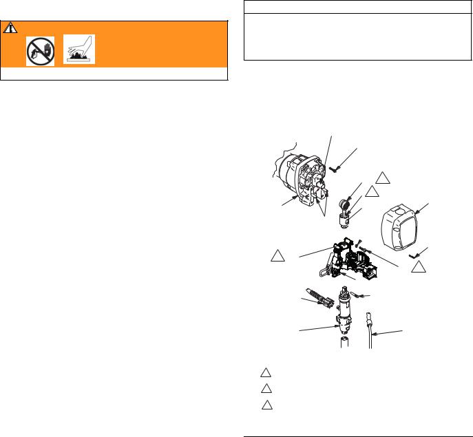
Drive Housing
Drive Housing
Removal
WARNING
Read Skin Injection Hazard, page 3; Burn Hazard, page 4
1.Relieve pressure; page 5.
2.Remove bearing housing. Refer to Bearing Housing and Connecting Rod, Removal, page 8.
CAUTION
Gallon counter sensor is connected to control board in pressure control. Pulling on the sensor wires could cause damage.
3.Premium sprayers: Remove two screws (108) and gallon counter sensor (39).
CAUTION
Thrust washers may stick to grease inside of drive housing. Do not lose or misplace.
4.Remove six screws (38).
5.Lightly tap around drive housing (33) to loosen drive housing. Pull drive housing straight off pinion housing. Be prepared to support combination gear (32) which may also come out.
Installation
1.FIG. 2. Apply all grease supplied with replacement gear cluster to gear cluster (32) and to areas called out by note 3.
2.FIG. 3. Ensure thrust washers are on combination gear (32) as shown.
3.Clean mating surfaces of pinion and drive housings.
4.Align gears and push new drive housing straight onto pinion housing (29) and locating pins (B).
5.Install six screws (38).
6.Install gallon counter sensor (39) with two screws (108).
7.Install bearing housing. Refer to Bearing Housing and Connecting Rod, Installation, page 8.
CAUTION
DO NOT use drive housing screws (18) to align or seat bearing housing with drive housing. Align these parts with locating pins, to avoid premature bearing wear.
8.Install screws (18) in drive housing. Torque evenly to note 3 value in Fig. 1.
9.Install pump. Refer to Displacement Pump, Installation, page14.
B
29
3
33a
33b
32
31
33 1
38
ti5740a
B30
30
3 |
|
2 |
39 |
1 Torque to 25 ft-lb (34 N.m) |
22 |
|
2 Gallon counter sensor
3 Pack with grease 114819
FIG. 2
30,30a 1 |
|
|
|
|
30 |
1 |
|
32 |
|
1 |
Steel |
2 31 |
ti6252a |
2 |
Copper |
|
|
|
FIG. 3
311046H |
9 |
Loading...