


 Loading...
Contents
HP E8491A IEEE 1394 PC Link to VXI Configuration and User’s Guide
Edition 1 |
|
Safety Symbols ............................................................................................................. |
6 |
WARNINGS ................................................................................................................. |
6 |
Declaration of Conformity............................................................................................ |
7 |
Reader Comment Sheet ................................................................................................ |
9 |
Chapter 1 |
|
Introduction .................................................................................................................. |
11 |
Using the IEEE 1394 Serial Bus in VXI Systems ...................................................... |
11 |
Component Overview ......................................................................................... |
11 |
The HP E8491A PC Link to VXI Interconnect ............................................ |
11 |
The Adaptec® AHA-8940 1394-to-PCI Host Adapter ................................ |
11 |
The HP I_O Libraries ................................................................................... |
11 |
Using this Manual .............................................................................................. |
11 |
Chapter 2: Interface Installation and Configuration ..................................... |
11 |
Chapter 3: VXI Programming Using the IEEE 1394 Serial Bus .................. |
12 |
Chapter 4: IEEE 1394 Fundamentals and Interface Overview ..................... |
12 |
Appendix A: Specifications .......................................................................... |
12 |
Appendix B: Editing the HP E8491A Resource Manager Configuration .... |
12 |
Additional Information ........................................................................................ |
12 |
Chapter 2 |
|
Interface Installation and Configuration ................................................................... |
13 |
Using this Chapter ...................................................................................................... |
13 |
Step 1: Installing the IEEE 1394Host Adapter .................................................... |
13 |
Where to go Next .......................................................................................... |
17 |
Step 2: Installing the HP E8491A Interconnect .................................................. |
17 |
Alternate Configurations .............................................................................. |
19 |
Where to go Next .......................................................................................... |
20 |
Step 3: Installing VXI Instruments ...................................................................... |
20 |
Installing C-size Instruments ........................................................................ |
20 |
Installing A- and B-size Instruments ............................................................ |
22 |
Step 4: Installing the HP I_O Libraries ............................................................... |
24 |
Configuring the HP E8491A Interconnect ................................................... |
25 |
Editing the HP E8491A Configuration ......................................................... |
27 |
Editing the HP E8491A Configuration on Windows 95 Platforms .............. |
28 |
Step 5: Installing the HP VXIplug&play Instrument Drivers ............................. |
28 |
Step 6. Verifying the Installation ........................................................................ |
29 |
Using Instrument Soft Front Panels .............................................................. |
29 |
Viewing the Resource Manager Output ....................................................... |
30 |
Running the Resource Manager .......................................................................... |
33 |
Contents 1

Chapter 3 |
|
VXI Programming Using the IEEE 1394 Serial Bus ................................................ |
35 |
Using this Chapter ...................................................................................................... |
35 |
Programming Register-Based and Message-Based VXI Instruments ................. |
35 |
Opening Instrument Sessions .............................................................................. |
35 |
Optimizing Programs .......................................................................................... |
36 |
Block Data Transfers .................................................................................... |
36 |
Block Transfers using HP VXIplug&play Drivers ....................................... |
37 |
Block Transfers using HP VISA ................................................................... |
40 |
HP E8491A Triggering ....................................................................................... |
43 |
Using Triggers .............................................................................................. |
43 |
Configuring the E8491A Trig In and Trig Out Ports ................................... |
44 |
Triggering Example ...................................................................................... |
45 |
Trigger Pull Up ............................................................................................. |
47 |
Using HP E8491A Shared Memory .................................................................... |
47 |
Locating E8491A Shared Memory ............................................................... |
47 |
Example Programs .............................................................................................. |
49 |
Storing Readings in Shared Memory - HP VISA Example .......................... |
50 |
Storing Readings in Shared Memory - SICL Example ................................ |
54 |
Chapter 4 |
|
IEEE 1394 Fundamentals and |
|
Interface Overview ...................................................................................................... |
57 |
Using this Chapter ...................................................................................................... |
57 |
IEEE 1394 Topology and Terminology .............................................................. |
57 |
Features of the IEEE 1394 Bus ..................................................................... |
58 |
Optimizing the Configuration ....................................................................... |
59 |
IEEE 1394 Data Transfer Protocol ...................................................................... |
59 |
Asynchronous Data Transfers ....................................................................... |
60 |
Fair Arbitration Protocol ............................................................................... |
60 |
VXI Data Transfers ....................................................................................... |
60 |
The Adaptec® AHA-8940 Host Adapter and Interface Cable ............................ |
61 |
The HP E8491A PC to VXI Interconnect ........................................................... |
62 |
Using the HP E8491A with the HP E1406 Command Module .................... |
64 |
The HP I_O Libraries .......................................................................................... |
64 |
Appendix A |
|
Specifications ................................................................................................................ |
65 |
Interface Characteristics ...................................................................................... |
65 |
VXI Characteristics ............................................................................................. |
65 |
General .......................................................................................................... |
65 |
CLK 10 ......................................................................................................... |
66 |
External Trigger Input .................................................................................. |
66 |
External Trigger Output ................................................................................ |
66 |
Trigger Delays .............................................................................................. |
67 |
Cooling ......................................................................................................... |
67 |
Power Supply Loading ................................................................................. |
67 |
2 Contents

Appendix B |
|
Editing the HP E8491A Resource Manager Configuration ..................................... |
69 |
Introduction................................................................................................................. |
69 |
Configuration File Overview .............................................................................. |
69 |
The names.cf Configuration File .................................................................. |
72 |
The oride.cf Configuration File .................................................................... |
72 |
The vmedev.cf Configuration File ................................................................ |
72 |
The cmdrsrvt.cf Configuration File .............................................................. |
72 |
The dynamic.cf Configuration File ............................................................... |
72 |
The irq.cf Configuration File ........................................................................ |
73 |
The ttltrig.cf Configuration File ................................................................... |
73 |
The vximanuf.cf Configuration File ............................................................. |
73 |
The vximodel.cf Configuration File ............................................................. |
73 |
Utility Function Overview .................................................................................. |
73 |
Using ivxisc .................................................................................................. |
73 |
Using iclear ................................................................................................... |
75 |
Index ................................................................................................................................ |
77 |
Contents 3

4 Contents

HEWLETT-PACKARD WARRANTY STATEMENT
HP PRODUCT: HP E8491A I E E E 1394 PC LINK to VXI |
DURATION OF WARRANTY: |
3 years |
|
1.HP warrants HP hardware, accessories and supplies against defects in materials and workmanship for the period specified above. If HP receives notice of such defects during the warranty period, HP will, at its option, either repair or replace products which prove to be defective. Replacement products may be either new or like-new.
2.HP warrants that HP software will not fail to execute its programming instructions, for the period specified above, due to defects in material and workmanship when properly installed and used. If HP receives notice of such defects during the warranty period, HP will replace software media which does not execute its programming instructions due to such defects.
3.HP does not warrant that the operation of HP products will be interrupted or error free. If HP is unable, within a reasonable time, to repair or replace any product to a condition as warranted, customer will be entitled to a refund of the purchase price upon prompt return of the product.
4.HP products may contain remanufactured parts equivalent to new in performance or may have been subject to incidental use.
5.The warranty period begins on the date of delivery or on the date of installation if installed by HP. If customer schedules or delays HP installation more than 30 days after delivery, warranty begins on the 31st day from delivery.
6.Warranty does not apply to defects resulting from (a) improper or inadequate maintenance or calibration, (b) software, interfacing, parts or supplies not supplied by HP, (c) unauthorized modification or misuse, (d) operation outside of the published environmental specifications for the product, or (e) improper site preparation or maintenance.
7.TO THE EXTENT ALLOWED BY LOCAL LAW, THE ABOVE WARRANTIES ARE EXCLUSIVE AND NO OTHER WARRANTY OR CONDITION, WHETHER WRITTEN OR ORAL, IS EXPRESSED OR IMPLIED AND HP SPECIFICALLY DISCLAIMS ANY IMPLIED WARRANTY OR CONDITIONS OF MERCHANTABILITY, SATISFACTORY QUALITY, AND FITNESS FOR A PARTICULAR PURPOSE.
8.HP will be liable for damage to tangible property per incident up to the greater of $300,000 or the actual amount paid for the product that is the subject of the claim, and for damages for bodily injury or death, to the extent that all such damages are determined by a court of competent jurisdiction to have been directly caused by a defective HP product.
9.TO THE EXTENT ALLOWED BY LOCAL LAW, THE REMEDIES IN THIS WARRANTY STATEMENT ARE CUSTOMER’S SOLE AND EXLUSIVE REMEDIES. EXCEPT AS INDICATED ABOVE, IN NO EVENT WILL HP OR ITS SUPPLIERS BE LIABLE FOR LOSS OF DATA OR FOR DIRECT, SPECIAL, INCIDENTAL, CONSEQUENTIAL (INCLUDING LOST PROFIT OR DATA), OR OTHER DAMAGE, WHETHER BASED IN CONTRACT, TORT, OR OTHERWISE.
FOR CONSUMER TRANSACTIONS IN AUSTRALIA AND NEW ZEALAND: THE WARRANTY TERMS CONTAINED IN THIS STATEMENT, EXCEPT TO THE EXTENT LAWFULLY PERMITTED, DO NOT EXCLUDE, RESTRICT OR MODIFY AND ARE IN ADDITION TO THE MANDATORY STATUTORY RIGHTS APPLICABLE TO THE SALE OF THIS PRODUCT TO YOU.
U.S. Government Restricted Rights
The Software and Documentation have been developed entirely at private expense. They are delivered and licensed as "commercial computer software" as defined in DFARS 252.2277013 (Oct 1988), DFARS 252.211-7015 (May 1991) or DFARS 252.227-7014 (Jun 1995), as a "commercial item" as defined in FAR 2.101(a), or as "Restricted computer software" as defined in FAR 52.227-19 (Jun 1987)(or any equivalent agency regulation or contract clause), whichever is applicable. You have only those rights provided for such Software and Documentation by the applicable FAR or DFARS clause or the HP standard software agreement for the product involved.
HP E8491A IEEE 1394 PC Link to VXI Configuration and User’s Guide
Edition 1
Copyright © 1998 Hewlett-Packard Company. All Rights Reserved.
5
Documentation History
All Editions and Updates of this manual and their creation date are listed below. The first Edition of the manual is Edition 1. The Edition number increments by 1 whenever the manual is revised. Updates, which are issued between Editions, contain replacement pages to correct or add additional information to the current Edition of the manual. Whenever a new Edition is created, it will contain all of the Update information for the previous Edition. Each new Edition or Update also includes a revised copy of this documentation history page.
Edition 1 . . . . . . . . . . . . . . . . . . . . . . . . . . . . . . . . . . . . . . . . . . . . . . . .June 1998
Safety Symbols
Instruction manual symbol affixed to product. Indicates that the user must refer to the manual for specific WARNING or CAUTION information to avoid personal injury or damage to the product.
Indicates the field wiring terminal that must be connected to earth ground before operating the equipment—protects against electrical shock in case of fault.
Frame or chassis ground terminal—typically or  connects to the equipment's metal frame.
WARNING
CAUTION
Alternating current (AC)
Direct current (DC).
Indicates hazardous voltages.
Calls attention to a procedure, practice, or condition that could cause bodily injury or death.
Calls attention to a procedure, practice, or condition that could possibly cause damage to equipment or permanent loss of data.
WARNINGS
The following general safety precautions must be observed during all phases of operation, service, and repair of this product. Failure to comply with these precautions or with specific warnings elsewhere in this manual violates safety standards of design, manufacture, and intended use of the product. Hewlett-Packard Company assumes no liability for the customer's failure to comply with these requirements.
Ground the equipment: For Safety Class 1 equipment (equipment having a protective earth terminal), an uninterruptible safety earth ground must be provided from the mains power source to the product input wiring terminals or supplied power cable.
DO NOT operate the product in an explosive atmosphere or in the presence of flammable gases or fumes.
For continued protection against fire, replace the line fuse(s) only with fuse(s) of the same voltage and current rating and type. DO NOT use repaired fuses or short-circuited fuse holders.
Keep away from live circuits: Operating personnel must not remove equipment covers or shields. Procedures involving the removal of covers or shields are for use by service-trained personnel only. Under certain conditions, dangerous voltages may exist even with the equipment switched off. To avoid dangerous electrical shock, DO NOT perform procedures involving cover or shield removal unless you are qualified to do so.
DO NOT operate damaged equipment: Whenever it is possible that the safety protection features built into this product have been impaired, either through physical damage, excessive moisture, or any other reason, REMOVE POWER and do not use the product until safe operation can be verified by service-trained personnel. If necessary, return the product to a Hewlett-Packard Sales and Service Office for service and repair to ensure that safety features are maintained.
DO NOT service or adjust alone: Do not attempt internal service or adjustment unless another person, capable of rendering first aid and resuscitation, is present.
DO NOT substitute parts or modify equipment: Because of the danger of introducing additional hazards, do not install substitute parts or perform any unauthorized modification to the product. Return the product to a Hewlett-Packard Sales and Service Office for service and repair to ensure that safety features are maintained.
6

Declaration of Conformity
according to ISO/IEC Guide 22 and EN 45014
Manufacturer’s Name: |
Hewlett-Packard Company |
|
Loveland Manufacturing Center |
Manufacturer’s Address: |
815 14th Street S.W. |
|
Loveland, Colorado 80537 |
declares, that the product:
Product Name: |
IEEE 1394 PC Link to VXI |
Model Number: |
HP E8491A |
Product Options: |
All |
conforms to the following Product Specifications:
Safety: IEC 1010-1 (1990) Incl. Amend 1 (1992)/EN61010-1 (1993)
CSA C22.2 #1010.1 (1992)
UL 3111-1 (1994)
EMC: CISPR 11:1990/EN55011 (1991): Group1 Class A IEC 801-2:1991/EN50082-1 (1992): 4kVCD, 8kVAD IEC 801-3:1984/EN50082-1 (1992): 3 V/m
IEC 801-4:1988/EN50082-1 (1992): 1kV Power Line
.5kV Signal Lines
Supplementary Information: The product herewith complies with the requirements of the Low Voltage Directive 73/23/EEC and the EMC Directive 89/336/EEC (inclusive 93/68/EEC) and carries the "CE" mark accordingly.
Tested in a typical configuration in an HP C-Size VXI mainframe.
June, 1998 |
Jim White, QA Manager |
European contact: Your local Hewlett-Packard Sales and Service Office or Hewlett-Packard GmbH, Depart-
ment HQ-TRE, Herrenberger Straße 130, D-71034 Böblingen, Germany (FAX +49-7031-14-3143)
7

Notes:
8
Please fold and tape for mailing
Reader Comment Sheet
HP E8491A IEEE 1394 PC Link to VXI Configuration and User’s Guide Edition 1
You can help us improve our manuals by sharing your comments and suggestions. In appreciation of your time, we will enter you in a quarterly drawing for a Hewlett-Packard Palmtop Personal Computer (U.S. government employees are not eligible for the drawing).
Your Name
Company Name
Job Title
Address
City, State/Province
Country
Zip/Postal Code
Telephone Number with Area Code
Please list the system controller, operating system, programming language, and plug-in modules you are using.
fold here
cut along this line
NO POSTAGE
NECESSARY
IF MAILED
IN THE
UNITED STATES
BUSINESS REPLY MAIL
FIRST CLASS PERMIT NO. 37 LOVELAND, CO
POSTAGE WILL BE PAID BY ADDRESSEE
HEWLETT-PACKARD COMPANY
Measurement Systems Division
Learning Products Department
P.O. Box 301
Loveland, CO 80539-9984
|
fold here |
|
|
|
|
Please pencil-in one circle for each statement below: |
Disagree |
|
|
|
Agree |
|
|
|
|||
• The documentation is well organized. |
O |
O |
O |
O |
O |
• Instructions are easy to understand. |
O |
O |
O |
O |
O |
• The documentation is clearly written. |
O |
O |
O |
O |
O |
• Examples are clear and useful. |
O |
O |
O |
O |
O |
• Illustrations are clear and helpful. |
O |
O |
O |
O |
O |
• The documentation meets my overall expectations. |
O |
O |
O |
O |
O |
Please write any comments or suggestions below–be specific.
Chapter 1
Introduction
Using the IEEE 1394 Serial Bus in VXI Systems
Component
Overview
The HP E8491A PC Link
to VXI Interconnect
The Adaptec® AHA-8940
1394-to-PCI Host Adapter
The IEEE 1394 Serial Bus (FireWire) is a high-speed bus that has been implemented as an I/O interface between external PCs and HP VXI systems. The bus links the PC backplane to the VXI mainframe backplane. This manual describes the implementation, configuration, and use of this interface.
Implementation of the IEEE 1394 serial bus as an I/O interface for HP VXI systems is provided through three components:
•HP E8491A PC Link to VXI Interconnect
•Adaptec® AHA-8940 1394-to-PCI Host Adapter
•HP I_O Libraries
The HP E8491A is the VXI hardware that links the VXI mainframe backplane to the IEEE 1394 serial bus. The E8491A is a 1-slot, C-size, message-based device that is installed in mainframe slot 0.
The Adaptec® AHA-8940 1394-to-PCI Host Adapter card is installed in the PC and links the computer’s (PCI) backplane to the IEEE 1394 bus. The AHA-8940 has one internal and two external IEEE 1394 ports and can support up to 16 HP E8491As.
The HP I_O Libraries The HP I_O Libraries provide the HP VISA and HP SICL drivers required to use the HP E8491A. Included with the libraries are the drivers for the
Adaptec® AHA-8940 host adapter.
Using this Manual This manual is organized to help you install, configure, and begin using the IEEE 1394 serial bus as quickly and efficiently as possible. The following information outlines the contents of the other chapters, and identifies the areas of programming a VXI system that are NOT covered in this manual.
Chapter 2: Interface
Installation and
Configuration
This chapter contains information on installing the HP E8491A hardware and its drivers (the HP I_O Libraries). Also included is information on installing VXI instruments, installing HP VXIplug&play drivers, and on verifying the system.
Chapter 1 |
Introduction 11 |

Chapter 3: VXI
Programming Using the
IEEE 1394 Serial Bus
This chapter contains the information necessary to begin communicating with VXI instruments through the HP E8491A and IEEE 1394 serial bus. The chapter contains information on optimizing system performance using block data transfers, and also covers triggering and using HP E8491A shared memory.
Chapter 4: IEEE 1394
Fundamentals and
Interface Overview
Appendix A:
Specifications
Appendix B: Editing the
HP E8491A Resource
Manager Configuration
Additional
Information
This chapter describes the IEEE 1394 serial bus and how it is implemented in HP VXI systems. It defines the bus terminology and data transfer protocol.
Appendix A contains the operating and performance specifications of the HP E8491A.
Appendix B contains information on editing your VXI system configuration as set by the resource manager. It describes selected configuration files and utility functions used to view and modify your configuration.
Programming the HP E8491A is through HP VISA and HP SICL functions. Although this manual identifies the specific functions used, you will need to refer to the HP VISA and HP SICL manuals for detailed information.
Also, included with the HP I_O Libraries is the utility ‘I_O Config’. This utility is used to configure the HP E8491A and has a help file associated with it.
12 Introduction |
Chapter 1 |

Chapter 2
Interface Installation and Configuration
Using this Chapter
Step 1: Installing
the IEEE 1394
Host Adapter
Note
This chapter contains information necessary to install and configure the IEEE 1394 host adapter (if required) and the HP E8491A interconnect. The installation sequence and other topics covered in this chapter are as follows:
• |
Step 1: Installing the IEEE 1394 Host Adapter . . . . . . . . . . |
13 |
• |
Step 2: Installing the HP E8491A Interconnect . . . . . . . . . . |
18 |
• |
Step 3: Installing VXI Instruments . . . . . . . . . . . . . . . . . . . . |
22 |
• |
Step 4: Installing the HP I_O Libraries. . . . . . . . . . . . . . . . . |
26 |
• |
Step 5: Installing HP VXIplug&play Instrument Drivers. . . |
30 |
• |
Step6: Verifying the Installation . . . . . . . . . . . . . . . . . . . . . . |
31 |
• |
Running the Resource Manager . . . . . . . . . . . . . . . . . . . . . . |
35 |
The IEEE 1394 adapter shipped as Option 001 to the HP E8491A is the
Adaptec® AHA-8940 1394-to-PCI Host Adapter. Included with the adapter is a cable for powering 1394 devices and a 4.5m interface cable.
If your personal computer (PC) currently has an Adaptec® IEEE-1394 host adapter or built-in IEEE-1394 port, proceed to Step 2: Installing the HP E8491 Interconnect.
The layout of the Adaptec® host adapter is shown in Figure 2-1.
Chapter 2 |
Interface Installation and Configuration 13 |
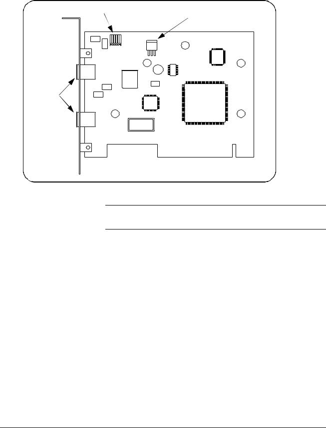
12 VDC power connector |
Internal IEEE 1394 connector |
|
External
IEEE 1394 connectors
Figure 2-1. Layout of the Adaptec® AHA-8940 1394-to-PCI Host Adapter.
WARNING Turn off and disconnect the power to your computer and to any peripheral devices before installing the host adapter.
A.Remove the computer chassis cover to expose the expansion slots and external access covers.
B.Locate an unused, unobstructed PCI bus expansion slot (Figure 2-2) that supports bus mastering. (PCI bus slots are usually white or ivory.) See your computer documentation to determine if the PCI slot supports bus mastering.
14 Interface Installation and Configuration |
Chapter 2 |
PCI expansion slots (usually white or ivory)
 shared slot
Figure 2-2. Locating a PCI bus Expansion Slot.
Note Many computer PCI systems have one pair of ISA and PCI slots close to each other. This saves space and allows you to install either an ISA card or a PCI card in the slot pair.
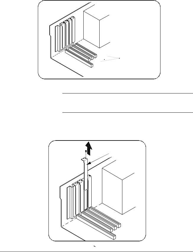
C.Remove the corresponding expansion slot cover from the computer chassis (Figure 2-3).
expansion slot cover
Figure 2-3. Removing the PC Expansion Slot Cover.
Chapter 2 |
Interface Installation and Configuration 15 |
D.Align the bus contacts on the bottom of the host adapter with the PCI bus slot. Carefully, but firmly, press the adapter into the slot.
host adapter
Figure 2-4. Installing the Host Adapter.
E.Secure the host adapter bracket to the computer chassis with the screw from the expansion slot cover removed in step C.
Connecting the Power Cable
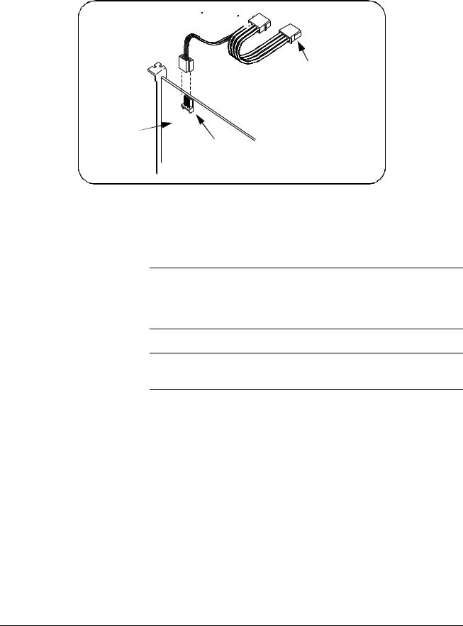
F.Connect the power cable between the adapter and the PC as shown in Figure 2-5. This provides power from the adapter to devices along the interface via the interface cable. This allows you to cycle power on any VXI mainframe in multi-frame systems without affecting other
frames. The power is also available to other IEEE 1394 devices that may be part of the interface network. The Adaptec® host adapter is capable of supplying 12V with a maximum current draw of 1.5 amps.
16 Interface Installation and Configuration |
Chapter 2 |
power in  (from system power supply)
power out (to disk drives)
host adapter
12V DC power connector
Figure 2-5. Connecting the Power Cable Between the PC and the Host Adapter.
G.Replace the computer cover. Connect one end of the interface cable to either of the adapter’s external connectors. You can now turn on the PC.
Note When power is applied, Windows 95 operating systems may detect the
Adaptec® card and indicate that it cannot locate an associated .inf file. Ignore this message as the .inf file is installed when the HP I_O Libraries are installed (Step 4).
Note
Where to go Next
Step 2: Installing
the HP E8491A
Interconnect
Refer to Chapter 4: IEEE 1394 Fundamentals and Interface Overview for more information on the Adaptec® host adapter.
If you are installing the IEEE 1394 interface for the first time, continue with “Step 2: Installing the HP E8491A Interconnect.” If the E8491A and your VXI instruments are already installed, proceed to “Step 4: Installing the
HP I_O Libraries.” Notice that the HP I_O Libraries contain the Adaptec ® host adapter drivers.
The HP E8491A interconnect links the IEEE 1394 bus to the backplane of the VXI mainframe. The E8491A is a C-size device with VXI Resource Manager and Slot 0 capability.
There are no configuration switches on the E8491A. The device’s logical address is 0 and it provides the system’s resource manager functionality via software that is part of the HP I_O Libraries. Its VXI servant area is 255, therefore; it is the interface to all VXI devices with logical addresses between 1 and 255. The E8491A is normally, but not required to be, installed in mainframe slot 0.
Chapter 2 |
Interface Installation and Configuration 17 |

Note Refer to “Alternate Configurations” for information on using the E8491A with the HP E1406 Command Module and using it in VXI-MXI systems.
A.If turned on, turn off the VXI mainframe and disconnect all power sources that may be applied to any instruments.
B.Insert the E8491A into mainframe slot 0 by aligning the module with the guides inside the mainframe (Figure 2-6). Slowly push the module into the slot until it seats in the backplane connectors. It may be necessary to pull out (not remove) the retaining screws in order to seat the device securely in the connectors.
seat the module by pushing in the extraction levers
extraction levers
retaining screws
slide the module into the mainframe until it plugs into the
backplane connectors
Figure 2-6. Installing the HP E8491A in the VXI Mainframe.
18 Interface Installation and Configuration |
Chapter 2 |
C. Tighten the retaining screws on the top and bottom of the module.
Connecting the HP E8491A to the Host Adapter
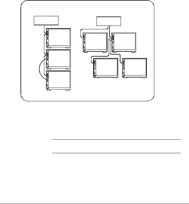
D.Connect the interface cable from the host adapter to E8491A port A, B, or C. The ports are identical and unused ports are available to connect additional E8491As and other IEEE 1394 devices in a daisy-chain or tree configuration (Figure 2-7). Notice that there can be no closed loops.
DAISY-CHAIN CONFIGURATION |
TREE CONFIGURATION |
|
PC |
PC |
|
VXI |
|
|
|
VXI |
VXI |
VXI |
|
|
* |
VXI |
VXI |
|
|
|
VXI |
|
|
* A second connection creates a closed loop and is not allowed
Figure 2-7. IEEE 1394 Interface Configurations.
I/O performance is impacted slightly by the hardware configuration.The VXI mainframe with the fewest number of hops (cable links) to the PC has the highest priority. However, each mainframe has equal access to the bus during each data transfer interval.
Note Refer to Chapter 4: IEEE 1394 Fundamentals and Interface Overview for information on the topology and terms associated with the IEEE 1394 bus.
Alternate Configurations Certain applications may include the HP E1406A Command Module as an HP-IB interface to selected instruments. In this configuration, the E8491A must be the resource manager since its logical address is always 0. It is generally installed in mainframe slot 0 so that it also provides the system’s slot 0 functionality.
Chapter 2 |
Interface Installation and Configuration 19 |

If you want the E1406 to provide slot 0 functionality in addition to providing an HP-IB interface, set its configuration as follows:
1.Set the E1406 logical address to a value other than 0.
2.Set the Slot 0 and System Controller switches to “Enable” (default).
3.Set the CLK 10 source to “Internal” (default).
4.Set the VME BTO Disable switch to 0 - Enable (default). Set VME Bus Timeout (BTO) on the E8491A to ‘Off’ (see “Editing the
HP E8491A Configuration” later in this chapter).
5.Set the E1406 servant area to include the logical addresses of those instruments it is to control. Note:
E1406 servant area = (E1406 logical address + 1) through (E1406 logical address + servant area switch setting)
6.Install the E1406 in slot 0.
If the E1406 is not the slot 0 device, its slot 0 functionality must be disabled. From step 2 above, set the E1406A Slot 0 and System Controller switches to “Disable”. From step 4, set its VME BTO Disable switch 1 and ensure that VME Bus Timeout (BTO) on the E8491A is set to ‘On’.
If you are using the E8491A in a configuration with multiple mainframes linked with MXI extender cards, the E8491A must be the resource manager; however, VME Bus Timeout (BTO) must be disabled (off - Step 4 above). Again, the E8491A is generally installed in mainframe slot 0 so that it also provides the system’s slot 0 functionality. Refer to the MXI documentation for configuration guidelines based on where the E8491A is installed.
Where to go Next If you are installing the IEEE 1394 interface and your VXI system for the first time, continue with “Step 3: Installing VXI Instruments.” If your VXI instruments are already installed, proceed to “Step 4: Installing the HP I_O Libraries.”
Step 3: Installing
VXI Instruments
Generally, any VXI instrument can be installed in any slot other than slot 0.
When installing instruments, notice that the E8491A and the IEEE 1394 bus do not extend the (VXI) backplane between frames in multi-frame VXI systems (MXI cards are required). This means that the multimeter and multiplexers in a VXI scanning multimeter for example, must be installed in the same mainframe (in adjacent slots). Devices sharing the VXI Local bus must also be installed in the same mainframe.
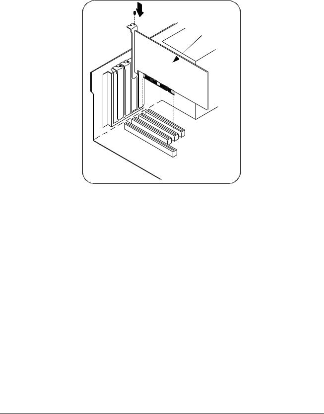
Installing C-size Figure 2-8 shows the installation of C-size instruments.
Instruments
20 Interface Installation and Configuration |
Chapter 2 |
retaining |
seat the module by |
|
pushing in the |
||
screws |
||
extraction levers |
||
|
extraction levers
slide the module |
into the mainframe |
until it plugs into the |
backplane connectors
Figure 2-8. Installing C-size Instruments.
Caution To prevent damage to the VXI instruments, install the instruments when the mainframe is turned off.
A.Insert the instrument into the mainframe by aligning the instrument with the card guides inside the mainframe. Slowly push the instrument into the slot until it seats in the backplane connectors. The front panel of the instrument should be even with the front edges of the mainframe.
B.Tighten the retaining screws on the top and bottom of the module.
Chapter 2 |
Interface Installation and Configuration 21 |

WARNING All instruments within the VXI mainframe are grounded through the mainframe chassis. During installation, tighten the instruments’ retaining screws to secure the instrument to the mainframe and to make the ground connection.
Installing A- and B-size
Instruments
A- and B-size instruments can also be installed in the mainframe. These instruments are installed using a module carrier:
•HP E1403C A/B-size Module Carrier extends the P1 connector on the VXIbus backplane and mounts the (A/B-size) modules flush with C-size modules. This carrier is recommended for Hewlett-Packard B-size, slave-only devices which have the P1 connector.
•HP E1407A A/B Module Carrier extends the P1and P2 connectors on the VXIbus backplane. This carrier is recommended for B-size, slave-only devices which have the P1/P2 connectors.
Figure 2-9 shows the installation of A- and B-size instruments.
22 Interface Installation and Configuration |
Chapter 2 |
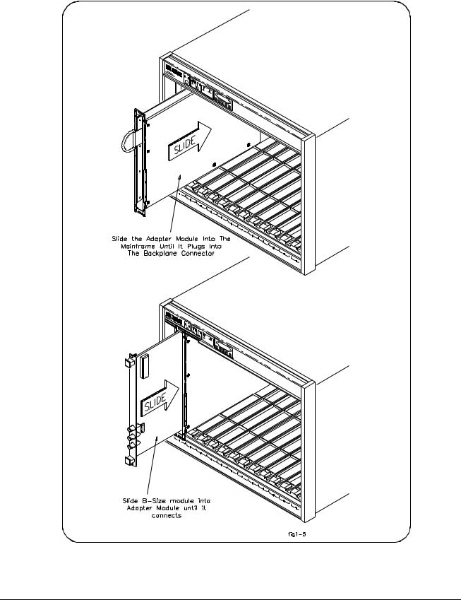
Figure 2-9. Installing A- and B-size VXI Instruments.
Chapter 2 |
Interface Installation and Configuration 23 |

Caution To prevent damage to the VXI instruments, install the instruments when the mainframe is turned off.
A.Install the HP E1403 A/B-size Module Carrier or the HP E1407 A/B-size Module Carrier into the mainframe. This is done by aligning the top and bottom of the carrier with the card guides and slowly pushing the carrier into the mainframe. The front of the carrier should be even with the front edges of the mainframe.
B.Slide the A- or B-size instrument into the carrier until it connects.
C.Tighten the retaining screws on the top and bottom of the instrument.
WARNING All instruments within the VXI mainframe are grounded through the mainframe chassis. During installation, tighten the instruments’ retaining screws to secure the instrument to the mainframe and to make the ground connection.
Step 4: Installing The software required to use the IEEE 1394 interface in a VXI system,
the HP I_O Libraries including the Adaptec® host adapter drivers, is contained on the HP I_O Libraries CD.
Note Refer to Chapter 4: IEEE 1394 Fundamentals and Interface Overview for more information on the HP I_O Libraries and related software.
A.Turn on the PC if you have not already done so. Close all open applications and insert the I_O libraries CD into your PC CD-ROM drive. Inserting the CD automatically activates the installer. If the installer is not activated, select Start / Run and type <drive>:SETUP.EXE. Do not turn on the VXI mainframe.
Note If your PC indicates that new hardware has been found, select “do not
install a driver.” The Adaptec ® host adapter drivers are installed with the I_O libraries installer program.
B.Review the information and license agreements presented at the beginning of the installation process.
C.Continue through the installation process as directed by the installer. Be sure to indicate that you want HP I_O Libraries support for the E8491A interface installed by clicking on the box next to “Install
HP E8491 VXI Components.” Do not configure the interface at this time.
24 Interface Installation and Configuration |
Chapter 2 |
Loading...