


Contents
HP E1368A/69A/70A Modules User’s Manual
Warranty . . . . . . . . . . . . . . . . . . . . . . . . . . . . . . . . . . . . . . . . . . |
5 |
|
WARNINGS . . . . . . . . . . . . . . . . . . . . . . . . . . . . . . . . . . . . . . . . |
6 |
|
Safety Symbols . . . . . . . . . . . . . . . . . . . . . . . . . . . . . . . . . . . . . . |
6 |
|
Declaration of Conformity . . . . . . . . . . . . . . . . . . . . . . . . . . . . . . . . . |
7 |
|
Reader Comment Sheet . . . . . . . . . . . . . . . . . . . . . . . . . . . . . . . . . . |
9 |
|
1. Getting Started with the HP E1368A/69A/70A . . . . . . . . . . . . . . . . . . . . . . . . . |
11 |
|
Using This Chapter . . . . . . . . . . . . . . . . . . . . . . . . . . . . . . . . . . . . |
11 |
|
Microwave Switch Description . . . . . . . . . . . . . . . . . . . . . . . . . . . . . . |
11 |
|
Power Supply Circuit . . . . . . . . . . . . . . . . . . . . . . . . . . . . . . . . . |
13 |
|
HP E1368A Switches . . . . . . . . . . . . . . . . . . . . . . . . . . . . . . . . . |
13 |
|
Instrument Definition . . . . . . . . . . . . . . . . . . . . . . . . . . . . . . . . . . . |
14 |
|
Programming the Microwave Switch . . . . . . . . . . . . . . . . . . . . . . . . . . . |
14 |
|
Card Numbers . . . . . . . . . . . . . . . . . . . . . . . . . . . . . . . . . . . . . |
14 |
|
Channel Numbers . . . . . . . . . . . . . . . . . . . . . . . . . . . . . . . . . . . |
15 |
|
Channel Address . . . . . . . . . . . . . . . . . . . . . . . . . . . . . . . . . . . |
15 |
|
SCPI Command Format Used in This Manual . . . . . . . . . . . . . . . . . . . . |
16 |
|
Initial Operation . . . . . . . . . . . . . . . . . . . . . . . . . . . . . . . . . . . . . . |
16 |
|
2. Configuring the HP E1368A/69A/70A Modules . . . . . . . . . . . . . . . . . . . . . . . . |
17 |
|
Using This Chapter . . . . . . . . . . . . . . . . . . . . . . . . . . . . . . . . . . . . |
17 |
|
Warnings and Cautions . . . . . . . . . . . . . . . . . . . . . . . . . . . . . . . . . . |
17 |
|
Setting the Address Switch . . . . . . . . . . . . . . . . . . . . . . . . . . . . . . . . |
18 |
|
Selecting the Interrupt Priority . . . . . . . . . . . . . . . . . . . . . . . . . . . . . . |
19 |
|
Installing Switches on the HP E1369A . . . . . . . . . . . . . . . . . . . . . . . . . . |
20 |
|
Installing Switches on the Module . . . . . . . . . . . . . . . . . . . . . . . . . . |
20 |
|
Connecting Switches External to the Module . . . . . . . . . . . . . . . . . . . . |
23 |
|
Selecting Switch Power . . . . . . . . . . . . . . . . . . . . . . . . . . . . . . . . |
24 |
|
Connecting Field Wiring . . . . . . . . . . . . . . . . . . . . . . . . . . . . . . . |
25 |
|
Installing a Switch or Attenuator on the HP E1370A Microwave Switch/Attenuator |
|
|
Card . . . . . . . . . . . . . . . . . . . . . . . . . . . . . . . . . . . . . . . . . . . |
26 |
|
Installing a Switch or Attenuator on the Module . . . . |
. . . . . . . . . . . . . . . |
26 |
Connecting Field Wiring . . . . . . . . . . . . . . . . . . . . . . . . . . . . . . . |
28 |
|
3. Using the HP E1368A/69A/70A Modules . . . . . . . . . . . . . . . . . . . . . . . . . . . |
29 |
|
Using This Chapter . . . . . . . . . . . . . . . . . . . . . . . . . . . . . . . . . . . . |
29 |
|
Microwave Switch Commands . . . . . . . . . . . . . . . . . . . . . . . . . . . . . . |
29 |
|
Reset Conditions . . . . . . . . . . . . . . . . . . . . . . . . . . . . . . . . . . . . . . |
30 |
|
Switching Channels . . . . . . . . . . . . . . . . . . . . . . . . . . . . . . . . . . . . |
31 |
|
Example: Single Channel Switching . . . . . . . . . . . . . . . . . . . . . . . . . |
31 |
|
Example: Single Channel Switching using EXTernal POWER . . . . . . . . . . . |
32 |
|
Example: Channel Switching using the E1370A and the 33366K Microwave Switch 33
Example: Multiple Channel Switching using EXTernal POWER . . . . . . . . . . 35
HP E1368A/69A/70A Modules User’s Manual Contents 1

Example: Transfer Switch Using Two 3-Port Switches . . . . . . . . . . . . . . . |
36 |
|
Example: Transfer Switch Using One 5-Port Switch . . . . . . . . . . . . . . . . |
37 |
|
Example: 4 x 1 Multiplexer . . . . . . . . . . . . . . . . . . . . . . . . . . . . . . |
38 |
|
Scanning Channels . . . . . . . . . . . . . . . . . . . . . . . . . . . . . . . . . . . . . |
39 |
|
Example: Scanning Channels . . . . . . . . . . . . . . . . . . . . . . . . . . . . . |
40 |
|
Example: Using the Scan Complete Bit . . . . . . . . . . . . . . . . . . . . . . . |
41 |
|
Recalling and Saving States . . . . . . . . . . . . . . . . . . . . . . . . . . . . . . . . |
43 |
|
Storing States . . . . . . . . . . . . . . . . . . . . . . . . . . . . . . . . . . . . . |
43 |
|
Recalling States . . . . . . . . . . . . . . . . . . . . . . . . . . . . . . . . . . . . |
43 |
|
Detecting Error Conditions . . . . . . . . . . . . . . . . . . . . . . . . . . . . . . . . |
43 |
|
Synchronizing the Microwave Switch . . . . . . . . . . . . . . . . . . . . . . . . . . . |
45 |
|
Synchronizing Instruments . . . . . . . . . . . . . . . . . . . . . . . . . . . . . . |
45 |
|
Querying the Microwave Switch . . . . . . . . . . . . . . . . . . . . . . . . . . . . . |
46 |
|
4. HP E1368A/69A/70A Command Reference . . . . . . . . . . . . . . . . . . . . . . . . . . |
47 |
|
Using This Chapter . . . . . . . . . . . . . . . . . . . . . . . . . . . . . . . . . . . . |
47 |
|
Command Types . . . . . . . . . . . . . . . . . . . . . . . . . . . . . . . . . . . . . . |
47 |
|
Common Command Format . . . . . . . . . . . . . . . . . . . . . . . . . . . . . |
47 |
|
SCPI Command Format . . . . . . . . . . . . . . . . . . . . . . . . . . . . . . . |
47 |
|
Linking Commands . . . . . . . . . . . . . . . . . . . . . . . . . . . . . . . . . . |
49 |
|
SCPI Command Reference . . . . . . . . . . . . . . . . . . . . . . . . . . . . . . . . |
50 |
|
ABORt . . . . . . . . . . . . . . . . . . . . . . . . . . . . . . . . . . . . . . . . . . . |
50 |
|
ARM . . . . . . . . . . . . . . . . . . . . . . . . . . . . . . . . . . . . . . . . . . . . |
51 |
|
:COUNt . . . . . . . . . . . . . . . . . . . . . . . . . . . . . . . . . . . . . . . . |
51 |
|
:COUNt? . . . . . . . . . . . . . . . . . . . . . . . . . . . . . . . . . . . . . . . |
52 |
|
DISPlay . . . . . . . . . . . . . . . . . . . . . . . . . . . . . . . . . . . . . . . . . . |
53 |
|
:MONitor:CARD . . . . . . . . . . . . . . . . . . . . . . . . . . . . . . . . . . . |
53 |
|
:MONitor[:STATe] . . . |
. . . . . . . . . . . . . . . . . . . . . . . . . . . . . . . |
54 |
:MONitor[:STATe]? . . . . . . . . . . . . . . . . . . . . . . . . . . . . . . . . . |
54 |
|
INITiate . . . . . . . . . . . . . . . . . . . . . . . . . . . . . . . . . . . . . . . . . . |
55 |
|
:CONTinuous . . . . . . . . . . . . . . . . . . . . . . . . . . . . . . . . . . . . . |
55 |
|
:CONTinuous? . . . . . . . . . . . . . . . . . . . . . . . . . . . . . . . . . . . . |
56 |
|
[:IMMediate] . . . . . . . . . . . . . . . . . . . . . . . . . . . . . . . . . . . . . |
56 |
|
OUTPut . . . . . . . . . . . . . . . . . . . . . . . . . . . . . . . . . . . . . . . . . . |
57 |
|
[:STATe] . . . . . . . . . . . . . . . . . . . . . . . . . . . . . . . . . . . . . . . |
57 |
|
[:STATe]? . . . . . . . . . . . . . . . . . . . . . . . . . . . . . . . . . . . . . . . |
57 |
|
[ROUTe:] . . . . . . . . . . . . . . . . . . . . . . . . . . . . . . . . . . . . . . . . . |
58 |
|
CLOSe . . . . . . . . . . . . . . . . . . . . . . . . . . . . . . . . . . . . . . . . |
58 |
|
CLOSe? . . . . . . . . . . . . . . . . . . . . . . . . . . . . . . . . . . . . . . . . |
59 |
|
OPEN . . . . . . . . . . . . . . . . . . . . . . . . . . . . . . . . . . . . . . . . . |
59 |
|
OPEN? . . . . . . . . . . . . . . . . . . . . . . . . . . . . . . . . . . . . . . . . |
60 |
|
SCAN . . . . . . . . . . . . . . . . . . . . . . . . . . . . . . . . . . . . . . . . . |
60 |
|
SCAN:MODE . . . . . . . . . . . . . . . . . . . . . . . . . . . . . . . . . . . . . |
61 |
|
SCAN:MODE? . . . . . . . . . . . . . . . . . . . . . . . . . . . . . . . . . . . . |
61 |
|
STATus . . . . . . . . . . . . . . . . . . . . . . . . . . . . . . . . . . . . . . . . . . |
62 |
|
:OPERation:ENABle . . . . . . . . . . . . . . . . . . . . . . . . . . . . . . . . . |
63 |
|
:OPERation:ENABle? . . . . . . . . . . . . . . . . . . . . . . . . . . . . . . . . |
63 |
|
:OPERation[:EVENt]? . . . . . . . . . . . . . . . . . . . . . . . . . . . . . . . . |
64 |
|
2 HP E1368A/69A/70A Modules User’s Manual Contents

SYSTem . . . . . . . . . . . . . . . . . . . . . . . . . . . . . . . . . . . . . . . . . . |
65 |
|
:CDEScription? . . . . . . . . . . . . . . . . . . . . . . . . . . . . . . . . . . . . |
65 |
|
:CPON . . . . . . . . . . . . . . . . . . . . . . . . . . . . . . . . . . . . . . . . |
65 |
|
:CTYPe? . . . . . . . . . . . . . . . . . . . . . . . . . . . . . . . . . . . . . . . |
66 |
|
:ERRor? . . . . . . . . . . . . . . . . . . . . . . . . . . . . . . . . . . . . . . . . |
66 |
|
TRIGger . . . . . . . . . . . . . . . . . . . . . . . . . . . . . . . . . . . . . . . . . . |
67 |
|
[:IMMediate] . . . . . . . . . . . . . . . . . . . . . . . . . . . . . . . . . . . . . |
67 |
|
:SOURce . . . . . . . . . . . . . . . . . . . . . . . . . . . . . . . . . . . . . . . |
67 |
|
:SOURce? . . . . . . . . . . . . . . . . . . . . . . . . . . . . . . . . . . . . . . . |
69 |
|
IEEE 488.2 Common Commands . . . . . . . . . . . . . . . . . . . . . . . . . . . . . |
70 |
|
Command Quick Reference . . . . . . . . . . . . . . . . . . . . . . . . . . . . . . . . |
71 |
|
A. HP E1368A/69A/70A Specifications . . . |
. . . . . . . . . . . . . . . . . . . . . . . . . . . |
73 |
B. HP E1368A/69A/70A Registers . . . . . . . . . . . . . . . . . . . . . . . . . . . . . . . . |
75 |
|
Register Definitions . . . . . . . . . . . . . . . . . . . . . . . . . . . . . . . . . . . . |
75 |
|
Addressing the Registers . . . . . . . . . . . . . . . . . . . . . . . . . . . . . . . . . |
76 |
|
Reading the Registers . . . . . . . . . . . . . . . . . . . . . . . . . . . . . . . . . . . |
76 |
|
ID and Device Type Registers . . . . . . . . . . . . . . . . . . . . . . . . . . . . |
76 |
|
Status/Control Register . . . . . . . . . . . . . . . . . . . . . . . . . . . . . . . . |
77 |
|
Channel Enable Register . . . . . . . . . . . . . . . . . . . . . . . . . . . . . . . |
77 |
|
Writing to the Registers . . . . . . . . . . . . . . . . . . . . . . . . . . . . . . . . . . |
77 |
|
Channel Enable Register . . . . . . . . . . . . . . . . . . . . . . . . . . . . . . . |
77 |
|
C. HP E1368A/69A/70A Error Messages . . . . . . . . . . . . . . . . . . . . . . . . . . . . . |
79 |
|
HP E1368A/69A/70A Modules User’s Manual Contents 3

Notes
4 HP E1368A/69A/70A Modules User’s Manual Contents

Certification
Hewlett-Packard Company certifies that this product met its published specifications at the time of shipment from the factory. HewlettPackard further certifies that its calibration measurements are traceable to the United States National Institute of Standards and Technology (formerly National Bureau of Standards), to the extent allowed by that organization’s calibration facility, and to the calibration facilities of other International Standards Organization members.
Warranty
This Hewlett-Packard product is warranted against defects in materials and workmanship for a period of three years from date of shipment. Duration and conditions of warranty for this product may be superseded when the product is integrated into (becomes a part of) other HP products. During the warranty period, Hewlett-Packard Company will, at its option, either repair or replace products which prove to be defective.
For warranty service or repair, this product must be returned to a service facility designated by Hewlett-Packard (HP). Buyer shall prepay shipping charges to HP and HP shall pay shipping charges to return the product to Buyer. However, Buyer shall pay all shipping charges, duties, and taxes for products returned to HP from another country.
HP warrants that its software and firmware designated by HP for use with a product will execute its programming instructions when properly installed on that product. HP does not warrant that the operation of the product, or software, or firmware will be uninterrupted or error free.
Limitation Of Warranty
The foregoing warranty shall not apply to defects resulting from improper or inadequate maintenance by Buyer, Buyer-supplied products or interfacing, unauthorized modification or misuse, operation outside of the environmental specifications for the product, or improper site preparation or maintenance.
The design and implementation of any circuit on this product is the sole responsibility of the Buyer. HP does not warrant the Buyer’s circuitry or malfunctions of HP products that result from the Buyer’s circuitry. In addition, HP does not warrant any damage that occurs as a result of the Buyer’s circuit or any defects that result from Buyer-supplied products.
NO OTHER WARRANTY IS EXPRESSED OR IMPLIED. HP SPECIFICALLY DISCLAIMS THE IMPLIED WARRANTIES OF MERCHANTABILITY AND FITNESS FOR A PARTICULAR PURPOSE.
Exclusive Remedies
THE REMEDIES PROVIDED HEREIN ARE BUYER’S SOLE AND EXCLUSIVE REMEDIES. HP SHALL NOT BE LIABLE FOR ANY DIRECT, INDIRECT, SPECIAL, INCIDENTAL, OR CONSEQUENTIAL DAMAGES, WHETHER BASED ON CONTRACT, TORT, OR ANY OTHER LEGAL THEORY.
Notice
The information contained in this document is subject to change without notice. HEWLETT-PACKARD (HP) MAKES NO WARRANTY OF ANY KIND WITH REGARD TO THIS MATERIAL, INCLUDING, BUT NOT LIMITED TO, THE IMPLIED WARRANTIES OF MERCHANTABILITY AND FITNESS FOR A PARTICULAR PURPOSE. HP shall not be liable for errors contained herein or for incidental or consequential damages in connection with the furnishing, performance or use of this material. This document contains proprietary information which is protected by copyright. All rights are reserved. No part of this document may be photocopied, reproduced, or translated to another language without the prior written consent of Hewlett-Packard Company. HP assumes no responsibility for the use or reliability of its software on equipment that is not furnished by HP.
Restricted Rights Legend
Use, duplication or disclosure by the U.S. Government is subject to restrictions as set forth in subparagraph (c)(1)(ii) of the Rights in Technical Data and Computer Software clause in DFARS 252.227-7013.
Hewlett-Packard Company
3000 Hanover Street
Palo Alto, California 94304 U.S.A.
Rights for non-DOD U.S. Government Departments and Agencies are as set forth in FAR 52.227-19 (c) (1,2).
HP E1368A, E1369A, E1370A Microwave Switch and Driver Modules User’s Manual
Edition 3
Copyright © 1995 Hewlett-Packard Company. All Rights Reserved.
HP E1368A, E1369A, E1370A Microwave Switch and Driver Modules User’s Manual 5
Documentation History
All Editions and Updates of this manual and their creation date are listed below. The first Edition of the manual is Edition 1. The Edition number increments by 1 whenever the manual is revised. Updates, which are issued between Editions, contain replacement pages to correct or add additional information to the current Edition of the manual. Whenever a new Edition is created, it will contain all of the Update information for the previous Edition. Each new Edition or Update also includes a revised copy of this documentation history page.
Edition 1 . . . . . . . . . . . . . . . . . . . . . . . . . . . . . . . . . . . . . . . . . . . December, 1989
Edition 2 . . . . . . . . . . . . . . . . . . . . . . . . . . . . . . . . . . . . . . . . . . . . . August, 1990
Edition 3 . . . . . . . . . . . . . . . . . . . . . . . . . . . . . . . . . . . . . . . . . . . . . . . June, 1995
Safety Symbols
Instruction manual symbol affixed to product. Indicates that the user must refer to the manual for specific WARNING or CAUTION information to avoid personal injury or damage to the product.
Indicates the field wiring terminal that must |
|
be connected to earth ground before operat- |
|
ing the equipment—protects against electri- |
WARNING |
cal shock in case of fault. |
|
Frame or chassis ground terminal—typi- |
CAUTION |
or |
cally connects to the equipment’s metal |
|
frame. |
|
|
|
|
Alternating current (AC).
Direct current (DC).
Indicates hazardous voltages.
Calls attention to a procedure, practice, or condition that could cause bodily injury or death.
Calls attention to a procedure, practice, or condition that could possibly cause damage to equipment or permanent loss of data.
WARNINGS
The following general safety precautions must be observed during all phases of operation, service, and repair of this product. Failure to comply with these precautions or with specific warnings elsewhere in this manual violates safety standards of design, manufacture, and intended use of the product. Hewlett-Packard Company assumes no liability for the customer’s failure to comply with these requirements.
Ground the equipment: For Safety Class 1 equipment (equipment having a protective earth terminal), an uninterruptible safety earth ground must be provided from the mains power source to the product input wiring terminals or supplied power cable.
DO NOT operate the product in an explosive atmosphere or in the presence of flammable gases or fumes.
For continued protection against fire, replace the line fuse(s) only with fuse(s) of the same voltage and current rating and type. DO NOT use repaired fuses or short-circuited fuse holders.
Keep away from live circuits: Operating personnel must not remove equipment covers or shields. Procedures involving the removal of covers or shields are for use by service-trained personnel only. Under certain conditions, dangerous voltages may exist even with the equipment switched off. To avoid dangerous electrical shock, DO NOT perform procedures involving cover or shield removal unless you are qualified to do so.
DO NOT operate damaged equipment: Whenever it is possible that the safety protection features built into this product have been impaired, either through physical damage, excessive moisture, or any other reason, REMOVE POWER and do not use the product until safe operation can be verified by service-trained personnel. If necessary, return the product to a Hewlett-Packard Sales and Service Office for service and repair to ensure that safety features are maintained.
DO NOT service or adjust alone: Do not attempt internal service or adjustment unless another person, capable of rendering first aid and resuscitation, is present.
DO NOT substitute parts or modify equipment: Because of the danger of introducing additional hazards, do not install substitute parts or perform any unauthorized modification to the product. Return the product to a Hewlett-Packard Sales and Service Office for service and repair to ensure that safety features are maintained.
6 HP E1368A, E1369A, E1370A Microwave Switch and Driver Modules User’s Manual

|
Declaration of Conformity |
|
according to ISO/IEC Guide 22 and EN 45014 |
Manufacturer’s Name: |
Hewlett-Packard Company |
|
Loveland Manufacturing Center |
Manufacturer’s Address: |
815 14th Street S.W. |
|
Loveland, Colorado 80537 |
declares, that the product:
Product Name: HP E1368A Microwave Switch, E1369A Microwave Switch Driver, E1370A Microwave Switch/Attenuator
Model Number: E1368A, E1369A, E1370A
Product Options: |
All |
conforms to the following Product Specifications:
Safety: IEC 1010-1 (1990) Incl. Amend 1 (1992)/EN61010-1 (1993)
CSA C22.2 #1010.1 (1992)
UL 1244
EMC: CISPR 11:1990/EN55011 (1991): Group1 Class A IEC 801-2:1991/EN50082-1 (1992): 4kVCD, 8kVAD IEC 801-3:1984/EN50082-1 (1992): 3 V/m
IEC 801-4:1988/EN50082-1 (1992): 1kV Power Line
.5kV Signal Lines
Supplementary Information: The product herewith complies with the requirements of the Low Voltage Directive 73/23/EEC and the EMC Directive 89/336/EEC and carries the CE-marking accordingly.
Tested in a typical configuration in an HP B-Size VXI mainframe.
April, 1995 |
Jim White, QA Manager |
European contact: Your local Hewlett-Packard Sales and Service Office or Hewlett-Packard GmbH, Department HQ-TRE, Herrenberger Straße 130, D-71034 Böblingen, Germany (FAX +49-7031-14-3143).
HP E1368A, E1369A, E1370A Microwave Switch and Driver Modules User’s Manual 7

Notes
8 HP E1368A, E1369A, E1370A Microwave Switch and Driver Modules User’s Manual

Please fold and tape for mailing
Reader Comment Sheet
HP E1368A, E1369A, E1370A Microwave Switch and Driver Modules User’s Manual
Edition 3
You can help us improve our manuals by sharing your comments and suggestions. In appreciation of your time, we will enter you in a quarterly drawing for a Hewlett-Packard Palmtop Personal Computer (U.S. government employees cannot participate in the drawing).
Your Name |
City, State/Province |
Company Name |
Country |
Job Title |
Zip/Postal Code |
Address |
Telephone Number with Area Code |
Please list the system controller, operating system, programming language, and plug-in modules you are using.
cut along this line
fold here
NO POSTAGE
NECESSARY
IF MAILED
IN THE
UNITED STATES
BUSINESS REPLY MAIL
FIRST CLASS |
|
|
|
|
|
PERMIT NO. 37 |
|
|
|
|
|
|
|
LOVELAND, CO |
||||||||||||||||||||||||
|
|
|
|
|
|
|
|
|
|
|
|
|
|
|
|
|
|
|
|
|
|
|
|
|
|
|
|
|
|
|
|
|
|
|
|
|
|
|
|
|
|
|
|
|
|
|
|
|
|
|
|
|
|
|
|
|
|
|
|
|
|
|
|
|
|
|
|
|
|
|
|
|
|
|
|
|
|
|
|
|
|
|
|
|
|
|
|
|
|
|
|
|
|
|
|
|
|
|
|
|
|
|
|
|
|
|
|
|
|
|
|
|
|
|
|
|
HEWLETT-PACKARD COMPANY
Measurement Systems Division
Learning Products Department
P.O. Box 301
Loveland, CO 80539-9984
|
fold here |
|
|
|
|
|
Please pencil-in one circle for each statement below: |
Disagree |
|
|
|
|
Agree |
|
|
|
|
|||
∙ The documentation is well organized. |
O |
O |
O |
O |
O |
|
∙ Instructions are easy to understand. |
O |
O |
O |
O |
O |
|
∙ The documentation is clearly written. |
O |
O |
O |
O |
O |
|
∙ Examples are clear and useful. |
O |
O |
O |
O |
O |
|
∙ Illustrations are clear and helpful. |
O |
O |
O |
O |
O |
|
∙ The documentation meets my overall expectations. |
O |
O |
O |
O |
O |
|
Please write any comments or suggestions below--be specific.

10 HP E1368A, E1369A, E1370A Microwave Switch and Driver Modules User’s Manual
Chapter 1
Getting Started with the HP E1368A/69A/70A
Using This Chapter
This chapter describes the Microwave Switch modules, and contains information on how to program them using SCPI (Standard Commands for Programmable Instruments) commands. This chapter contains the following:
∙Microwave Switch Description . . . . . . . . . . . . . . . . . . . . . . . Page 11
∙Instrument Definition. . . . . . . . . . . . . . . . . . . . . . . . . . . . . . . Page 14
∙Programming the Microwave Switch . . . . . . . . . . . . . . . . . . Page 14
∙Initial Operation . . . . . . . . . . . . . . . . . . . . . . . . . . . . . . . . . . . Page 16
Microwave Switch Description
All three Microwave Switch modules provide switching of up to five microwave coaxial switches or channels. The difference between the HP E1368A Microwave Switch, the HP E1369A Microwave Switch Driver, and the HP E1370A Microwave Switch/Attenuator Driver modules are described below:
∙The HP E1368A Microwave Switch is a 3-channel, single-pole, double-throw coaxial switch module. The three coaxial switches provided have excellent electrical characteristics for 502 transmission systems operating from DC to 18 GHz. The module panels are numbered 00, 01, and 02 to indicate the channel number of each coaxial switch installed.
∙The HP E1369A Microwave Switch Driver is identical to the HP E1368A, except the coaxial switches are not installed. The module panel has three cutouts and various mounting holes that allow the user to install up to three 3-port, 4-port, or 5-port, 42Vpk drive level coaxial switches. Drive level voltage can be internal (+5 and +12Vdc) or external (42Vpk). The module panel is numbered 00, 01, and 02 to indicate the channel number of each coaxial switch. Channel 03 and 04 are not labeled on the panel. Up to five coaxial switches can be controlled (e.g. three internal, two external; five external; etc) using the 14-pin connector.
∙The HP E1370A Microwave Switch/Attenuator Driver is identical to the HP E1369A, except the module panel and mounting holes have been modified to allow the user to install one Single-pole, Multi-throw Switch or one Step Attenuator. Because of the size of the switches and the attenuators, the module takes up two B-size slots. Drive level voltage can be internal (+5 and +12Vdc) or external (42Vpk). Up to a Single-pole, Six-throw Switch can be mounted on to the assembly or used externally using the 14-pin connector.
Chapter 1 |
Getting Started with the HP E1368A/69A/70A 11 |
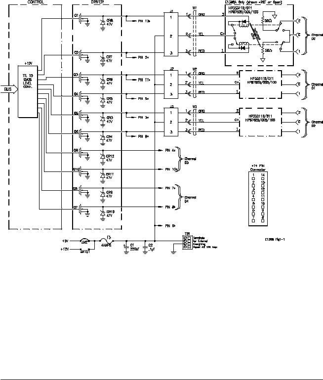
Figure 1-1. HP Microwave Switch Block Diagram
12 Getting Started with the HP E1368A/69A/70A |
Chapter 1 |

Power Supply
Circuit
Power to operate the coaxial switches can be supplied internally or externally, dependent on the type of coaxial switch used.
∙Internal voltages of either +5V or +12V can be selected using jumpers on the board. These voltages are routed through the module from the mainframe backplane.
Note Check mainframe power availability before using internal voltages.
∙External voltages of up to 42Vpk can be connected using the EXTernal POWER terminal block.
Caution
HP E1368A
Switches
MAXIMUM VOLTAGE. The maximum voltage that may be applied to the EXTernal POWER terminal is 42Vpk. Remove the F3 fuse when using external switch power.
MAXIMUM CURRENT. The maximum current that the control circuit can accommodate is 1 amp per switch. Maximum current also depends on the output capacity of the mainframe or power supply used.
The HP E1368A Microwave Switch module contains three HP 33311B Option 011 (8672B Option 005 and 100) microwave Switches:
∙Broad bandwidth (DC - 18 GHz).
∙High isolation (>90 dB to 18 GHz).
∙Excellent repeatability (typically 0.03 dB after 1,000,000 switchings).
∙Internal 50Ω terminations.
These coaxial switches allow +5V coil voltage electrical characteristics (drive voltage) operation instead of the standard +24V. This is necessary since the Microwave Switch module provides only +5V or +12V for driving microwave switches.
These coaxial switches are break-before-make switches controlled by a latching solenoid. Internal coil contacts open and remove coil voltage after a switching operation to minimize the amount of heat dissipated near the switch contacts.
When a coil is energized and a switching operation occurs, a pivot armature in the microwave switch also operates both sets of contacts, either closing the switch or connecting it to the 50Ω termination.
Chapter 1 |
Getting Started with the HP E1368A/69A/70A 13 |

Instrument Definition
HP plug-in modules installed in an HP mainframe or used with an HP command module are treated as independent instruments each having a unique secondary HP-IB address. Each instrument is also assigned a dedicated error queue, input and output buffers, status registers and, if applicable, dedicated mainframe/command module memory space for readings or data. An instrument may be composed of a single plug-in module (such as a counter) or multiple plug-in modules (for a switchbox or scanning voltmeter instrument).
Programming the Microwave Switch
To program the modules using SCPI commands, you must select the controller Module language, interface address, and appropriate commands. See the HP 75000 Series B Installation and Getting Started Guide or the appropriate HP Command Module Manual for interface addressing and controller language information of Microwave Switch modules in a switchbox or scanning voltmeter configuration.
Note This discussion applies to SCPI programming. See Appendix B (Microwave Switch Registers) for details on Microwave Switch modules registers.
Selecting Channels: To address specific channels within a Microwave
Switch module in a switchbox, you must:
∙send the appropriate SCPI command string to the switchbox (e.g., CLOSe, OPEN, etc.). For the Microwave Switch modules, use the CLOSe command to connect the 2-port to the C-port. Use the OPEN command to connect the 1-port to the C-port.
∙ specify the card number (01-99) |
= channel_list |
|
∙ specify the channel number (00-04) |
||
} |
Card Numbers The card number identifies the module within a switchbox. The Microwave Switch card number depends on the switchbox configuration (single-module or multiple-module) set for the switches.
∙Single-module. For a single-module switchbox, the card number is always 01.
∙Multiple-module. For a multiple-module switchbox, the switch module with the lowest logical address is always card number 01. The card number with the next successive logical address is 02, and so on. Figure 1-2 illustrates the card numbers and logical addresses of a typical multiple-module switchbox.
14 Getting Started with the HP E1368A/69A/70A |
Chapter 1 |
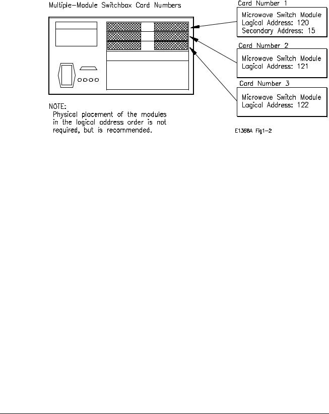
The logical addresses noted in Figure 1-2 apply to modules installed in an HP 75000 Series B Mainframe (HP Model Number E1300/E1301) or in a mainframe with an HP E1405/E1406 Command Module. See the HP 75000 Series B Installation and Getting Started Guide or the appropriate HP Command Module Manual for more information on switchboxes and logical addressing.
Figure 1-2. Card Numbers for Multiple-Module Switchboxes
Channel Numbers The channel number identifies the channel within a module. The Microwave Switch channel number depends on the module (HP E1368A Microwave Switch or HP E1369A Microwave Switch Driver).
∙HP E1368A. Valid channel numbers are 00-04 (channels 03 and 04 are valid but not connected).
∙HP E1369A. Valid channel numbers are 00-04.
∙HP E1370A. Valid channel numbers are 00-04.
Channel Address For the Microwave Switch Modules, the channel address (channel_list) is in the form:
∙(@ccnn) for a single channel
∙(@ccnn, ccnn) for multiple channels
∙(@ccnn:ccnn) for sequential channels
∙(@ccnn:ccnn, ccnn:ccnn) for groups of sequential channels
∙or any combination of the above
where "cc" is the card number and "nn" is the channel number. For example, command string to close channel 02 of card number 1 is:
CLOSe (@0102)
Since "cc" (the card number) must be sent, it becomes part of the channel number. Also, you can ignore leading zeros in the card numbers. Thus, to close channel 02, send "102" instead of "0102". To close the above channel, execute:
CLOSe (@102)
Chapter 1 |
Getting Started with the HP E1368A/69A/70A 15 |

SCPI Command
Format Used in
This Manual
You can send SCPI commands in either short or long form. Refer to Chapter 4 for more information. A long form example is:
CLOSe (@102)
The same command shown without the lower case letters is the short form. The command then becomes:
CLOS (@102)
Some commands in this manual are shown with brackets ([ ]). These are implied or optional commands that you do not have to execute. For example, the ROUTe command is an implied command and is shown in this manual as:
[ROUT:]CLOS (@102)
Thus, to execute these commands, simply enter:
CLOS (@102)
Initial Operation
Use the following program example to verify initial Microwave Switch operation by closing a channel and querying channel closure. The example first resets the switchbox and then closes channel 02 of a single Microwave Switch module (card number 1) in the switchbox. The program next queries the channel closure state. A returned "1" shows that the command to close the channel has been sent to the switchbox. A returned "0" shows that the command to close the channel has not been sent to the switchbox.
The computer used in the example is an HP Series 200/300 computer with HP BASIC as the program language. The computer interfaces to the mainframe using the Hewlett-Packard Interface Bus (HP-IB).* The HP-IB interface select code is 7, the HP-IB primary address is 09, and the HP-IB secondary address is 15. Refer to the HP 75000 Series B Installation and Getting Started Guide for addressing information.
Example: Reset the switchbox and close channel 02.
10 OUTPUT 70915;"*RST" |
!Resets the module; opens all |
|
channels. |
20 OUTPUT 70915;"CLOS (@102)" |
!Close channel 02. |
30 OUTPUT 70915;"CLOS? (@102)" |
!Query channel 02. |
40 ENTER 70915;Value |
!Enter results into value. |
50 PRINT Value |
!Display results (should return |
|
"1"). |
60 END |
!Terminate program. |
* HP-IB is Hewlett-Packard’s implementation of IEEE Std 488.1-1984
16 Getting Started with the HP E1368A/69A/70A |
Chapter 1 |

Chapter 2
Configuring the HP E1368A/69A/70A
Modules
Using This Chapter
This chapter shows how to connect external wiring to the Microwave
Switch Modules connectors, and how to configure the module for operation.
∙ Setting the Address Switch . . . . . . . . . . . . . . . . . . . . . . . . . . Page 18 ∙ Selecting the Interrupt Priority . . . . . . . . . . . . . . . . . . . . . . . Page 19 ∙ Installing Switches on the HP E1369A . . . . . . . . . . . . . . . . . Page 20 ∙ Installing a Switch or Attenuator on the
HP E1370A. . . . . . . . . . . . . . . . . . . . . . . . . . . . . . . . . . . . . Page 26
Warnings and Cautions
Warning SHOCK HAZARD. Only service-trained personnel who are aware of the hazards involved should install, remove, or configure the Microwave Switch modules. Before you remove any installed module, disconnect AC power from the mainframe and from other modules that may be connected to the Microwave Switch.
Caution MAXIMUM POWER. The maximum power that may be applied to any SMA input connector is 1 W (CW). The maximum voltage that may be applied to the EXTERNAL B+ terminal is 42Vpk.
CONNECTING +5V/+12V. For the Microwave Switch, the mainframe backplane +5V is fused at 4A, and the +12V line at 4A. The total current drawn by all coaxial switches connected to the Microwave Switch module must not exceed the fuse rating of the supplies (mainframe and/or external) used.
STATIC ELECTRICITY. Static electricity is a major cause of component failure. To prevent damage to the electrical components in the Microwave Switch modules, observe anti-static techniques whenever removing a module from the mainframe or whenever working on a module.
Chapter 2 |
Configuring the HP E1368A/69A/70A Modules 17 |
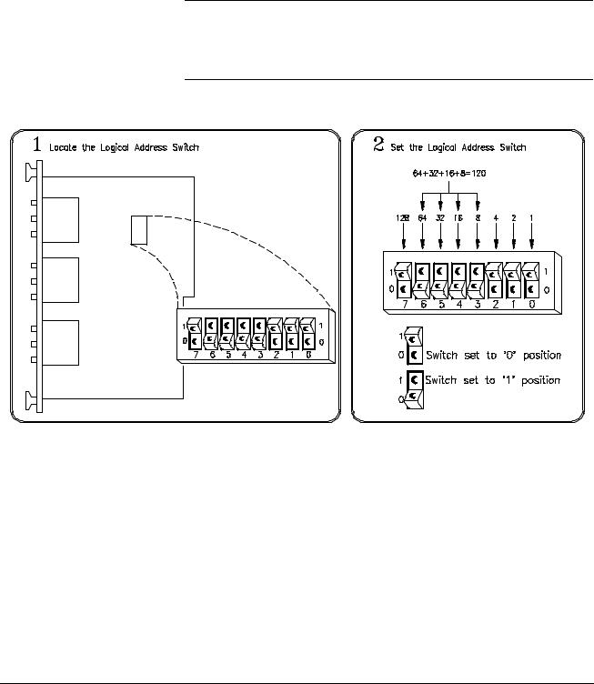
Setting the Address Switch
The logical address switch (LADDR) factory setting is 120. You may have changed the setting during module installation. Valid address values are from 0 to 255. If the Microwave Switch modules are used in a HP E1300/E1301 Mainframe, refer to the HP 75000 Series B System Installation and Getting Started Guide for addressing information. Otherwise, use Figure 2-1 to change the setting.
Note The address switch selected value must be a multiple of 8 if the module is the first module in a "switchbox" used in a VXIbus mainframe, and being instructed by SCPI commands.
Figure 2-1. Logical Address Selection
18 Configuring the HP E1368A/69A/70A Modules |
Chapter 2 |
Selecting the Interrupt Priority
The Microwave Switch modules generate interrupts after a channel has been closed or opened. These interrupts are sent to, and acknowledgments are received from, the slot 0 module via the VXIbus backplane interrupt lines.
For most applications where the Microwave Switch modules are installed in an HP 75000 Series B or Series C mainframe, these jumpers do not have to be moved. This is because the VXIbus interrupt lines have the same priority and interrupt priority is established by installing modules in slots numerically closest to the slot 0 module. Thus, slot 1 (internal to the Series B mainframe) has a higher priority than slot 2 (also internal), slot 2 has a higher priority than slot 3, etc.
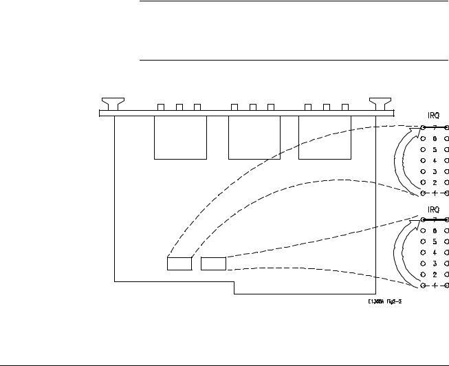
Refer to Figure 2-2 to change the interrupt priority. You can select seven different interrupt priority levels. Level 1 is the lowest priority and Level 7 is the highest priority. The Module’s factory setting is Level 1. To change, clip out and remove two jumpers from the old priority location. Install and solder two new jumpers in the new priority location (Figure 2-2 shows a priority change from 1 to 7).
Note Both jumper locations must have the same interrupt priority level jumper installed. Changing the priority level jumpers is not recommended. Do not change unless specifically instructed to do so.
NOTE:
In this example, the priority jumpers are moved from position 1 to position 7 (lowest priority to highest priority).
Figure 2-2. Interrupt Priority Selection
Chapter 2 |
Configuring the HP E1368A/69A/70A Modules 19 |

Installing Switches on the HP E1369A
Installing Switches
on the Module
Note
Because the HP E1369A Microwave Switch modules do not have Microwave Switches installed by the factory, it is necessary to install or connect switches before operating. Determine the number of switches, and whether the switches are to be installed on, or connected to, the module and proceed as instructed below.
Installation described for up to three coaxial switches (channels 00-02) is below. Figure 2-3 shows the wiring diagram and mounting hole centers for each switch installed.
HP SWITCHES. The following 5V HP 333XX series and HP 876X series switches will function in the HP E1369A Microwave Switch module.
The corresponding HP 876X and 333XX series switches shown in the table below are electrically and physically identical. The HP 8761, 8766 (33363), 8767 (33364),8768 (33365),8769 (33366) series coaxial switches will not function in the HP E1369A Microwave Switch module because the switch coils are not split (separate for each contact).
HP Part Number |
Frequency |
Characteristic |
Ports |
Internal 50Ω |
Auto Coil |
MTG |
|
|
Impedance |
|
Termination |
Interrupt |
Hole |
|
|
|
|
|
|
|
|
|
|
|
|
|
|
33311B/011 or 8762B/005/100 |
DC to 18 GHz |
50Ω |
3 |
All ports |
Yes |
C |
33311C/011 or 8762C/005/100 |
DC to 26.5 GHz |
50Ω |
3 |
All ports |
Yes |
C |
33312B/011 or 8763B/005/100 |
DC to 18 GHz |
50Ω |
4 |
One port |
Yes |
D |
33312C/011 or 8763C/005/100 |
DC to 26.5 GHz |
50Ω |
4 |
One port |
Yes |
D |
33313B/011 or 8764B/005/100 |
DC to 18 GHz |
50Ω |
5 |
No ports |
Yes |
D |
33313C/011 or 8764C/005/100 |
DC to 26.5 GHz |
50Ω |
5 |
No ports |
Yes |
D |
33314A/011 or 8765A/005/100 |
DC to 4 GHz |
50Ω |
3 |
No ports |
No |
B |
33314B/011 or 8765B/005/100 |
DC to 20 GHz |
50Ω |
3 |
No ports |
No |
B |
33314C/011 or 8765C/005/100 |
DC to 26.5 GHz |
50Ω |
3 |
No ports |
No |
B |
|
|
|
|
|
|
|
NON-HP SWITCHES. K&L Microwave Inc., Dynatech Microwave Technology Inc., and RLC Electronics Inc. currently manufacture split coil coaxial switches that will physically mount in the HP E1369A Microwave Switch module rear panel. All switches mount using the "A" hole centers (see Figure 2-3). When selecting switches, refer to the diagram shown in Figure 1-1 to verify that the switch will electrically function in the HP E1369A Microwave Switch module. Remember, switches must have split coil operation with 42V maximum drive level.
Caution The maximum current that the control circuit can accommodate is 1 amp per switch. Maximum current also depends on the output capacity of the mainframe or power supply used.
20 Configuring the HP E1368A/69A/70A Modules |
Chapter 2 |
After selecting the coaxial switch, install as follows:
1.Position the coaxial switch behind the channel 00 panel cut-out. Secure to rear panel using two M2.5 x .45 metric screws
(P/N 0515-1373).
2.Route the 3-wire cable (P/N E1368-61601) from J1 to the coaxial switch terminals. Solder the "RED" wire to pin 1. Solder the "YEL" wire to pin C. Solder the "ORN" wire to pin 2.
Note On the HP 33314 (8765) series switches, it is necessary to jumper the two C terminals so that both connect to the "YEL" wire.
3.Repeat steps 1 and 2 with remaining coaxial switches. The channel 01 switch connects to J2 connector, and channel 02 connects to J3.
Caution Do not leave an unused 3-wire cable installed in J1, J2, or J3 if a coaxial switch is not installed. The center conductor of all three connectors is connected to the switch operating voltage at all times. Contact of this conductor to ground may cause the fuse to open, or damage to the power supply or module.
4.Route the 3-wire cables behind the coaxial switches as not to catch or snag on any objects during module installation in the mainframe or control module (see Figure 2-3).
5.Select correct switch operating voltages (see “ Sele cting Switch Power” later in this chapter).
Chapter 2 |
Configuring the HP E1368A/69A/70A Modules 21 |

Figure 2-3. Microwave Switch Installation
22 Configuring the HP E1368A/69A/70A Modules |
Chapter 2 |
Connecting
Switches External
to the Module
Caution
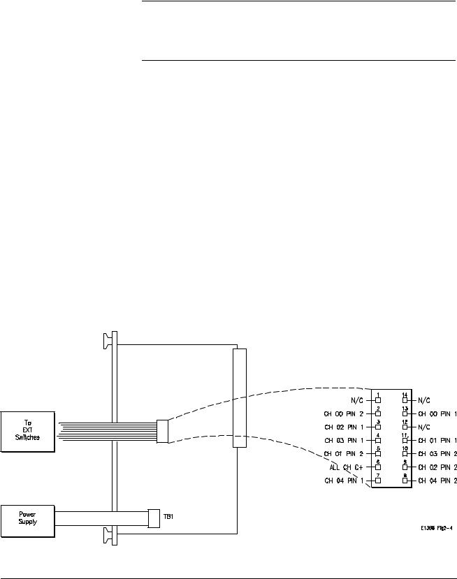
Connection of up to five coaxial switches (channels 00-04) is described below. Figure 2-4 shows the wiring diagram for each switch connected.
The maximum current that the control circuit can accommodate is 1 amp per switch. Maximum current also depends on the output capacity of the mainframe or power supply used.
After selecting the coaxial switches, connect to the 14-pin connector as follows:
1.Route an 11-wire cable (not-supplied) from the 14-pin connector on the Microwave Switch module to the switch location. Route the wires through the panel holes as not to catch or snag on any objects during module installation in the mainframe or control module.
2.Connect all C+ terminals on all the coaxial switches to pin 6.
3.Connect CH00 through CH04 switch terminals as required.
CH00 1 terminal to pin 13, and the 2 terminal to pin 2.
CH01 1 terminal to pin 11, and the 2 terminal to pin 5.
CH02 1 terminal to pin 3, and the 2 terminal to pin 9.
CH03 1 terminal to pin 4, and the 2 terminal to pin 10.
CH04 1 terminal to pin 7, and the 2 terminal to pin 8.
4.Select correct switch operating voltages (see “ Sele cting Switch Power” later in this chapter).
Figure 2-4. Microwave Switch Connection
Chapter 2 |
Configuring the HP E1368A/69A/70A Modules 23 |

Selecting Switch
Power
After the coaxial switches have been installed (refer to “ Installing Switches on the HP E1369A” earlier in this chapter), the correct operating voltage must be selected. See installed switch specifications.
The Microwave Switch modules are capable of providing +5V (set at factory) or +12V using the mainframe power supply, or external voltages of up to 42Vpk can be connected. Determine the required operating voltage and proceed as instructed below. Refer to Figure 2-5 as required.
Caution MAXIMUM CURRENT. The maximum current that the control circuit can accommodate is 1 amp per switch. Maximum current also depends on the output capacity of the mainframe or power supply used.
Internal Power Verify that the F3 fuse (P/N 2110-0712) is installed. Position jumpers as instructed:
∙For 5V, jumper JM2 installed, and jumper JM151 removed.
∙For 12V, jumper JM151 installed, and jumper JM2 removed.
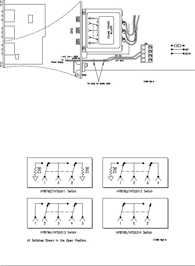
External Power Verify that the F3 fuse (P/N 2110-0712) is removed (unsolder if necessary). Connect the positive lead to EXT B+ on TB1, and the negative lead to EXT GND on TB1. Connect leads to external power supply. Observe polarity.
Caution MAXIMUM VOLTAGE. The maximum voltage that may be applied to the EXTernal POWER terminal is 42Vpk.
∙Maximum wire size is No. 16 AWG. Wire ends should be stripped 6 mm (~ 0.25 in.) and tinned to prevent single strands from shorting adjacent terminals.
∙It is recommended that each channel wire be identified (color coded or marked) as the connection is not visible when the Microwave Switch module is installed.
∙Verify that wires make good connections on screw terminals.
24 Configuring the HP E1368A/69A/70A Modules |
Chapter 2 |
Connecting Field
Wiring
Figure 2-5. Selecting Switch Voltage
Figure 2-6 shows the internal switch diagram for the various HP 3-port, 4-port, and 5-port coaxial switches. All switches are shown in the "OPEN" position. To minimize loss at high frequencies, use the following guidelines when making connections.
Cabling Guidelines For frequencies to 18 GHz, use a good quality flexible type cable and SMA connectors. For frequencies 18 GHz, use semi-rigid type cable and APC 3.5 connectors.
Figure 2-6. Switch Configurations
Chapter 2 |
Configuring the HP E1368A/69A/70A Modules 25 |

Installing a Switch or Attenuator on the HP E1370A Microwave Switch/Attenuator Card
Installing a Switch
or Attenuator on
the Module
Because the HP E1370A Microwave Switch/Attenuator modules do not have a Microwave Switch of Attenuator installed by the factory, it is necessary to install or connect a switch or attenuator before operating. Determine whether the switch or attenuator is to be installed on, or connected to, the module and proceed as instructed below.
Installation of a Microwave Switch of Attenuator is described below. Figure 2-7 shows the wiring diagram and mounting hole centers for the switch of attenuator installed.
HP SWITCHES. The following 5V HP 3336xx series switches will function in the HP E1370A Microwave Switch/Attenuator module.
HP Part Number |
Frequency |
Ports |
|
|
|
|
|
|
33363K |
DC to 26.5GHz |
Single-Pole, three-throw |
33364K |
DC to 26.5GHz |
Single-Pole, four-throw |
33365K |
DC to 26.5GHz |
Single-Pole, five-throw |
33366K |
DC to 26.5GHz |
Single-Pole, six-throw |
|
|
|
|
|
|
Order all of the above with Option 011 (5 volt solenoid assembly) and Option 008 (8 inch ribbon cable).
HP ATTENUATORS. The following 5V HP 3332X Step Attenuators will function in the HP E1370A Microwave Switch/Attenuator module.
HP Part |
Frequency |
Attenuation |
Attenuation Step |
Number |
|
|
Size |
|
|
|
|
|
|
|
|
33320G |
DC to 4 GHz |
0 - 11 dB |
1 dB |
33320H |
DC to 18 GHz |
0 - 11 dB |
1 dB |
33321G |
DC to 4 GHz |
0 - 70 dB |
10 dB |
33321H |
DC to 18 GHz |
0 - 70 dB |
10 dB |
33322G |
DC to 4 GHz |
0 - 110 dB |
10 dB |
33322H |
DC to 18 GHz |
0 - 110 dB |
10 dB |
33323K |
DC to 26.5 GHz |
0 - 90 dB |
10 dB |
|
|
|
|
|
|
|
|
Order all of the above with Option 011 (5 volt solenoid operation) and Option 008 (8 inch ribbon cable).
26 Configuring the HP E1368A/69A/70A Modules |
Chapter 2 |
 Loading...