


 Loading...
HP StorageWorks
e1200-320 4Gb Fibre Channel Interface Card user and service guide
*AD577-96004*
AD577-96004
Part number: AD577-96004
First edition: May 2006
Legal and notice information
© Copyright 2006 Hewlett-Packard Development Company, L.P.
Hewlett-Packard Company makes no warranty of any kind with regard to this material, including, but not limited to, the implied warranties of merchantability and fitness for a particular purpose. Hewlett-Packard shall not be liable for errors contained herein or for incidental or consequential damages in connection with the furnishing, performance, or use of this material.
This document contains proprietary information, which is protected by copyright. No part of this document may be photocopied, reproduced, or translated into another language without the prior written consent of Hewlett-Packard. The information is provided “as is” without warranty of any kind and is subject to change without notice. The only warranties for HP products and services are set forth in the express warranty statements accompanying such products and services. Nothing herein should be construed as constituting an additional warranty. HP shall not be liable for technical or editorial errors or omissions contained herein.
Adobe® and Acrobat® are trademarks of Adobe Systems Incorporated.
Intel and Itanium are trademarks or registered trademarks of Intel Corporation or its subsidiaries in the United States and other countries. Microsoft, Windows, Windows NT, and Windows XP are U.S. registered trademarks of Microsoft Corporation.
Oracle® is a registered U.S. trademark of Oracle Corporation, Redwood City, California. UNIX® is a registered trademark of The Open Group.
e1200-320 4Gb Fibre Channel Interface Card user and service guide

Contents
About this guide. . . . . . . . . . . . . . . . . . . . . . . . . . . . . . . . . . . . . . . . . . . . . . . . . . . . . . . 7
Intended audience . . . . . . . . . . . . . . . . . . . . . . . . . . . . . . . . . . . . . . . . . . . . . . . . . . . . . . . . . . . . . . . 7 Related documentation . . . . . . . . . . . . . . . . . . . . . . . . . . . . . . . . . . . . . . . . . . . . . . . . . . . . . . . . . . . . 7 Document conventions and symbols . . . . . . . . . . . . . . . . . . . . . . . . . . . . . . . . . . . . . . . . . . . . . . . . . . . 7 HP technical support . . . . . . . . . . . . . . . . . . . . . . . . . . . . . . . . . . . . . . . . . . . . . . . . . . . . . . . . . . . . . . 8 HP-authorized reseller. . . . . . . . . . . . . . . . . . . . . . . . . . . . . . . . . . . . . . . . . . . . . . . . . . . . . . . . . . . 8 Helpful web sites . . . . . . . . . . . . . . . . . . . . . . . . . . . . . . . . . . . . . . . . . . . . . . . . . . . . . . . . . . . . . . 8
1 Introduction . . . . . . . . . . . . . . . . . . . . . . . . . . . . . . . . . . . . . . . . . . . . . . . . . . . . . . . . 9
Operation indicators . . . . . . . . . . . . . . . . . . . . . . . . . . . . . . . . . . . . . . . . . . . . . . . . . . . . . . . . . . . . . 10 How the HP e1200-320 4Gb FC Interface Card works . . . . . . . . . . . . . . . . . . . . . . . . . . . . . . . . . . . . . 11 Processing SCSI information. . . . . . . . . . . . . . . . . . . . . . . . . . . . . . . . . . . . . . . . . . . . . . . . . . . . . . . . 11 HP e1200-320 4Gb FC Interface Card features . . . . . . . . . . . . . . . . . . . . . . . . . . . . . . . . . . . . . . . . . . 11 Fibre Channel features . . . . . . . . . . . . . . . . . . . . . . . . . . . . . . . . . . . . . . . . . . . . . . . . . . . . . . . . . 11 SCSI bus features. . . . . . . . . . . . . . . . . . . . . . . . . . . . . . . . . . . . . . . . . . . . . . . . . . . . . . . . . . . . . 11 Management features. . . . . . . . . . . . . . . . . . . . . . . . . . . . . . . . . . . . . . . . . . . . . . . . . . . . . . . . . . 11 External indicators . . . . . . . . . . . . . . . . . . . . . . . . . . . . . . . . . . . . . . . . . . . . . . . . . . . . . . . . . . . . 12 Operating environment. . . . . . . . . . . . . . . . . . . . . . . . . . . . . . . . . . . . . . . . . . . . . . . . . . . . . . . . . 12 Non-operating environment (i.e. for unit storage) . . . . . . . . . . . . . . . . . . . . . . . . . . . . . . . . . . . . . . . 12 HP e1200-320 4Gb Interface Card benefits . . . . . . . . . . . . . . . . . . . . . . . . . . . . . . . . . . . . . . . . . . . . 12
2 Installation, cabling, and setup. . . . . . . . . . . . . . . . . . . . . . . . . . . . . . . . . . . . . . . . . . 13
Installing the HP e1200-320 4Gb Interface Card . . . . . . . . . . . . . . . . . . . . . . . . . . . . . . . . . . . . . . . . . 13 Identifying product components . . . . . . . . . . . . . . . . . . . . . . . . . . . . . . . . . . . . . . . . . . . . . . . . . . . 13 Removal and installation. . . . . . . . . . . . . . . . . . . . . . . . . . . . . . . . . . . . . . . . . . . . . . . . . . . . . . . . 14 Removing an existing interface card. . . . . . . . . . . . . . . . . . . . . . . . . . . . . . . . . . . . . . . . . . . . . . . . 15 Installing a new card . . . . . . . . . . . . . . . . . . . . . . . . . . . . . . . . . . . . . . . . . . . . . . . . . . . . . . . . . . 16
Interfaces and connections. . . . . . . . . . . . . . . . . . . . . . . . . . . . . . . . . . . . . . . . . . . . . . . . . . . . . . . . . 20 Fibre Channel connections . . . . . . . . . . . . . . . . . . . . . . . . . . . . . . . . . . . . . . . . . . . . . . . . . . . . . . 20 SCSI connection . . . . . . . . . . . . . . . . . . . . . . . . . . . . . . . . . . . . . . . . . . . . . . . . . . . . . . . . . . . . . 20 Ethernet connection . . . . . . . . . . . . . . . . . . . . . . . . . . . . . . . . . . . . . . . . . . . . . . . . . . . . . . . . . . . 21 Serial port connection . . . . . . . . . . . . . . . . . . . . . . . . . . . . . . . . . . . . . . . . . . . . . . . . . . . . . . . . . 21
Autobaud feature . . . . . . . . . . . . . . . . . . . . . . . . . . . . . . . . . . . . . . . . . . . . . . . . . . . . . . . . . . 21 Setting up serial port communications . . . . . . . . . . . . . . . . . . . . . . . . . . . . . . . . . . . . . . . . . . . . . . . . . 22
3 Device management . . . . . . . . . . . . . . . . . . . . . . . . . . . . . . . . . . . . . . . . . . . . . . . . . 23
SCSI bus configuration . . . . . . . . . . . . . . . . . . . . . . . . . . . . . . . . . . . . . . . . . . . . . . . . . . . . . . . . . . . 23 FC port configuration . . . . . . . . . . . . . . . . . . . . . . . . . . . . . . . . . . . . . . . . . . . . . . . . . . . . . . . . . . . . 23 FC arbitrated loop addressing . . . . . . . . . . . . . . . . . . . . . . . . . . . . . . . . . . . . . . . . . . . . . . . . . . . . . . 23 Soft addressing . . . . . . . . . . . . . . . . . . . . . . . . . . . . . . . . . . . . . . . . . . . . . . . . . . . . . . . . . . . . . . 23 Hard addressing . . . . . . . . . . . . . . . . . . . . . . . . . . . . . . . . . . . . . . . . . . . . . . . . . . . . . . . . . . . . . 23 FC switched fabric addressing . . . . . . . . . . . . . . . . . . . . . . . . . . . . . . . . . . . . . . . . . . . . . . . . . . . . . . 23 Discovery . . . . . . . . . . . . . . . . . . . . . . . . . . . . . . . . . . . . . . . . . . . . . . . . . . . . . . . . . . . . . . . . . . . . 24 Host bus adapter configuration . . . . . . . . . . . . . . . . . . . . . . . . . . . . . . . . . . . . . . . . . . . . . . . . . . . . . 24 Logical unit management . . . . . . . . . . . . . . . . . . . . . . . . . . . . . . . . . . . . . . . . . . . . . . . . . . . . . . . . . . 24
4 Interface card management . . . . . . . . . . . . . . . . . . . . . . . . . . . . . . . . . . . . . . . . . . . . 27
Configuration methods . . . . . . . . . . . . . . . . . . . . . . . . . . . . . . . . . . . . . . . . . . . . . . . . . . . . . . . . . . . 27 Serial port management access . . . . . . . . . . . . . . . . . . . . . . . . . . . . . . . . . . . . . . . . . . . . . . . . . . . 27 Out-of-band Ethernet management access . . . . . . . . . . . . . . . . . . . . . . . . . . . . . . . . . . . . . . . . . . . . 27 Command Line Interface . . . . . . . . . . . . . . . . . . . . . . . . . . . . . . . . . . . . . . . . . . . . . . . . . . . . . 28 Visual manager . . . . . . . . . . . . . . . . . . . . . . . . . . . . . . . . . . . . . . . . . . . . . . . . . . . . . . . . . . . 28 FTP . . . . . . . . . . . . . . . . . . . . . . . . . . . . . . . . . . . . . . . . . . . . . . . . . . . . . . . . . . . . . . . . . . . . 29 Inband SCSI-3 commands. . . . . . . . . . . . . . . . . . . . . . . . . . . . . . . . . . . . . . . . . . . . . . . . . . . . . . . 29
e1200-320 4Gb Fibre Channel Interface Card user and service guide |
3 |
5 Visual manager user interface. . . . . . . . . . . . . . . . . . . . . . . . . . . . . . . . . . . . . . . . . . 31
Visual manager access . . . . . . . . . . . . . . . . . . . . . . . . . . . . . . . . . . . . . . . . . . . . . . . . . . . . . . . . . . . 31 Main menu . . . . . . . . . . . . . . . . . . . . . . . . . . . . . . . . . . . . . . . . . . . . . . . . . . . . . . . . . . . . . . . . . . . 32 Visual Manager menu structure . . . . . . . . . . . . . . . . . . . . . . . . . . . . . . . . . . . . . . . . . . . . . . . . . . . 32 Home page . . . . . . . . . . . . . . . . . . . . . . . . . . . . . . . . . . . . . . . . . . . . . . . . . . . . . . . . . . . . . . . . 33 System menu . . . . . . . . . . . . . . . . . . . . . . . . . . . . . . . . . . . . . . . . . . . . . . . . . . . . . . . . . . . . . . . . . . 34 Serial configuration . . . . . . . . . . . . . . . . . . . . . . . . . . . . . . . . . . . . . . . . . . . . . . . . . . . . . . . . . . . 35 Network configuration . . . . . . . . . . . . . . . . . . . . . . . . . . . . . . . . . . . . . . . . . . . . . . . . . . . . . . . . . 36 Active fabric configuration . . . . . . . . . . . . . . . . . . . . . . . . . . . . . . . . . . . . . . . . . . . . . . . . . . . . . . 37 User. . . . . . . . . . . . . . . . . . . . . . . . . . . . . . . . . . . . . . . . . . . . . . . . . . . . . . . . . . . . . . . . . . . . . . 38 Real-Time Clock configuration . . . . . . . . . . . . . . . . . . . . . . . . . . . . . . . . . . . . . . . . . . . . . . . . . . . . 39 Reset menu . . . . . . . . . . . . . . . . . . . . . . . . . . . . . . . . . . . . . . . . . . . . . . . . . . . . . . . . . . . . . . . . . 40 Ports menu. . . . . . . . . . . . . . . . . . . . . . . . . . . . . . . . . . . . . . . . . . . . . . . . . . . . . . . . . . . . . . . . . . . . 41 Fibre Channel port configuration . . . . . . . . . . . . . . . . . . . . . . . . . . . . . . . . . . . . . . . . . . . . . . . . . . 42 SCSI bus configuration . . . . . . . . . . . . . . . . . . . . . . . . . . . . . . . . . . . . . . . . . . . . . . . . . . . . . . . . . 43 Discovery menu . . . . . . . . . . . . . . . . . . . . . . . . . . . . . . . . . . . . . . . . . . . . . . . . . . . . . . . . . . . . . . . . 44 Mapping menu . . . . . . . . . . . . . . . . . . . . . . . . . . . . . . . . . . . . . . . . . . . . . . . . . . . . . . . . . . . . . . . . 46 Fibre Channel mapping tasks . . . . . . . . . . . . . . . . . . . . . . . . . . . . . . . . . . . . . . . . . . . . . . . . . . . . 46 Viewing and changing Fibre Channel map information . . . . . . . . . . . . . . . . . . . . . . . . . . . . . . . . 47 Viewing and changing Fibre Channel host information . . . . . . . . . . . . . . . . . . . . . . . . . . . . . . . . 47 Statistics menu . . . . . . . . . . . . . . . . . . . . . . . . . . . . . . . . . . . . . . . . . . . . . . . . . . . . . . . . . . . . . . . . . 48 Utilities menu . . . . . . . . . . . . . . . . . . . . . . . . . . . . . . . . . . . . . . . . . . . . . . . . . . . . . . . . . . . . . . . . . . 49 FTP utility access . . . . . . . . . . . . . . . . . . . . . . . . . . . . . . . . . . . . . . . . . . . . . . . . . . . . . . . . . . . . . 50 Trace settings configuration. . . . . . . . . . . . . . . . . . . . . . . . . . . . . . . . . . . . . . . . . . . . . . . . . . . . . . 51 Current, previous, and last assert trace displays . . . . . . . . . . . . . . . . . . . . . . . . . . . . . . . . . . . . . . . 52 Clear current trace buffer or assert trace buffer . . . . . . . . . . . . . . . . . . . . . . . . . . . . . . . . . . . . . . . . 52 Event log settings . . . . . . . . . . . . . . . . . . . . . . . . . . . . . . . . . . . . . . . . . . . . . . . . . . . . . . . . . . . . . 52 Event log display . . . . . . . . . . . . . . . . . . . . . . . . . . . . . . . . . . . . . . . . . . . . . . . . . . . . . . . . . . . . . 53 Clear event log . . . . . . . . . . . . . . . . . . . . . . . . . . . . . . . . . . . . . . . . . . . . . . . . . . . . . . . . . . . . . . 54 SCSI command tracking . . . . . . . . . . . . . . . . . . . . . . . . . . . . . . . . . . . . . . . . . . . . . . . . . . . . . . . . 54 Report menu . . . . . . . . . . . . . . . . . . . . . . . . . . . . . . . . . . . . . . . . . . . . . . . . . . . . . . . . . . . . . . . . . . 55 Reboot option . . . . . . . . . . . . . . . . . . . . . . . . . . . . . . . . . . . . . . . . . . . . . . . . . . . . . . . . . . . . . . . . . 56
6 Using the Command Line Interface . . . . . . . . . . . . . . . . . . . . . . . . . . . . . . . . . . . . . . |
57 |
Power-up messages. . . . . . . . . . . . . . . . . . . . . . . . . . . . . . . . . . . . . . . . . . . . . . . . . . . . . . . . . . . . . . 57 Perform configuration . . . . . . . . . . . . . . . . . . . . . . . . . . . . . . . . . . . . . . . . . . . . . . . . . . . . . . . . . . . . 58 Baud rate configuration . . . . . . . . . . . . . . . . . . . . . . . . . . . . . . . . . . . . . . . . . . . . . . . . . . . . . . . . 59 Ethernet configuration . . . . . . . . . . . . . . . . . . . . . . . . . . . . . . . . . . . . . . . . . . . . . . . . . . . . . . . . . 60 Fibre Channel configuration . . . . . . . . . . . . . . . . . . . . . . . . . . . . . . . . . . . . . . . . . . . . . . . . . . . . . 62 Parallel SCSI configuration . . . . . . . . . . . . . . . . . . . . . . . . . . . . . . . . . . . . . . . . . . . . . . . . . . . . . . 65 SCSI initiator menu . . . . . . . . . . . . . . . . . . . . . . . . . . . . . . . . . . . . . . . . . . . . . . . . . . . . . . . . . 66 Maximum SCSI bus speed menu. . . . . . . . . . . . . . . . . . . . . . . . . . . . . . . . . . . . . . . . . . . . . . . . 67 Device mapping . . . . . . . . . . . . . . . . . . . . . . . . . . . . . . . . . . . . . . . . . . . . . . . . . . . . . . . . . . . . . 68 Adding an entry . . . . . . . . . . . . . . . . . . . . . . . . . . . . . . . . . . . . . . . . . . . . . . . . . . . . . . . . . . . 69 Creating an entry . . . . . . . . . . . . . . . . . . . . . . . . . . . . . . . . . . . . . . . . . . . . . . . . . . . . . . . . . . 70 Remove gaps . . . . . . . . . . . . . . . . . . . . . . . . . . . . . . . . . . . . . . . . . . . . . . . . . . . . . . . . . . . . . 71 Deleting an entry . . . . . . . . . . . . . . . . . . . . . . . . . . . . . . . . . . . . . . . . . . . . . . . . . . . . . . . . . . 71 Adding a host . . . . . . . . . . . . . . . . . . . . . . . . . . . . . . . . . . . . . . . . . . . . . . . . . . . . . . . . . . . . 72 Deleting a host . . . . . . . . . . . . . . . . . . . . . . . . . . . . . . . . . . . . . . . . . . . . . . . . . . . . . . . . . . . . 73 Editing a host . . . . . . . . . . . . . . . . . . . . . . . . . . . . . . . . . . . . . . . . . . . . . . . . . . . . . . . . . . . . . 73 Trace and event settings configuration . . . . . . . . . . . . . . . . . . . . . . . . . . . . . . . . . . . . . . . . . . . . . . 75 Trace configuration . . . . . . . . . . . . . . . . . . . . . . . . . . . . . . . . . . . . . . . . . . . . . . . . . . . . . . . . . 75 Event configuration . . . . . . . . . . . . . . . . . . . . . . . . . . . . . . . . . . . . . . . . . . . . . . . . . . . . . . . . . 76 Special event logging configuration . . . . . . . . . . . . . . . . . . . . . . . . . . . . . . . . . . . . . . . . . . . . . 77 Real-Time clock configuration . . . . . . . . . . . . . . . . . . . . . . . . . . . . . . . . . . . . . . . . . . . . . . . . . . . . 78 Active fabric configuration . . . . . . . . . . . . . . . . . . . . . . . . . . . . . . . . . . . . . . . . . . . . . . . . . . . . . . 78 Save configuration. . . . . . . . . . . . . . . . . . . . . . . . . . . . . . . . . . . . . . . . . . . . . . . . . . . . . . . . . . . . 79 Restore last saved configuration. . . . . . . . . . . . . . . . . . . . . . . . . . . . . . . . . . . . . . . . . . . . . . . . . . . 79 Reset to factory defaults . . . . . . . . . . . . . . . . . . . . . . . . . . . . . . . . . . . . . . . . . . . . . . . . . . . . . . . . 79
4
System utilities . . . . . . . . . . . . . . . . . . . . . . . . . . . . . . . . . . . . . . . . . . . . . . . . . . . . . . . . . . . . . . . . . 79 System statistics menu. . . . . . . . . . . . . . . . . . . . . . . . . . . . . . . . . . . . . . . . . . . . . . . . . . . . . . . . . . 80 Event Log . . . . . . . . . . . . . . . . . . . . . . . . . . . . . . . . . . . . . . . . . . . . . . . . . . . . . . . . . . . . . . . . . . 84 Runtime report . . . . . . . . . . . . . . . . . . . . . . . . . . . . . . . . . . . . . . . . . . . . . . . . . . . . . . . . . . . . . . . 84 Diagnostics mode . . . . . . . . . . . . . . . . . . . . . . . . . . . . . . . . . . . . . . . . . . . . . . . . . . . . . . . . . . . . 85 Special FC link control . . . . . . . . . . . . . . . . . . . . . . . . . . . . . . . . . . . . . . . . . . . . . . . . . . . . . . . . . 86 SCSI command tracking . . . . . . . . . . . . . . . . . . . . . . . . . . . . . . . . . . . . . . . . . . . . . . . . . . . . . . . . 86
Display trace and assertion history . . . . . . . . . . . . . . . . . . . . . . . . . . . . . . . . . . . . . . . . . . . . . . . . . . . 87 Get a copy of trace buffer. . . . . . . . . . . . . . . . . . . . . . . . . . . . . . . . . . . . . . . . . . . . . . . . . . . . . . . 87 Reboot . . . . . . . . . . . . . . . . . . . . . . . . . . . . . . . . . . . . . . . . . . . . . . . . . . . . . . . . . . . . . . . . . . . . . . 88 Download a new revision of the firmware . . . . . . . . . . . . . . . . . . . . . . . . . . . . . . . . . . . . . . . . . . . . . . 88
7 Using the FTP interface . . . . . . . . . . . . . . . . . . . . . . . . . . . . . . . . . . . . . . . . . . . . . . . 89
Backup/restore configuration settings . . . . . . . . . . . . . . . . . . . . . . . . . . . . . . . . . . . . . . . . . . . . . . . . . 89 Configuration backup procedure . . . . . . . . . . . . . . . . . . . . . . . . . . . . . . . . . . . . . . . . . . . . . . . . . . 89 Configuration restore procedure . . . . . . . . . . . . . . . . . . . . . . . . . . . . . . . . . . . . . . . . . . . . . . . . . . 89 Get a copy of trace buffer or event log . . . . . . . . . . . . . . . . . . . . . . . . . . . . . . . . . . . . . . . . . . . . . . . . 90 Updating firmware . . . . . . . . . . . . . . . . . . . . . . . . . . . . . . . . . . . . . . . . . . . . . . . . . . . . . . . . . . . . . . 91
8 Troubleshooting . . . . . . . . . . . . . . . . . . . . . . . . . . . . . . . . . . . . . . . . . . . . . . . . . . . . 93
General troubleshooting . . . . . . . . . . . . . . . . . . . . . . . . . . . . . . . . . . . . . . . . . . . . . . . . . . . . . . . . 93 What happens if the DHCP server cannot be contacted? . . . . . . . . . . . . . . . . . . . . . . . . . . . . . . . 93 Indicators . . . . . . . . . . . . . . . . . . . . . . . . . . . . . . . . . . . . . . . . . . . . . . . . . . . . . . . . . . . . . . . . . . . . 93 Basic verification . . . . . . . . . . . . . . . . . . . . . . . . . . . . . . . . . . . . . . . . . . . . . . . . . . . . . . . . . . . . . . . 94 Serial port problems. . . . . . . . . . . . . . . . . . . . . . . . . . . . . . . . . . . . . . . . . . . . . . . . . . . . . . . . . . . 94 Login problems . . . . . . . . . . . . . . . . . . . . . . . . . . . . . . . . . . . . . . . . . . . . . . . . . . . . . . . . . . . . . . 94 Windows driver. . . . . . . . . . . . . . . . . . . . . . . . . . . . . . . . . . . . . . . . . . . . . . . . . . . . . . . . . . . . . . 94 Verify SCSI bus configuration . . . . . . . . . . . . . . . . . . . . . . . . . . . . . . . . . . . . . . . . . . . . . . . . . . . . 95 Verify Fibre Channel connection . . . . . . . . . . . . . . . . . . . . . . . . . . . . . . . . . . . . . . . . . . . . . . . . . . 95 Verify SCSI devices in Windows NT. . . . . . . . . . . . . . . . . . . . . . . . . . . . . . . . . . . . . . . . . . . . . . . . 95 Verify configuration . . . . . . . . . . . . . . . . . . . . . . . . . . . . . . . . . . . . . . . . . . . . . . . . . . . . . . . . . . . 96 Verify mapping . . . . . . . . . . . . . . . . . . . . . . . . . . . . . . . . . . . . . . . . . . . . . . . . . . . . . . . . . . . . . . 96 Verify devices . . . . . . . . . . . . . . . . . . . . . . . . . . . . . . . . . . . . . . . . . . . . . . . . . . . . . . . . . . . . . . . 96 Verify host configuration . . . . . . . . . . . . . . . . . . . . . . . . . . . . . . . . . . . . . . . . . . . . . . . . . . . . . . . . 96 PRLI data . . . . . . . . . . . . . . . . . . . . . . . . . . . . . . . . . . . . . . . . . . . . . . . . . . . . . . . . . . . . . . . . 96 Verify HBA device driver information . . . . . . . . . . . . . . . . . . . . . . . . . . . . . . . . . . . . . . . . . . . . . . . 97 Running diagnostics . . . . . . . . . . . . . . . . . . . . . . . . . . . . . . . . . . . . . . . . . . . . . . . . . . . . . . . . . . . 97 Technical support. . . . . . . . . . . . . . . . . . . . . . . . . . . . . . . . . . . . . . . . . . . . . . . . . . . . . . . . . . . . . 97 HP technical support . . . . . . . . . . . . . . . . . . . . . . . . . . . . . . . . . . . . . . . . . . . . . . . . . . . . . . . . 97
A Serial and Ethernet pin assignments . . . . . . . . . . . . . . . . . . . . . . . . . . . . . . . . . . . . . . 99
RJ-11 pin assignments . . . . . . . . . . . . . . . . . . . . . . . . . . . . . . . . . . . . . . . . . . . . . . . . . . . . . . . . . 99 DB-9 pin assignments . . . . . . . . . . . . . . . . . . . . . . . . . . . . . . . . . . . . . . . . . . . . . . . . . . . . . . . . . 100 RJ-45 Ethernet Pin Assignments . . . . . . . . . . . . . . . . . . . . . . . . . . . . . . . . . . . . . . . . . . . . . . . . . . 101
B Regulatory compliance and safety . . . . . . . . . . . . . . . . . . . . . . . . . . . . . . . . . . . . . . 103
Regulatory compliance . . . . . . . . . . . . . . . . . . . . . . . . . . . . . . . . . . . . . . . . . . . . . . . . . . . . . . . . . . 103 Federal Communications Commission notice . . . . . . . . . . . . . . . . . . . . . . . . . . . . . . . . . . . . . . . . . 103 Emissions classification: Class A . . . . . . . . . . . . . . . . . . . . . . . . . . . . . . . . . . . . . . . . . . . . 103 Class A equipment . . . . . . . . . . . . . . . . . . . . . . . . . . . . . . . . . . . . . . . . . . . . . . . . . . . . . . . . 103 Class B equipment . . . . . . . . . . . . . . . . . . . . . . . . . . . . . . . . . . . . . . . . . . . . . . . . . . . . . . . . 103 Declaration of conformity for products marked with the FCC logo, United States only . . . . . . . . . . 104 Modifications . . . . . . . . . . . . . . . . . . . . . . . . . . . . . . . . . . . . . . . . . . . . . . . . . . . . . . . . . . . . 104 Cables. . . . . . . . . . . . . . . . . . . . . . . . . . . . . . . . . . . . . . . . . . . . . . . . . . . . . . . . . . . . . . . . . 104
Laser device . . . . . . . . . . . . . . . . . . . . . . . . . . . . . . . . . . . . . . . . . . . . . . . . . . . . . . . . . . . . . . . 104 Laser safety warning . . . . . . . . . . . . . . . . . . . . . . . . . . . . . . . . . . . . . . . . . . . . . . . . . . . . . . . 104 International notices and statements . . . . . . . . . . . . . . . . . . . . . . . . . . . . . . . . . . . . . . . . . . . . . . . . . 105 Canadian notice (avis Canadien) . . . . . . . . . . . . . . . . . . . . . . . . . . . . . . . . . . . . . . . . . . . . . . . . 105 Class A equipment . . . . . . . . . . . . . . . . . . . . . . . . . . . . . . . . . . . . . . . . . . . . . . . . . . . . . . . . 105 Class B equipment . . . . . . . . . . . . . . . . . . . . . . . . . . . . . . . . . . . . . . . . . . . . . . . . . . . . . . . . 105
e1200-320 4Gb Fibre Channel Interface Card user and service guide |
5 |
European Union notice. . . . . . . . . . . . . . . . . . . . . . . . . . . . . . . . . . . . . . . . . . . . . . . . . . . . . . . . 105 BSMI notice . . . . . . . . . . . . . . . . . . . . . . . . . . . . . . . . . . . . . . . . . . . . . . . . . . . . . . . . . . . . . . . 105 Japanese notice. . . . . . . . . . . . . . . . . . . . . . . . . . . . . . . . . . . . . . . . . . . . . . . . . . . . . . . . . . . . . 106 Korean notices . . . . . . . . . . . . . . . . . . . . . . . . . . . . . . . . . . . . . . . . . . . . . . . . . . . . . . . . . . . . . 106 Safety . . . . . . . . . . . . . . . . . . . . . . . . . . . . . . . . . . . . . . . . . . . . . . . . . . . . . . . . . . . . . . . . . . . . . . 106 Battery statement . . . . . . . . . . . . . . . . . . . . . . . . . . . . . . . . . . . . . . . . . . . . . . . . . . . . . . . . . . . . 106 Taiwan battery recycling notice . . . . . . . . . . . . . . . . . . . . . . . . . . . . . . . . . . . . . . . . . . . . . . . . . . 107
C Inband SCSI-3 commands . . . . . . . . . . . . . . . . . . . . . . . . . . . . . . . . . . . . . . . . . . . |
109 |
General commands . . . . . . . . . . . . . . . . . . . . . . . . . . . . . . . . . . . . . . . . . . . . . . . . . . . . . . . . . . . . 109 Report LUNs command. . . . . . . . . . . . . . . . . . . . . . . . . . . . . . . . . . . . . . . . . . . . . . . . . . . . . . . . 109 Inquiry command. . . . . . . . . . . . . . . . . . . . . . . . . . . . . . . . . . . . . . . . . . . . . . . . . . . . . . . . . . . . 110 EVPD Page 0x80 . . . . . . . . . . . . . . . . . . . . . . . . . . . . . . . . . . . . . . . . . . . . . . . . . . . . . . . . . 111 Device Identification Page 0x83 . . . . . . . . . . . . . . . . . . . . . . . . . . . . . . . . . . . . . . . . . . . . . . . 111
D Addressing, structures, and operations. . . . . . . . . . . . . . . . . . . . . . . . . . . . . . . . . . . 113
Auto Assigned addressing option . . . . . . . . . . . . . . . . . . . . . . . . . . . . . . . . . . . . . . . . . . . . . . . . . . . 114 Indexed addressing option . . . . . . . . . . . . . . . . . . . . . . . . . . . . . . . . . . . . . . . . . . . . . . . . . . . . . . . 115 SCC addressing option . . . . . . . . . . . . . . . . . . . . . . . . . . . . . . . . . . . . . . . . . . . . . . . . . . . . . . . . . . 115
E Enabling DHCP on the HP e1200-320 4Gb FC Interface Card . . . . . . . . . . . . . . . . . . 117
Setting up DHCP over interface card interfaces . . . . . . . . . . . . . . . . . . . . . . . . . . . . . . . . . . . . . . . . . 118 Serial and Telnet interfaces . . . . . . . . . . . . . . . . . . . . . . . . . . . . . . . . . . . . . . . . . . . . . . . . . . . . . 118 Special note regarding Ethernet IP, subnet mask, and gateway addresses . . . . . . . . . . . . . . . . . . . . 120 Visual Manager. . . . . . . . . . . . . . . . . . . . . . . . . . . . . . . . . . . . . . . . . . . . . . . . . . . . . . . . . . . . . 121 Tips for manipulating DHCP within Visual Manager . . . . . . . . . . . . . . . . . . . . . . . . . . . . . . . . . 121
Glossary . . . . . . . . . . . . . . . . . . . . . . . . . . . . . . . . . . . . . . . . . . . . . . . . . . . . . . . . . 123 Index . . . . . . . . . . . . . . . . . . . . . . . . . . . . . . . . . . . . . . . . . . . . . . . . . . . . . . . . . . . . 129
6

About this guide
This guide provides information about:
•Installing the HP StorageWorks e1200-320 4Gb FC Interface Card
•Configuring the HP StorageWorks e1200-320 4Gb FC Interface Card
•Troubleshooting the HP StorageWorks e1200-320 4Gb FC Interface Card
Intended audience
This guide is intended for general users who need physical and functional knowledge of the HP StorageWorks e1200-320 4Gb FC Interface Card.
Related documentation
In addition to this guide, the following document is available for this product:
• HP StorageWorks e1200-320 4Gb FC Interface Card Installation poster
This and other HP documents can be found on the HP documents web site: http://www.hp.com/support/manuals .
Document conventions and symbols
Table 1 Document conventions
Convention |
Element |
|
|
|
|
Medium blue text: Figure 1 |
Cross-reference links and e-mail addresses |
|
|
|
|
Medium blue, underlined text |
Web site addresses |
|
(http://www.hp.com) |
|
|
|
|
|
Bold font |
• |
Key names |
|
• Text typed into a GUI element, such as into a box |
|
|
• GUI elements that are clicked or selected, such as menu and list |
|
|
|
items, buttons, and check boxes |
|
|
|
Italics font |
Text emphasis |
|
|
|
|
Monospace font |
• File and directory names |
|
|
• |
System output |
|
• |
Code |
|
• Text typed at the command-line |
|
|
|
|
Monospace, italic font |
• |
Code variables |
|
• Command-line variables |
|
|
|
|
Monospace, bold font |
Emphasis of file and directory names, system output, code, and text |
|
|
typed at the command line |
|
|
|
|
 WARNING! Indicates that failure to follow directions could result in bodily harm or death.
 CAUTION: Indicates that failure to follow directions could result in damage to equipment or data.
e1200-320 4Gb Fibre Channel Interface Card user and service guide |
7 |

 IMPORTANT: Provides clarifying information or specific instructions.
 NOTE: Provides additional information.
 TIP: Provides helpful hints and shortcuts.
HP technical support
Telephone numbers for worldwide technical support are listed on the HP support web site: http://www.hp.com/support/.
Collect the following information before calling:
•Technical support registration number (if applicable)
•Product serial numbers
•Product model names and numbers
•Applicable error messages
•Operating system type and revision level
•Detailed, specific questions
For continuous quality improvement, calls may be recorded or monitored.
HP strongly recommends that customers sign up online using the Subscriber's choice web site: http://www.hp.com/go/e-updates.
•Subscribing to this service provides you with e-mail updates on the latest product enhancements, newest versions of drivers, and firmware documentation updates as well as instant access to numerous other product resources.
•After signing up, you can quickly locate your products by selecting Business support and then Storage under Product Category.
HP-authorized reseller
For the name of your nearest HP-authorized reseller:
•In the United States, call 1-800-282-6672.
•Elsewhere, visit the HP web site: http://www.hp.com. Then click Contact HP to find locations and telephone numbers.
Helpful web sites
For other product information, see the following HP web sites:
•http://www.hp.com
•http://www.hp.com/go/storage
•http://www.hp.com/support/
•http://www.docs.hp.com
8
1 Introduction
The HP StorageWorks e1200-320 4Gb FC Interface Card provides bi-directional connectivity between one Fibre Channel Switched Fabric (FC-SW) or Fibre Channel Arbitrated Loop (FC-AL), and two Narrow/Wide Fast/Ultra320 LVD/SE SCSI buses.
Supported devices include:
•Initiator Devices – Fibre Channel hosts
•Target Devices – Tape drives
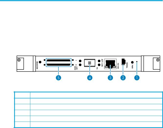
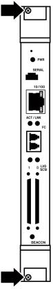
Figure 1 shows the layout of the HP e1200-320 4Gb FC Interface Card.
Figure 1 HP e1200-320 4Gb Interface Card ports
Table 2 HP e1200-320 4Gb Interface Card
Number Description
1Reset access hole
2Serial management port
310/100 Ethernet management port
4Fibre Channel network port
5Two SCSI busses
In addition to Fibre Channel and SCSI interfaces, there are Ethernet and serial ports that provide connectivity for configuration and management access. The LEDs (operation indicators) provide basic status information. A reset button is also provided for a manually forced reboot of the interface card.
e1200-320 4Gb Fibre Channel Interface Card user and service guide |
9 |
Operation indicators
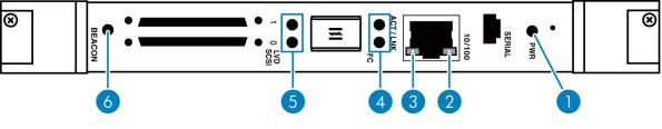
The HP e1200-320 4Gb FC Interface Card has LED indicators for monitoring overall status as shown in Figure 2.
Figure 2 Operation indictors
Table 3 |
Operation indicators |
|
|
|
|
Number |
|
Description |
|
|
|
1 |
|
Power LED |
|
|
|
2 |
|
Ethernet link indicator |
|
|
|
3 |
|
Ethernet activity indicator |
|
|
|
4 |
|
ACT (activity) /LNK (link) LED indicators for the Fibre Channel port |
|
|
|
5 |
|
Activity indicators for the SCSI busses(1, 0) |
|
|
|
6 |
|
Beacon indicator |
|
|
|
The LED functionality of the interface card is detailed below:
•Power and Fault (Pwr) – The bi-color LED is green when power is active, and is continuously amber-colored when the interface card detects a fault condition.
•Fibre Channel Act – When green, the right ACT indicator signifies a good Fibre Channel link.
•Fibre Channel LNK – When green, the left LNK indicator signifies Fibre Channel port activity.
•SCSI bus (0, 1) – When lit, these green indicators signify SCSI activity on the bus corresponding to the number of the indicator.
•Ethernet (10/100) – When lit, these green indicators signify Ethernet link status and activity.
•Beacon – This blue indicator can blink or light continuously for unit identification.
10 Introduction
How the HP e1200-320 4Gb FC Interface Card works
The interface card is a device that translates the Fibre Channel Protocol (FCP) to and from the SCSI Protocol—transparently transferring commands, data, and status information—so that both the Fibre Channel (FC) and SCSI devices and hosts can communicate with each other. Interconnection is provided between two SCSI buses and one Fibre Channel Arbitrated Loop or Switched Fabric, making use of Fibre Channel’s ability to encapsulate SCSI protocol packets.
Processing SCSI information
The following section describes how the interface card processes SCSI information when attached to FC hosts.
1.A FC host issues a command. The FC host encapsulates the command in the FCP protocol and sends the packet to the interface card.
2.The internal FC interface card receives the packet, interprets the FC information, and places the packet in buffer memory.
3.The processor interprets the information and programs an internal SCSI controller to process the transaction.
4.The SCSI controller sends the command to the SCSI device (target).
5.The SCSI target interprets the command and executes it.
6.Data flows between the FC host and SCSI target through payload buffers.
7.Response information flows from the SCSI target back to the FC host.
HP e1200-320 4Gb FC Interface Card features
Fibre Channel features
•One FC port (selectable between 4.25, 2.125 and 1.0625 Gbps)
•Fibre Channel Arbitrated Loop (FC-AL) including Point-to-Point configurations in arbitrated loop topology only and Switched Fabric (FC-SW) topologies
•Private Loop Direct Attach (PLDA) profile compliant
•Class 3 operation with SCSI-FCP protocol
•Supports FCP-2 error recovery protocol as specified in FCP-2 rev. 04 and 05 for use with streaming devices (such as tape)
•Optical SFP support (Shortwave)
SCSI bus features
•Auto-negotiation for Narrow, Wide, Fast, and up to Ultra320
•Concurrent commands, tagged command queuing and disconnect/reconnect
•SCSI-2 and SCSI-3 protocols
•Connection type is VHDCI 68-pin D shell, P type connectors
•LVD/single-ended termination
•Disk, tape, optical, and changer devices
Management features
•Interface card LUN commands
•Out-of-band Ethernet TCP/IP management access
•DHCP for easier network addressing
•Serial 3-pin connector for terminal access
•Ethernet RJ-45 connector for FTP, Telnet, and Web browser access
•Firmware that can be updated in the field
•SCC (FC only), Indexed, and Auto Assigned addressing modes
e1200-320 4Gb Fibre Channel Interface Card user and service guide 11
External indicators
•Fibre Channel link status and activity LEDs
•SCSI bus activity LEDs
•Ethernet link status and activity LEDs
•Power/Fault LED
•Beacon LED
Operating environment
•0 to 50°C, 32 to 122°F
•5 to 80% relative humidity (non-condensing)
Non-operating environment (i.e. for unit storage)
•-40 to +55°C, -40 to 131°F
•0 to 92% relative humidity (non-condensing)
HP e1200-320 4Gb Interface Card benefits
The interface card is designed to connect SCSI devices into a Fibre Channel (FC) fabric or loop. The interface card comes with one 4 Gb/s Fibre Channel port and two LVD/SE SCSI buses.
The Fibre Channel ports can be set for 1, 2, or 4 Gb/s speeds and can connect in arbitrated loop (including point-to-point configurations) or switched fabric topologies. SCSI buses automatically negotiate for Fast, Narrow, Wide, and up to Ultra320 SCSI.
12 Introduction

2 Installation, cabling, and setup
This chapter describes installing, cabling, and setup for the HP e1200-320 4Gb Interface Card.
 NOTE: Read this chapter carefully and completely before working with the interface card.
Installing the HP e1200-320 4Gb Interface Card
Before you begin, clear a work surface near the library to unpack the interface card. Keep the card in the static-sensitive bag until you are ready to install it.
Identifying product components
The interface card kit:
•HP e1200-320 4Gb Interface Card
•Documentation bundle
•Documentation CD
•Installation poster
•Safety CD
•Warranty guide
•HP product documentation survey
•Serial cable
•Two SCSI cables, 0.5 m VHDCI-VHDCI
•Installation poster
e1200-320 4Gb Fibre Channel Interface Card user and service guide 13
Removal and installation
NOTE: To avoid damage to the library, ensure cards are installed in the correct option slots. If you are installing one card, place it in the middle slot next to the controller board. If you are installing two cards in a 10U library, place the second card in the center slot on the bottom level of the library.
Before removing an existing card or installing a new card, do the following:
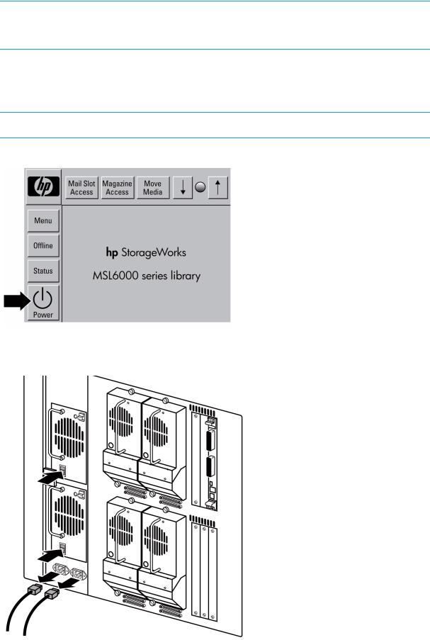
1.Using the library front panel (GUI), turn off power to the library by pressing the Power button (see Figure 3).
NOTE: This process automatically moves the robot to the parked position.
Figure 3 GUI
2.From the back of the library, turn off the master power switch for each power supply.
3.Remove the AC power cord(s) (see Figure 4).
Figure 4 Power supply and AC power cords
14 Installation, cabling, and setup
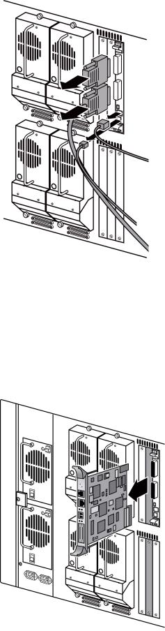
4. Remove the cables from the robotics controller (see Figure 5). Figure 5 Removing cables from the robotics controller
Removing an existing interface card
If you are replacing a card that is already installed in the library, save the configuration settings using the FTP user interface: ftp -> login -> bin -> get *.cfg <path><filename>.cfg. See ”Using the FTP interface” on page 89.
To remove the interface card:
1.From the back of the library, locate the card to be removed (see Figure 6).
2.Using a #1 Phillips screwdriver, loosen the captive screw in each black ejector handle.
3.Push the ejector handles outward, and pull the card out of the library.
Figure 6 Removing an interface card from the library
e1200-320 4Gb Fibre Channel Interface Card user and service guide 15
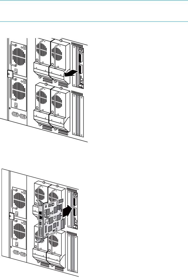
Installing a new card
NOTE: To avoid damage to the library, make sure cards are installed in the correct slots. To install one card, place it in the top level middle slot as shown in Figure 7. To install two cards, place the second card in the bottom level middle slot as also shown in Figure 7.
1. Using a #1 Phillips screwdriver, remove the center option slot cover plate (see Figure 7). Figure 7 Option slots in a 10U library
2.Carefully insert the card into the upper and lower guide rails of the option slot as shown in Figure 8. Resistance is felt as the card connects with the library backplane. Apply only enough force to seat the card snugly, then rotate the ejector handles inward.
Figure 8 Installing the interface card
16 Installation, cabling, and setup
3.Using the #1 Phillips screwdriver, tighten the captive screws in both of the black ejector handles as shown in Figure 9.
Figure 9 Screws in the black ejector handles
e1200-320 4Gb Fibre Channel Interface Card user and service guide 17

4. Cable the library as shown in Figure 10 for a 5U library, or Figure 11 for a 10U library.
Figure 10 5U cable configuration
Figure 11 10U cable configuration
Table 4 Cable connections
Number Description
1 |
SCSI cable |
|
|
2 |
Terminator |
|
|
3 |
Fibre cable |
18 Installation, cabling, and setup
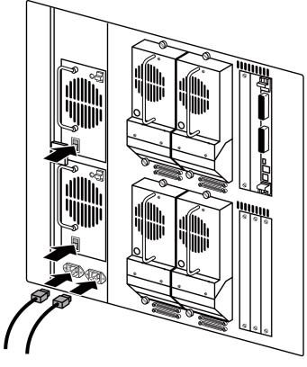
5. Connect each power cord. Turn on the master power switch for each power supply (see Figure 12). Figure 12 Power supply and power cord
6. Turn the library on by pressing the Power button on the GUI control panel (see Figure 3 on page 14).
e1200-320 4Gb Fibre Channel Interface Card user and service guide 19

Interfaces and connections
There are four types of interfaces to the interface card:
•Fibre Channel
•SCSI
•3-pin serial port
•Ethernet
The 3-pin serial and Ethernet ports are used for configuration and management of the interface card.
For convenience in configuring ports, key information is indicated on a label located on the face of the interface card such as WWN name, WWP name, and Ethernet MAC ID (Physical Address).
Fibre Channel connections
Before connecting the interface card to other devices, it is important to understand the configuration requirements of the environment to which it is connected. Failure to correctly configure a Fibre Channel device may impair the operation of the Storage Area Network (SAN) to which it is attached.
Typical installations have the interface card connected to a Switched Fabric environment. For an Arbitrated Loop, the unit can be directly attached to the Fibre Channel host bus adapter. In Fibre Channel switched environments, the switch is also directly attached to the interface card.
Both FC switches and hubs may allow for individual ports to be configured for different media types. The interface card must be connected to the hub or switch port with the appropriate FC cabling for the media type in use on both the interface card and the port to which it is connected.
The interface card supports various Fibre Channel media types through the use of external Small Form Factor Pluggable Transceivers (SFPs).
Supported media type: Multi-Mode Fiber - 4.25 Gbit Dual LC connectors. To connect the interface card to the Fibre Channel SAN:
1.Locate the Fibre Channel port on the interface card (see Figure 1 on page 9).
2.Remove the rubber protector from the SFP.
3.With the library powered off, connect the interface card into the Fibre Channel environment using the appropriate cabling. The FC optical connector on the interface card is keyed. Be sure to insert the cable connectors in the proper orientation.
SCSI connection
The interface card can support Fast/Ultra320 Narrow/Wide SCSI, depending on the specific configuration. The interface card is factory configured to support LVD/Single-Ended buses. Two VHDCI 68-pin D-shell, P-type connectors are available, allowing the unit to be attached at the end of up to two SCSI buses. The interface card must always be installed at the end of SCSI buses.
The interface card supplies termination power (TERMPWR) to each SCSI bus. An internal self-resetting fuse in the TERMPWR resets after a fault is cleared.
 CAUTION: Do not plug HVD devices to an LVD/SE bus. Failure to follow this caution may result in severe damage to equipment.
 CAUTION: SCSI ports on the interface card are not hot-pluggable. Power off the library whenever connecting/disconnecting the SCSI cables.
20 Installation, cabling, and setup
To connect the interface card to a SCSI bus:
1.Power off the SCSI devices on this bus.
2.Connect a SCSI cable to one of the SCSI connectors on the unit. The interface card should always be installed at the end of the SCSI bus.
3.Make sure that the bus is terminated correctly. By default, the interface card is automatically terminated. However, the device at the other end of bus must also be terminated.
Ethernet connection
A 10/100BaseT Ethernet connection provides management and configuration access. The RJ-45 connector on the unit can be directly connected to a standard 10/100BaseT Ethernet network.
NOTE: You should change the pre-filled in settings if you disable DHCP, because while they are valid settings, a conflict occurs if more then one interface card is on the network with these initial settings.
Setting the IP network address is recommended, but not required, in order to configure the interface card from this port. The IP network address can be manually assigned or dynamically assigned (using DHCP). The default network configuration is DHCP, but if DHCP is turned off, the initial value for the IP address is 1.1.1.1, the Subnet is 255.255.255.0, and the Gateway is 0.0.0.0.
Depending on the network environment, you may be able to temporarily use the IP address of 1.1.1.1 to configure the interface card. For more about the IP network address, refer to ”Network configuration” on page 36.
Ethernet capabilities include Telnet support for configuration and management and FTP support for other management capabilities.
Serial port connection
The 3-pin connector on the interface card provides a serial port that is compatible with RS-232 signaling levels. The interface card is designed to communicate with a terminal or any operating system using a terminal emulator. The baud rate, data bits, stop bits, parity, and flow control of both the interface card and the host system must use the same settings. The Autobaud feature described below provides an effective method to set the baud rate of the interface card and host system.
Autobaud feature
The Autobaud feature automatically configures the baud rate on the interface card. Once you set the baud rate in the terminal emulator, wait until the interface card completes the Power-On Self Test (POST) and then the firmware initialization process. This can take up to 90 seconds, during which time the POST and initialization information may or may not be visible on the terminal or terminal emulator. After this process has completed, you can press the Enter key slowly 7 or 8 times (or just type shift-z) and the interface card automatically detects the baud rate being used by the serial port. The baud rate is then saved in the interface card’s configuration and is retained through future power cycles.
 NOTE: Pressing the Enter key before the POST has completed is of no benefit to the Autobaud feature. Wait at least 90 seconds until both the POST and the Firmware Initialization processes have completed before pressing the Enter key.
 NOTE: If there is no response using the Enter key, press the space bar slowly 7 or 8 times, and then press the Enter key slowly 7 or 8 times.
The baud rate used by the terminal or terminal emulator must be 9600, 19200, 38400, 57600, or 115200 for the Autobaud feature to recognize it. The interface card does not function properly at any other baud rate.
e1200-320 4Gb Fibre Channel Interface Card user and service guide 21

Setting up serial port communications
Before supplying power to the interface card, HP recommends setting up serial port communications with your host computer, unless serial I/O was previously established and is currently running.
The interface card is designed to communicate with a terminal or any operating system utilizing a terminal emulator. For example, most Windows® operating systems can use a terminal. Be sure the baud rate, data bits, stop bits, parity, and flow control are set correctly.
To set up serial communications with the interface card:
1.Plug the serial cable into one of the host computer’s serial ports (COM1 or COM2), and then plug the other end of the serial cable into the interface card’s serial port.
2.Start the terminal emulator.
3.Set the terminal emulator to use the appropriate COM port.
4.Specify the following settings for the port:
Baud Rate: |
9600, 19200, 38400, 57600, or 115200 |
|
(Autobaud only recognizes these baud rates) |
|
|
Data Bits: |
8 |
|
|
Stop Bits: |
1 |
|
|
Parity: |
None |
|
|
Flow Control: |
None or XON/XOFF |
|
|
 NOTE: Before initially applying power to the library, make sure all the FC devices are powered on first, and that they have finished performing individual self tests. This helps to ensure that device discovery works correctly.
5.Apply power to the tape library. The power-up process can take up to 90 seconds. Once complete, the main menu should be accessible.
22 Installation, cabling, and setup

3 Device management
To provide connectivity between hosts and devices, it is necessary for the interface card to be recognized with an address on the connected Fibre Channel network.
SCSI bus configuration
The interface card provides the capability to reset SCSI buses during the interface card boot cycle. This allows the devices on a SCSI bus to be set to a known state. Configuration provides for the SCSI bus reset feature to be enabled or disabled.
The interface card negotiates for the maximum values for transfer rates and bandwidth on a SCSI bus. If an attached SCSI device does not allow the full rates, the interface card uses the best rate it can negotiate for that device. Negotiation is on a device specific basis, so the unit can support a mix of SCSI device types on the same SCSI bus.
FC port configuration
By default, the configuration of the FC port on the interface card is set to N_Port mode. For more information, see the Fibre Channel Configuration sections in ”Interface card management” on page 27 and ”Fibre Channel port configuration” on page 42.
FC arbitrated loop addressing
On a Fibre Channel Arbitrated Loop, each device appears as an Arbitrated Loop Physical Address (AL_PA). To obtain an AL_PA, two addressing methods, called soft and hard addressing, can be used by the interface card. Soft addressing is the default setting. For hard addressing, the user specifies the AL_PA of the interface card.
Soft addressing
When acquiring a soft address, the interface card acquires the first available loop address, starting from address 01 and moving up the list of available AL_PAs in the chart from 01 to EF. In this mode, the interface card obtains an available address automatically and then participates on the FC loop, as long as there is at least one address available on the loop connected to the interface card. Fibre Channel supports up to 126 devices on an Arbitrated Loop.
Hard addressing
When acquiring a hard address, the interface card attempts to acquire the AL_PA value specified by the user in the configuration settings. If the desired address is not available at loop initialization time, the interface card comes up on the FC loop using an available soft address. This allows both the loop and the unit to continue to operate. An example of this scenario would be when another device on the Arbitrated Loop has acquired the same address as that configured on the interface card.
Hard addressing is recommended for FC Arbitrated Loop environments where it is important that the FC device addresses do not change. Device address changes can affect the mapping represented by the host operating system to the application, and have adverse effects. An example of this would be a tape library installation, where the application configuration requires fixed device identification for proper operation. Hard addressing ensures that the device identification to the application remains constant.
FC switched fabric addressing
When connected to a Fibre Channel switch, the interface card is identified to the switch as a unique device by the factory programmed World Wide Name (WWN) and the World Wide Port Names (WWPN), which are derived from the WWN.
e1200-320 4Gb Fibre Channel Interface Card user and service guide 23
Discovery
Discovery is a feature that makes it easy to display attached FC and SCSI target devices and have them mapped automatically on the host side for the connected bus/port.
There are two discovery methods available—Manual Discovery and Auto Discovery. Auto Discovery can be set to occur after either reboot events (when the card reboots) or link-up events (for instance, when cables are attached or a hub is rebooted). Discovery can also be turned off by setting the interface card to Manual Discovery Only. The default setting for FC Discovery is Manual Discovery.
For specific information on Discovery settings, see the Fibre Channel configuration and SCSI configuration sections in ”Interface card management” on page 27 and ”Discovery menu” on page 44.
Host bus adapter configuration
A host system using a Fibre Channel Host Bus Adapter (HBA) typically maps devices into the existing device mapping scheme used by the host operating system. Refer to the HBA manual for the mapping table.
Mapping usually involves pairing FC AL_PAs to SCSI target addresses. The HBA claims enough SCSI bus entries to allow for 125 FC targets to map to SCSI bus:Target entries. This is usually done by a fixed mapping of AL_PA to Bus:Target. In such a configuration, the interface card corresponds to a Bus:Target identifier, with the SCSI devices attached to the interface card appearing as logical units (LUNs). Operating systems can extend the available SCSI limit of 15 targets per bus. Although this is not an issue for the operating system or most applications, there are cases where older applications can have expectations about what are valid SCSI IDs, and not correctly handle certain mappings. In particular, applications have been seen to exhibit difficulties addressing target IDs greater than 15 (e.g. 16 and up). This problem can be resolved by configuring the interface card to use hard addressing, and setting the AL_PA used by the unit to a value that the HBA will map to an ID with a value less than 16.
For example, depending on the FC HBA, if the hard AL_PA selection is 1, the interface card address is 1. If the selection is 125, the interface card address is 0xEF. Some FC HBAs configure differently, so verify the AL_PA by reviewing the documentation for the HBA.
Logical unit management
Because SAN resources can be shared, multiple hosts can have access to the same devices on the SAN. To prevent conflicts, the interface card provides the means to restrict access and only allow hosts to find and access selected devices. Simple LUN masking can restrict access, but many times this leaves gaps in the list of LUNs presented to a host, since devices are always associated with fixed LUNs. The interface card, however, provides controlled access to devices by use of LUN management, which goes beyond simple LUN masking.
LUN Management is the ability to present different hosts with different views of the devices accessed through the interface card. For example, one FC host may see three disk LUNs and a tape LUN at LUNs 0 to 3 when it performs discovery on the interface card. Another FC host may only discover a tape LUN at LUN 0. Not only can the administrator control which devices a host may access, but also which LUNs are used to access these devices.
LUN Management is accomplished by allowing the administrator to configure multiple maps, each of which may present a different view of the devices behind the interface card. Each host accessing the interface card can be associated with a specific map.
For a host connected to an FC port, a map is a table of LUNs where each entry in the table is either empty or contains device address information needed to route commands to the appropriate device.
The FC port on the interface card has a set of maps which include user defined maps and a few special predefined maps.
There are currently four special predefined maps: Indexed, Auto Assigned, SCC, and Port 0 device maps. Until a user configures the interface card otherwise, the default map setting is Indexed.
The Indexed map is initially empty and can be modified by the user, however, this is not recommended.
24 Device management
The Auto Assigned map is built dynamically, and contains all the devices found during discovery. This map changes automatically any time the discovery process finds a change in the devices attached to the interface card. This map can be displayed, but cannot be modified directly by the user.
The SCC map is only available on the FC port and contains a single entry. LUN 0 is an interface card LUN, and access to devices behind the controller is handled by using SCC logical unit addressing.
When a host sends a command to the interface card, the interface card selects which map to use, based on the ID of the host sending the command. For FC ports, the host ID is the World Wide Name. For SCSI buses, the host ID is the initiator ID (0 - 15). When a host is unknown to the interface card, or is not attached to a specific map, the interface card uses the default setting for mapping. The default setting for each port can be set to Auto-assigned, Indexed, or SCC (which applies to the FC port only) by the user.
e1200-320 4Gb Fibre Channel Interface Card user and service guide 25
26 Device management

4 Interface card management
The HP e1200-320 4Gb FC Interface Card can be managed over the following user interfaces:
•Over the serial port via a terminal or a terminal emulation utility.
•Over Ethernet via a Telnet utility or an HTTP-based interface called Visual Manager. Additionally, FTP support provides additional management functionality.
Before attempting to configure the interface card, a basic understanding of Fibre Channel and SCSI devices is recommended.
 NOTE: For information on SCSI standards, refer to publications from the X3T10 committee of ANSI (American National Standards Institute). For information on Fibre Channel standards, refer to publications from the X3T11 committee of ANSI. For those who are interested in purchasing approved American National Standards and Technical Reports, you can contact ANSI at (212) 642-4900.
Configuration methods
The interface card can be configured over the serial port via a terminal or terminal emulation utility, over Ethernet via a Telnet utility or Web browser. FTP is also supported on Ethernet, to update firmware revisions.
Serial port management access
The serial port allows for configuration of device characteristics from an attached terminal or terminal emulator.
 NOTE: A Serial connection cannot be made if a Telnet session (discussed later) is already open. If a user attempts to open a serial connection while a Telnet session is already open, the following message appears over the serial interface:
System in use via Telnet. Shell restarted.
The serial interface resumes working when the Telnet session closes.
Out-of-band Ethernet management access
DHCP is enabled by default, and the default network settings that are currently shown are only the values that are pre-loaded if you disable DHCP. The first time you use the interface card, use the serial interface to identify the network settings that were assigned from the DHCP server, or to set a new static setting.
When DHCP is disabled, the pre-filled in values are IP address 1.1.1.1, a subnet mask of 255.255.255.0, and a gateway address of 0.0.0.0. HP recommends that at a minimum, the IP address should be changed.
CAUTION: HP strongly recommends not having two interface cards using the pre-filled in static IP address on the same network, as this causes a conflict.
When setting the IP address for the interface card, there are two options:
•The first option is to enter a fixed, or permanent, IP address for the interface card.
•The second option is to enable DHCP on the interface card, so that a DHCP server (on the Ethernet network used by the interface card) can assign a dynamic IP address to the interface card.
Your DHCP server may also allow you to set up an extended lease reservation for an IP address, by providing the server with the Ethernet MAC address of the interface card. This configures the DHCP server
e1200-320 4Gb Fibre Channel Interface Card user and service guide 27

to always provide the same IP address to the interface card. This setup can be useful for remote management of the interface card via Telnet. Because the method of setting up a lease reservation varies depending on the DHCP server being used, HP recommends that you contact your Network Administrator for assistance.
For more information about enabling DHCP on the interface card, see ”Enabling DHCP on the HP e1200-320 4Gb FC Interface Card” on page 117.
Command Line Interface
The interface card is capable of holding Telnet sessions for configuration purposes. Access to the configuration menus via the serial port will be disabled when a Telnet session is connected. To open a Telnet session, the IP address of the interface card and a Telnet client utility are required.
 NOTE: Rebooting the interface card closes the Telnet session. After the interface card reboots and completes POST, the user must restart or re-open the Telnet session.

 NOTE: Resetting to factory defaults from the Telnet interface does not affect Ethernet activity. User configured values for the IP address, gateway, and subnet mask are retained after the interface card reboots. User name and password are not retained.
 NOTE: The interface card supports only one Telnet session at a time.
From most Windows systems, users can start a Telnet session from the DOS (or Command) prompt using the following steps:
1.From the Windows Start menu, open the DOS (or Command) prompt window.
2.At the ‘>’ prompt, enter the following command
TELNET <IP address>
where <IP address> is the IP address of the interface card. This starts a Telnet session window for the interface card.
3.Enter root for the default user name and password for the default password. HP recommends that you change the user name and password as soon as possible (see ”System menu” on page 34).
4.Access configuration options in the same way used for the serial interface.
5.To exit the Telnet session, select the Disconnect option from your Telnet client utility. In most Telnet utilities, this option is available as a menu item. If working from the Command Prompt in Windows, simply close the window to end the session.
Visual manager
The interface card allows any standard Internet Web browser to view and change the interface card’s configuration with the Visual Manager interface. Information is dynamically generated in an HTML format by the interface card, so that Web browsers can access it.
To access Visual Manager, enter the IP address of the interface card into the Address field of a Web browser. Or, you can enter a URL using a host name defined by the user—for instance, http://HPe1200-3204GbFC (but the user must define the host name on the DNS server first for this to work).
To make changes to interface card settings, use standard keyboard and mouse controls to input information, and then select the Submit button to send the changes to the interface card.
A user name and password are required before any changes can be submitted. The default user name is root and the default password is password. HP recommends that you change the user name and password as soon as possible (see ”Visual manager access” on page 31).
28 Interface card management

Other than dynamic mapping changes, any other changes will not take effect until the next time the interface card reboots. You can force the interface card to reboot by selecting the Reboot option.
For more information about the Visual Manager interface, refer to ”Visual manager access” on page 31.
 NOTE: For the VM interface’s dynamic display of the interface card configuration to be presented properly, use version 6.2 or later of Netscape’s browser on non-Solaris platforms, or Netscape version 6.2.3 for Solaris platforms. If using Internet Explorer, use revision 6.0 or later.
FTP
The interface card includes support of File Transfer Protocol (FTP) for updating firmware, saving trace buffers, and backing up/restoring of configuration settings. FTP functionality is described in more detail in ”Using the Command Line Interface” on page 57. There is also an FTP Utility available within Visual Manager (VM) that is described in ”FTP utility access” on page 50.
Inband SCSI-3 commands
The interface card supports a set of SCSI-3 commands that can be received as FCP commands over the Fibre Channel ports. When using these commands, they must be sent to a tape LUN or interface card LUN of the interface card. For more information, see ”Inband SCSI-3 commands” on page 109 and ”HP e1200-320 4Gb FC Interface Card features” on page 11.
e1200-320 4Gb Fibre Channel Interface Card user and service guide 29
30 Interface card management
Loading...