


 Loading...
HP Color LaserJet 3000/3600/3800 Series printers
Service Manual

HP Color LaserJet 3000/3600/3800 Series printers
Service Manual

Copyright and license
© 2005 Copyright Hewlett-Packard
Development Company, L.P.
Reproduction, adaptation, or translation without prior written permission is prohibited, except as allowed under the copyright laws.
The information contained herein is subject to change without notice.
The only warranties for HP products and services are set forth in the express warranty statements accompanying such products and services. Nothing herein should be construed as constituting an additional warranty. HP shall not be liable for technical or editorial errors or omissions contained herein.
Edition 1, 11/2005
Part number Q5982-90932
Trademark credits
Microsoft® and Windows® are U.S. registered trademarks of Microsoft Corporation.
Linux is a U.S. registered trademark of Linus Torvalds.
PostScript® is a trademarks of Adobe Systems Incorporated.
UNIX® is a registered trademark of The Open Group.
Energy Star® and the Energy Star® logo are U.S. registered marks of the United States Environmental Protection Agency.
Table of contents
1 Product information |
|
Quick access to printer information........................................................................................................ |
2 |
Printers at a glance................................................................................................................................ |
3 |
HP Color LaserJet 3000 Series printer.................................................................................. |
3 |
HP Color LaserJet 3600 Series printer.................................................................................. |
4 |
HP Color LaserJet 3800 Series printer.................................................................................. |
4 |
Features at a glance............................................................................................................................... |
5 |
Walkaround............................................................................................................................................ |
7 |
Control-panel overview........................................................................................................................... |
9 |
Control-panel indicator lights............................................................................................... |
10 |
Display................................................................................................................................. |
10 |
Printer software.................................................................................................................................... |
12 |
HP Color LaserJet 3000 Series printer and HP Color LaserJet 3800 Series printer |
|
drivers.................................................................................................................................. |
12 |
HP Color LaserJet 3600 Series printer drivers.................................................................... |
12 |
Additional drivers................................................................................................................. |
13 |
Software for networks.......................................................................................................... |
13 |
HP Web Jetadmin............................................................................................... |
13 |
UNIX.................................................................................................................... |
13 |
Linux.................................................................................................................... |
14 |
Utilities................................................................................................................................. |
14 |
HP Easy Printer Care Software........................................................................... |
14 |
Embedded Web server....................................................................................... |
14 |
Other components and utilities............................................................................ |
14 |
Print-media specifications.................................................................................................................... |
16 |
Supported media types........................................................................................................ |
16 |
Supported media sizes........................................................................................................ |
16 |
2 Installation and configuration |
|
What is in the box................................................................................................................................. |
20 |
Site requirements................................................................................................................................. |
21 |
Physical specifications......................................................................................................... |
21 |
Connecting to a network or a computer............................................................................................... |
22 |
Printer memory..................................................................................................................................... |
24 |
Installing memory DIMMs.................................................................................................... |
24 |
To install memory and font DIMMs..................................................................... |
24 |
Enabling memory................................................................................................ |
27 |
To enable memory for Windows......................................................... |
27 |
Checking DIMM installation................................................................................. |
27 |
ENWW |
iii |
To check DIMM installation................................................................ |
27 |
3 Maintenance |
|
Understanding approximate supplies-replacement intervals................................................................ |
30 |
Replacing supplies............................................................................................................................... |
31 |
Locating supplies................................................................................................................. |
31 |
Supply replacement guidelines............................................................................................ |
31 |
Replacing the fuser.............................................................................................................. |
32 |
Managing the print cartridge................................................................................................................. |
33 |
HP print cartridges............................................................................................................... |
33 |
Non-HP print cartridges....................................................................................................... |
33 |
Print-cartridge authentication............................................................................................... |
33 |
Print-cartridge storage......................................................................................................... |
33 |
Print-cartridge life expectancy............................................................................................. |
33 |
Checking the supply level.................................................................................................... |
34 |
Using the control panel....................................................................................... |
34 |
Using the embedded Web server........................................................................ |
34 |
Using HP Web Jetadmin..................................................................................... |
34 |
Replacing print cartridges................................................................................... |
34 |
To replace the print cartridge.............................................................. |
35 |
Cleaning the printer.............................................................................................................................. |
37 |
Cleaning spilled toner.......................................................................................................... |
37 |
Vacuum specifications........................................................................................ |
37 |
Calibrating the printer........................................................................................................................... |
38 |
Tools for troubleshooting...................................................................................................................... |
39 |
Using printer information pages........................................................................................... |
39 |
Configuring e-mail alerts...................................................................................................... |
40 |
Using the embedded Web server........................................................................................ |
40 |
To open the embedded Web server by using a network connection.................. |
41 |
Embedded Web server sections......................................................................... |
41 |
Using the HP Easy Printer Care Software........................................................................... |
43 |
Supported operating systems............................................................................. |
43 |
To use the HP Easy Printer Care Software......................................................... |
43 |
HP Easy Printer Care Software sections............................................................ |
44 |
Using the HP Printer Utility for Macintosh............................................................................ |
45 |
To open the HP Printer Utility in Mac OS X V10.2.............................................. |
45 |
To open the HP Printer Utility in Mac OS X V10.3.............................................. |
45 |
HP Printer Utility features.................................................................................... |
45 |
4 Theory of operation |
|
Engine control system.......................................................................................................................... |
48 |
Power-on sequence............................................................................................................. |
49 |
Motors, fans, and solenoids................................................................................................. |
50 |
Laser/scanner system.......................................................................................................................... |
52 |
Pickup-and-feed-system....................................................................................................................... |
53 |
Sensors in the pickup-and-feed system trays (cassettes)................................................... |
54 |
Cassette pickup mechanism................................................................................................ |
55 |
Multipurpose-tray pickup mechanism.................................................................................. |
56 |
Feed-speed control.............................................................................................................. |
56 |
Sensor jam detection........................................................................................................... |
58 |
iv |
ENWW |
Image-formation system....................................................................................................................... |
61 |
Image-formation process..................................................................................................... |
62 |
Latent-image formation stage.............................................................................................. |
63 |
Step 1: pre-exposure........................................................................................... |
63 |
Step 2: primary charging..................................................................................... |
64 |
Step 3: laser-beam exposure.............................................................................. |
64 |
Developing stage................................................................................................................. |
64 |
Step 4: developing.............................................................................................. |
64 |
Transfer stage...................................................................................................................... |
64 |
Step 5: media feed.............................................................................................. |
65 |
Step 6: image transfer......................................................................................... |
65 |
Step 7: separation from the drum........................................................................ |
65 |
Step 8: separation from the ETB......................................................................... |
66 |
Fusing stage........................................................................................................................ |
66 |
Step 9: fusing...................................................................................................... |
66 |
Cleaning stage..................................................................................................................... |
66 |
Step 10: drum cleaning....................................................................................... |
67 |
Print cartridge...................................................................................................................... |
67 |
Print-cartridge activation...................................................................................................... |
68 |
5 Removal and replacement |
|
Removal and replacement strategy...................................................................................................... |
70 |
Introduction.......................................................................................................................... |
70 |
Required tools ..................................................................................................................... |
71 |
Types of screws................................................................................................................... |
72 |
Service approach................................................................................................................. |
73 |
Before performing service.................................................................................................... |
73 |
After performing service....................................................................................................... |
73 |
Print cartridges..................................................................................................................... |
74 |
External doors, covers, and panels...................................................................................................... |
75 |
Front cover........................................................................................................................... |
75 |
Upper cover (fuser door)...................................................................................................... |
80 |
Rear lower cover.................................................................................................................. |
83 |
Left cover............................................................................................................................. |
84 |
Right cover........................................................................................................................... |
87 |
Rear upper cover................................................................................................................. |
91 |
Internal assemblies.............................................................................................................................. |
92 |
Formatter cage.................................................................................................................... |
92 |
Electrostatic transfer belt (ETB)........................................................................................... |
94 |
Fuser.................................................................................................................................... |
95 |
Duplex fan............................................................................................................................ |
96 |
Print-cartridge drive motors................................................................................................. |
99 |
Duplex-reverse-drive assembly......................................................................................... |
100 |
Duplex-feed-drive assembly.............................................................................................. |
103 |
Fuser drive assembly......................................................................................................... |
105 |
Developing separation-drive assembly.............................................................................. |
108 |
Pickup-and-feed assembly................................................................................................ |
111 |
Pickup-drive assembly....................................................................................................... |
116 |
Laser/scanner assembly.................................................................................................... |
125 |
Main fan............................................................................................................................. |
129 |
ENWW |
v |
Printed circuit assemblies (PCAs)...................................................................................................... |
131 |
Low-voltage power-supply PCA......................................................................................... |
131 |
DC controller PCA............................................................................................................. |
135 |
High-voltage power supply................................................................................................ |
137 |
Memory-controller PCA..................................................................................................... |
139 |
Driver PCA......................................................................................................................... |
141 |
Control panel..................................................................................................................... |
143 |
Pickup-and-feed driver PCA.............................................................................................. |
145 |
Duplex-driver PCA............................................................................................................. |
147 |
Sensors.............................................................................................................................................. |
149 |
Cassette media sensor (HP LaserJet 3600/3800)............................................................. |
149 |
Temperature sensor.......................................................................................................... |
151 |
Paper and registration sensor covers................................................................................ |
152 |
Cartridge-sensor PCA........................................................................................................ |
153 |
500-sheet feeder................................................................................................................................ |
156 |
500-sheet feeder right cover.............................................................................................. |
156 |
500-sheet feeder left cover................................................................................................ |
158 |
500-sheet feeder rear cover.............................................................................................. |
161 |
500-sheet feeder driver PCA............................................................................................. |
163 |
Media sensor (500-sheet feeder)....................................................................................... |
165 |
6 Troubleshooting |
|
Troubleshooting process.................................................................................................................... |
170 |
Pre-troubleshooting checklist ............................................................................................ |
170 |
Troubleshooting flowchart.................................................................................................. |
172 |
Power-on checks............................................................................................................... |
172 |
Control-panel messages.................................................................................................................... |
174 |
Jams................................................................................................................................................... |
195 |
Jam recovery..................................................................................................................... |
195 |
Avoiding jams.................................................................................................................... |
196 |
Clearing jams..................................................................................................................... |
197 |
Image-formation troubleshooting....................................................................................... |
207 |
Print-quality problems associated with media................................................... |
207 |
Defects on overhead transparencies................................................................................. |
208 |
Print-quality problems that are related to the environment................................................ |
208 |
Print-quality problems that are related to jams.................................................................. |
209 |
Print-quality problems from toner buildup.......................................................................... |
209 |
Print-quality troubleshooting pages................................................................................... |
209 |
Image defects..................................................................................................................................... |
210 |
Light image........................................................................................................................ |
211 |
Light color.......................................................................................................................... |
211 |
Dark image........................................................................................................................ |
212 |
Dark color.......................................................................................................................... |
212 |
Completely blank image.................................................................................................... |
213 |
All black or solid color........................................................................................................ |
213 |
Dots in vertical lines........................................................................................................... |
213 |
Dirt on back of paper......................................................................................................... |
213 |
Dirt on front of paper.......................................................................................................... |
214 |
Vertical lines ..................................................................................................................... |
214 |
White vertical lines............................................................................................................. |
214 |
vi |
ENWW |
Horizontal line.................................................................................................................... |
215 |
White horizontal line.......................................................................................................... |
215 |
Color missing .................................................................................................................... |
216 |
Blank spots........................................................................................................................ |
216 |
Poor fusing......................................................................................................................... |
216 |
Image distortion................................................................................................................. |
217 |
Color misregistration.......................................................................................................... |
217 |
Smearing........................................................................................................................... |
218 |
Misplaced image................................................................................................................ |
218 |
Reversed color................................................................................................................... |
218 |
Snail tracks........................................................................................................................ |
218 |
Repetitive-defects troubleshooting..................................................................................................... |
220 |
Interface troubleshooting.................................................................................................................... |
222 |
Communication checks...................................................................................................... |
222 |
EIO troubleshooting........................................................................................................... |
222 |
Service menu..................................................................................................................................... |
223 |
Using the Service menu..................................................................................................... |
223 |
Clear event log................................................................................................................... |
223 |
Total page count................................................................................................................ |
223 |
Serial number.................................................................................................................... |
223 |
Diagnostics menu............................................................................................................................... |
224 |
Diagnostics......................................................................................................................................... |
225 |
LED diagnostics................................................................................................................. |
225 |
Diagnostics mode.............................................................................................................. |
225 |
Diagnostics that put the engine into the special diagnostics mode................... |
226 |
Diagnostic tests................................................................................................................. |
226 |
Individual diagnostic tests.................................................................................................. |
227 |
Print the event log page.................................................................................... |
227 |
View the event log on the control-panel display................................................ |
227 |
Print the print-quality (PQ) troubleshooting pages............................................ |
228 |
Disable cartridge check (special mode test)..................................................... |
228 |
Paper-path sensor test...................................................................................... |
228 |
Paper-path test.................................................................................................. |
228 |
Manual sensor test (special mode test)............................................................ |
229 |
Component test (special mode test)................................................................. |
230 |
Print/Stop test.................................................................................................... |
232 |
Test pages.......................................................................................................................................... |
233 |
Engine test page................................................................................................................ |
233 |
Formatter test.................................................................................................................... |
233 |
Half-self test....................................................................................................................... |
233 |
Drum-rotation test.............................................................................................................. |
234 |
Engine resets..................................................................................................................................... |
235 |
Engine resets..................................................................................................................... |
235 |
Cold reset.......................................................................................................... |
235 |
NVRAM initialization.......................................................................................... |
235 |
Hard-disk initialization....................................................................................... |
236 |
Service ID........................................................................................................................................... |
237 |
Converting the Service ID to an actual date...................................................................... |
237 |
ENWW |
vii |
Restoring the Service ID.................................................................................................... |
237 |
Troubleshooting diagrams................................................................................................. |
238 |
Connector locations.......................................................................................... |
238 |
Major assemblies.............................................................................................. |
240 |
DC controller connectors................................................................................... |
245 |
Timing diagram................................................................................................. |
246 |
Circuit diagrams................................................................................................ |
248 |
7 Parts and diagrams |
|
Ordering parts and supplies............................................................................................................... |
252 |
Parts.................................................................................................................................. |
252 |
How to use the parts lists and diagrams............................................................................ |
252 |
Types of screws................................................................................................................. |
252 |
Related documentation and software................................................................................ |
253 |
Accessories and supplies.................................................................................................. |
253 |
External panels and covers................................................................................................................ |
258 |
Internal components........................................................................................................................... |
266 |
Paper-pickup drive assembly............................................................................................................. |
276 |
Duplexing-feed drive assembly (duplex models)................................................................................ |
278 |
Duplexing reverse-drive assembly (duplex models)........................................................................... |
280 |
Developing separation-drive assembly.............................................................................................. |
282 |
Fuser drive assembly......................................................................................................................... |
284 |
Cassette (tray 2)................................................................................................................................. |
286 |
Paper-pickup assembly (HP CLJ 3600/3800).................................................................................... |
288 |
Paper-pickup assembly (HP CLJ 3000)............................................................................................. |
290 |
Electronic transfer belt (simplex models)........................................................................................... |
292 |
Electronic transfer belt (duplex models)............................................................................................. |
294 |
Multipurpose tray assembly (tray 1)................................................................................................... |
296 |
Duplex-paper feed assembly (duplex models)................................................................................... |
298 |
Fuser.................................................................................................................................................. |
300 |
PCAs ................................................................................................................................................. |
302 |
500-sheet feeder cassette (tray 3)..................................................................................................... |
304 |
500-sheet feeder paper-pickup assembly.......................................................................................... |
306 |
500-sheet feeder PCA........................................................................................................................ |
308 |
Alphabetical parts list......................................................................................................................... |
310 |
Numerical parts list............................................................................................................................. |
319 |
Appendix A Printer specifications |
|
Electrical specifications...................................................................................................................... |
330 |
Power-consumption specifications..................................................................................................... |
331 |
Acoustic specifications....................................................................................................................... |
332 |
Operating-environment specifications................................................................................................ |
333 |
Appendix B Product warranty statements |
|
Hewlett-Packard Limited Warranty Statement................................................................................... |
336 |
Availability of support and service...................................................................................................... |
337 |
HP maintenance agreements............................................................................................................. |
337 |
Next-Day Onsite Service................................................................................................... |
337 |
viii |
ENWW |
Appendix C Regulatory statements |
|
FCC regulations................................................................................................................................. |
340 |
Declaration of conformity (HP Color LaserJet 3000 Series printer)................................................... |
341 |
Declaration of conformity (HP Color LaserJet 3600 Series and HP Color LaserJet 3800 Series |
|
printer)................................................................................................................................................ |
342 |
Safety statements............................................................................................................................... |
343 |
Laser safety....................................................................................................................... |
343 |
Canadian DOC regulations................................................................................................ |
343 |
EMI statement (Korea)....................................................................................................... |
343 |
VCCI statement (Japan).................................................................................................... |
343 |
Power cord statement (Japan)........................................................................................... |
343 |
Laser statement for Finland............................................................................................... |
344 |
Index................................................................................................................................................................... |
345 |
ENWW |
ix |
x |
ENWW |
List of tables
Table 1-1 |
Printer guides.................................................................................................................................. |
2 |
Table 1-2 |
HP Color LaserJet 3000 Series printer configurations.................................................................... |
3 |
Table 1-3 |
HP Color LaserJet 3600 Series printer configurations.................................................................... |
4 |
Table 1-4 |
HP Color LaserJet 3800 Series printer configurations.................................................................... |
4 |
Table 1-5 |
Features.......................................................................................................................................... |
5 |
Table 1-6 |
Printer drivers for the HP Color LaserJet 3000 and 3800 Series printers..................................... |
12 |
Table 1-7 |
Tray 1 (multipurpose tray) media types......................................................................................... |
16 |
Table 1-8 |
Tray 2 and tray 3 media types....................................................................................................... |
16 |
Table 1-9 |
Supported media sizes.................................................................................................................. |
16 |
Table 1-10 |
Automatic 2-sided printing ............................................................................................................ |
17 |
Table 2-1 |
Physical dimensions for the HP Color LaserJet 3000/3600/3800 Series printers......................... |
21 |
Table 4-1 |
Sequence of operation.................................................................................................................. |
48 |
Table 6-1 |
Troubleshooting flowchart........................................................................................................... |
172 |
Table 6-2 |
Common causes of jams............................................................................................................. |
196 |
Table 6-3 |
Image defects.............................................................................................................................. |
210 |
Table 6-4 |
Causes for light images............................................................................................................... |
211 |
Table 6-5 |
Causes for one color printing light............................................................................................... |
211 |
Table 6-6 |
Causes for dark images.............................................................................................................. |
212 |
Table 6-7 |
Causes for one color printing darker than others........................................................................ |
212 |
Table 6-8 |
Causes for a completely blank image......................................................................................... |
213 |
Table 6-9 |
Causes for an all black or solid colored image............................................................................ |
213 |
Table 6-10 |
Causes for vertical lines of white dots......................................................................................... |
213 |
Table 6-11 |
Causes for dirt on the back of the paper..................................................................................... |
214 |
Table 6-12 |
Causes for dirt on the front of the paper..................................................................................... |
214 |
Table 6-13 |
Causes for vertical lines.............................................................................................................. |
214 |
Table 6-14 |
Causes for white vertical lines..................................................................................................... |
215 |
Table 6-15 |
Causes for horizontal line............................................................................................................ |
215 |
Table 6-16 |
Causes for white horizontal lines................................................................................................ |
215 |
Table 6-17 |
Causes for a missing color.......................................................................................................... |
216 |
Table 6-18 |
Causes for blank spots................................................................................................................ |
216 |
Table 6-19 |
Causes for poor fusing................................................................................................................ |
216 |
Table 6-20 |
Causes for distortion or blurring.................................................................................................. |
217 |
Table 6-21 |
Causes for color misregistration.................................................................................................. |
217 |
Table 6-22 |
Causes for smearing................................................................................................................... |
218 |
Table 6-23 |
Causes for a misplaced image.................................................................................................... |
218 |
Table 6-24 |
Causes for reversed color........................................................................................................... |
218 |
Table 6-25 |
Causes for snail tracks................................................................................................................ |
218 |
Table 6-26 |
Causes of repetitive defects........................................................................................................ |
220 |
Table 6-27 |
Communication check................................................................................................................. |
222 |
Table 6-28 |
Manual sensor test...................................................................................................................... |
230 |
ENWW |
xi |
Table 7-1 |
Technical support Web sites....................................................................................................... |
253 |
Table 7-2 |
Accessories and supplies............................................................................................................ |
253 |
Table 7-3 |
External panels and covers (1 of 2)............................................................................................ |
259 |
Table 7-4 |
External panels, and covers (2 of 2)........................................................................................... |
261 |
Table 7-5 |
Front-cover assembly (simplex model)....................................................................................... |
263 |
Table 7-6 |
Front-cover assembly (duplex model)......................................................................................... |
265 |
Table 7-7 |
Internal components (1 of 5)....................................................................................................... |
267 |
Table 7-8 |
Internal components (2 of 5)....................................................................................................... |
269 |
Table 7-9 |
Internal components (3 of 5)....................................................................................................... |
271 |
Table 7-10 |
Internal components (4 of 5)....................................................................................................... |
273 |
Table 7-11 |
Internal components (5 of 5)....................................................................................................... |
275 |
Table 7-12 |
Paper-pickup drive assembly...................................................................................................... |
277 |
Table 7-13 |
Duplexing-feed drive assembly (duplex models)........................................................................ |
279 |
Table 7-14 |
Duplexing reverse-drive assembly (duplex models)................................................................... |
281 |
Table 7-15 |
Developing separation-drive assembly....................................................................................... |
283 |
Table 7-16 |
Fuser drive assembly.................................................................................................................. |
285 |
Table 7-17 |
Cassette (tray 2).......................................................................................................................... |
287 |
Table 7-18 |
Paper-pickup assembly (HP CLJ 3600/3800)............................................................................. |
289 |
Table 7-19 |
Paper-pickup assembly (HP CLJ 3000)...................................................................................... |
291 |
Table 7-20 |
Electronic transfer belt (simplex models).................................................................................... |
293 |
Table 7-21 |
Electronic transfer belt (duplex models)...................................................................................... |
295 |
Table 7-22 |
Multipurpose tray assembly (tray 1)............................................................................................ |
297 |
Table 7-23 |
Duplex-paper feed assembly (duplex models)............................................................................ |
299 |
Table 7-24 |
Fuser........................................................................................................................................... |
301 |
Table 7-25 |
PCAs........................................................................................................................................... |
303 |
Table 7-26 |
500-sheet feeder cassette (tray 3).............................................................................................. |
305 |
Table 7-27 |
500-sheet feeder paper-pickup assembly................................................................................... |
307 |
Table 7-28 |
500-sheet feeder PCA................................................................................................................. |
309 |
Table 7-29 |
Alphabetical parts list.................................................................................................................. |
310 |
Table 7-30 |
Numerical parts list...................................................................................................................... |
319 |
Table A-1 |
Electrical specifications for the HP Color LaserJet 3000 Series printers.................................... |
330 |
Table A-2 |
Electrical specifications for the HP Color LaserJet 3600 Series printer...................................... |
330 |
Table A-3 |
Electrical specifications for the HP Color LaserJet 3800 Series printer...................................... |
330 |
Table A-4 |
Power consumption (average, in watts)...................................................................................... |
331 |
Table A-5 |
Acoustic emissions for the HP Color LaserJet 3000 Series printers........................................... |
332 |
Table A-6 |
Acoustic emissions for the HP Color LaserJet 3600 Series printer............................................. |
332 |
Table A-7 |
Acoustic emissions for theHP Color LaserJet 3800 Series printers............................................ |
332 |
Table A-8 |
Operating environment specifications......................................................................................... |
333 |
xii |
ENWW |
List of figures
Figure 1-1 |
Front view (shown with optional 500-sheet paper feeder).............................................................. |
7 |
Figure 1-2 |
Back and side view......................................................................................................................... |
8 |
Figure 1-3 |
Control panel buttons and lights...................................................................................................... |
9 |
Figure 1-4 |
Printer display............................................................................................................................... |
10 |
Figure 2-1 |
What is in the shipping box........................................................................................................... |
20 |
Figure 3-1 |
Supply-item locations.................................................................................................................... |
31 |
Figure 4-1 |
Engine control system components.............................................................................................. |
48 |
Figure 4-2 |
Power-on sequence...................................................................................................................... |
49 |
Figure 4-3 |
Motors, fans, and solenoids.......................................................................................................... |
50 |
Figure 4-4 |
Laser/scanner system................................................................................................................... |
52 |
Figure 4-5 |
Pickup-and-feed system................................................................................................................ |
53 |
Figure 4-6 |
Pickup-and-feed system sensors.................................................................................................. |
54 |
Figure 4-7 |
Cassette pickup mechanism......................................................................................................... |
55 |
Figure 4-8 |
Multipurpose-tray pickup mechanism............................................................................................ |
56 |
Figure 4-9 |
Image formation system................................................................................................................ |
61 |
Figure 4-10 |
Image-formation steps.................................................................................................................. |
63 |
Figure 4-11 |
Pre-exposure................................................................................................................................. |
64 |
Figure 4-12 |
Laser-beam exposure................................................................................................................... |
64 |
Figure 4-13 |
Media feed.................................................................................................................................... |
65 |
Figure 4-14 |
Image transfer............................................................................................................................... |
65 |
Figure 4-15 |
Separation from the drum............................................................................................................. |
66 |
Figure 4-16 |
Fusing........................................................................................................................................... |
66 |
Figure 4-17 |
Print cartridge................................................................................................................................ |
67 |
Figure 4-18 |
Print-cartridge activation............................................................................................................... |
68 |
Figure 5-1 |
Phillips and pozidrive screwdriver comparison............................................................................. |
71 |
Figure 5-2 |
Remove the print cartridges (1 of 2).............................................................................................. |
74 |
Figure 5-3 |
Remove the print cartridges (2 of 2).............................................................................................. |
74 |
Figure 5-4 |
Remove the front cover (1 of 7).................................................................................................... |
75 |
Figure 5-5 |
Remove the front cover (2 of 7).................................................................................................... |
76 |
Figure 5-6 |
Remove the front cover (3 of 7).................................................................................................... |
76 |
Figure 5-7 |
Remove the front cover (4 of 7).................................................................................................... |
77 |
Figure 5-8 |
Remove the front cover (5 of 7).................................................................................................... |
77 |
Figure 5-9 |
Remove the front cover (6 of 7).................................................................................................... |
78 |
Figure 5-10 |
Remove the front cover (7 of 7).................................................................................................... |
79 |
Figure 5-11 |
Remove the upper cover (1 of 5).................................................................................................. |
80 |
Figure 5-12 |
Remove the upper cover (2 of 5).................................................................................................. |
80 |
Figure 5-13 |
Remove the upper cover (3 of 5).................................................................................................. |
81 |
Figure 5-14 |
Remove the upper cover (4 of 5).................................................................................................. |
81 |
Figure 5-15 |
Remove the upper cover (5 of 5).................................................................................................. |
82 |
Figure 5-16 Remove the rear lower cover (1 of 2)............................................................................................ |
83 |
|
ENWW |
xiii |
Figure 5-17 Remove the rear lower cover (2 of 2)............................................................................................ |
83 |
Figure 5-18 Remove the left cover (1 of 5)....................................................................................................... |
84 |
Figure 5-19 Remove the left cover (2 of 5)....................................................................................................... |
84 |
Figure 5-20 Remove the left cover (3 of 5)....................................................................................................... |
85 |
Figure 5-21 Remove the left cover (4 of 5)....................................................................................................... |
85 |
Figure 5-22 Remove the left cover (5 of 5)....................................................................................................... |
86 |
Figure 5-23 Remove the right cover (1 of 4)..................................................................................................... |
87 |
Figure 5-24 Remove the right cover (2 of 4)..................................................................................................... |
88 |
Figure 5-25 Remove the right cover (3 of 4)..................................................................................................... |
89 |
Figure 5-26 Remove the right cover (4 of 4)..................................................................................................... |
90 |
Figure 5-27 Remove the rear upper cover....................................................................................................... |
91 |
Figure 5-28 Remove the formatter cage........................................................................................................... |
93 |
Figure 5-29 Remove the front ETB................................................................................................................... |
94 |
Figure 5-30 Remove the fuser.......................................................................................................................... |
95 |
Figure 5-31 Remove the duplex fan (1 of 3)..................................................................................................... |
96 |
Figure 5-32 Remove the duplex fan (2 of 3)..................................................................................................... |
97 |
Figure 5-33 Remove the duplex fan (3 of 3)..................................................................................................... |
98 |
Figure 5-34 Remove the print-cartridge motor................................................................................................. |
99 |
Figure 5-35 Remove the duplex-reverse-drive assembly (1 of 5).................................................................. |
100 |
Figure 5-36 Remove the duplex-reverse-drive assembly (2 of 5).................................................................. |
101 |
Figure 5-37 Remove the duplex-reverse-drive assembly (3 of 5).................................................................. |
101 |
Figure 5-38 Remove the duplex-reverse-drive assembly (4 of 5).................................................................. |
102 |
Figure 5-39 Remove the duplex-reverse-drive assembly (5 of 5).................................................................. |
102 |
Figure 5-40 Remove the duplex-feed-drive assembly (1 of 2)....................................................................... |
103 |
Figure 5-41 Remove the duplex-feed-drive assembly (2 of 2)....................................................................... |
104 |
Figure 5-42 Remove the fuser drive assembly (1 of 4) ................................................................................. |
105 |
Figure 5-43 Remove the fuser drive assembly (2 of 4) ................................................................................. |
106 |
Figure 5-44 Remove the fuser drive assembly (3 of 4).................................................................................. |
106 |
Figure 5-45 Remove the fuser drive assembly (4 of 4).................................................................................. |
107 |
Figure 5-46 Remove the developing separation-drive assembly (1 of 4)....................................................... |
108 |
Figure 5-47 Remove the developing separation-drive assembly (2 of 4)....................................................... |
109 |
Figure 5-48 Remove the developing separation-drive assembly (3 of 4)....................................................... |
109 |
Figure 5-49 Remove the developing separation-drive assembly (4 of 4)....................................................... |
110 |
Figure 5-50 Remove the pickup-and-feed assembly (1 of 8)......................................................................... |
111 |
Figure 5-51 Remove the pickup-and-feed assembly (2 of 8)......................................................................... |
112 |
Figure 5-52 Remove the pickup-and-feed assembly (3 of 8)......................................................................... |
112 |
Figure 5-53 Remove the pickup-and-feed assembly (4 of 8)......................................................................... |
113 |
Figure 5-54 Remove the pickup-and-feed assembly (5 of 8)......................................................................... |
113 |
Figure 5-55 Remove the pickup-and-feed assembly (6 of 8)......................................................................... |
114 |
Figure 5-56 Remove the pickup-and-feed assembly (7 of 8)......................................................................... |
114 |
Figure 5-57 Remove the pickup-and-feed assembly (8 of 8)......................................................................... |
115 |
Figure 5-58 Remove the pickup-drive assembly (1 of 13).............................................................................. |
117 |
Figure 5-59 Remove the pickup-drive assembly (2 of 13).............................................................................. |
118 |
Figure 5-60 Remove the pickup-drive assembly (3 of 13).............................................................................. |
118 |
Figure 5-61 Remove the pickup-drive assembly (4 of 13).............................................................................. |
119 |
Figure 5-62 Remove the pickup-drive assembly (5 of 13).............................................................................. |
119 |
Figure 5-63 Remove the pickup-drive assembly (6 of 13).............................................................................. |
120 |
Figure 5-64 Remove the pickup-drive assembly (7 of 13).............................................................................. |
121 |
Figure 5-65 Remove the pickup-drive assembly (8 of 13).............................................................................. |
121 |
Figure 5-66 Remove the pickup-drive assembly (9 of 13).............................................................................. |
122 |
xiv |
ENWW |
Figure 5-67 |
Remove the pickup-drive assembly (10 of 13)............................................................................ |
122 |
Figure 5-68 |
Remove the pickup-drive assembly (11 of 13)............................................................................ |
123 |
Figure 5-69 |
Remove the pickup-drive assembly (12 of 13)............................................................................ |
123 |
Figure 5-70 |
Remove the pickup-drive assembly (13 of 13)............................................................................ |
124 |
Figure 5-71 |
Remove the laser/scanner assembly (1 of 6).............................................................................. |
125 |
Figure 5-72 |
Remove the laser/scanner assembly (2 of 6).............................................................................. |
126 |
Figure 5-73 |
Remove the laser/scanner assembly (3 of 6).............................................................................. |
126 |
Figure 5-74 |
Remove the laser/scanner assembly (4 of 6).............................................................................. |
127 |
Figure 5-75 |
Remove the laser/scanner assembly (5 of 6).............................................................................. |
127 |
Figure 5-76 |
Remove the laser/scanner assembly (6 of 6).............................................................................. |
128 |
Figure 5-77 Remove the main fan (1 of 2)...................................................................................................... |
129 |
|
Figure 5-78 Remove the main fan (2 of 2)...................................................................................................... |
130 |
|
Figure 5-79 |
Remove the low-voltage power-supply PCA (1 of 6).................................................................. |
131 |
Figure 5-80 |
Remove the low-voltage power-supply PCA (2 of 6).................................................................. |
132 |
Figure 5-81 |
Remove the low-voltage power-supply PCA (3 of 6).................................................................. |
132 |
Figure 5-82 |
Remove the low-voltage power-supply PCA (4 of 6).................................................................. |
133 |
Figure 5-83 |
Remove the low-voltage power-supply PCA (5 of 6).................................................................. |
133 |
Figure 5-84 |
Remove the low-voltage power-supply PCA (6 of 6).................................................................. |
134 |
Figure 5-85 |
Remove the DC controller PCA (1 of 3)...................................................................................... |
135 |
Figure 5-86 |
Remove the DC controller PCA (2 of 3)...................................................................................... |
136 |
Figure 5-87 |
Remove the DC controller PCA (3 of 3)...................................................................................... |
136 |
Figure 5-88 |
Remove the high-voltage power supply (1 of 3).......................................................................... |
137 |
Figure 5-89 |
Remove the high-voltage power supply (2 of 3).......................................................................... |
138 |
Figure 5-90 |
Remove the high-voltage power supply (3 of 3).......................................................................... |
138 |
Figure 5-91 |
Remove the memory-controller PCA (1 of 2).............................................................................. |
139 |
Figure 5-92 |
Remove the memory-controller PCA (2 of 2).............................................................................. |
140 |
Figure 5-93 |
Remove the driver PCA (1 of 2).................................................................................................. |
141 |
Figure 5-94 |
Remove the driver PCA (2 of 2).................................................................................................. |
142 |
Figure 5-95 |
Remove the control panel (1 of 2)............................................................................................... |
143 |
Figure 5-96 |
Remove the control panel (2 of 2)............................................................................................... |
144 |
Figure 5-97 |
Remove the pickup-and-feed driver PCA (1 of 3)....................................................................... |
145 |
Figure 5-98 |
Remove the pickup-and-feed driver PCA (2 of 3)....................................................................... |
146 |
Figure 5-99 |
Remove the pickup-and-feed driver PCA (3 of 3)....................................................................... |
146 |
Figure 5-100 |
Remove the duplex-driver PCA (1 of 3)...................................................................................... |
147 |
Figure 5-101 |
Remove the duplex-driver PCA (2 of 3)...................................................................................... |
148 |
Figure 5-102 |
Remove the duplex-driver PCA (3 of 3)...................................................................................... |
148 |
Figure 5-103 |
Remove the cassette media sensor (1 of 2)............................................................................... |
149 |
Figure 5-104 |
Remove the cassette media sensor (2 of 2)............................................................................... |
150 |
Figure 5-105 |
Remove the temperature sensor................................................................................................. |
151 |
Figure 5-106 |
Remove the paper and registration sensor covers..................................................................... |
152 |
Figure 5-107 |
Remove the cartridge-sensor PCA (1 of 4)................................................................................. |
153 |
Figure 5-108 |
Remove the cartridge-sensor PCA (2 of 4)................................................................................. |
154 |
Figure 5-109 |
Remove the cartridge-sensor PCA (3 of 4)................................................................................. |
154 |
Figure 5-110 |
Remove the cartridge-sensor PCA (4 of 4)................................................................................. |
155 |
Figure 5-111 |
Remove the 500-sheet feeder right cover (1 of 3)...................................................................... |
156 |
Figure 5-112 |
Remove the 500-sheet feeder right cover (2 of 3)...................................................................... |
157 |
Figure 5-113 |
Remove the 500-sheet feeder right cover (3 of 3)...................................................................... |
157 |
Figure 5-114 |
Remove the 500-sheet feeder left cover (1 of 5)......................................................................... |
158 |
Figure 5-115 |
Remove the 500-sheet feeder left cover (2 of 5)......................................................................... |
159 |
Figure 5-116 |
Remove the 500-sheet feeder left cover (3 of 5)......................................................................... |
159 |
ENWW |
xv |
Figure 5-117 |
Remove the 500-sheet feeder left cover (4 of 5)......................................................................... |
160 |
Figure 5-118 |
Remove the 500-sheet feeder left cover (5 of 5)......................................................................... |
160 |
Figure 5-119 |
Remove the 500-sheet feeder rear cover (1 of 3)....................................................................... |
161 |
Figure 5-120 |
Remove the 500-sheet feeder rear cover (2 of 3)....................................................................... |
162 |
Figure 5-121 |
Remove the 500-sheet feeder rear cover (3 of 3)....................................................................... |
162 |
Figure 5-122 |
Remove the 500-sheet-feeder driver PCA (1 of 2)...................................................................... |
163 |
Figure 5-123 |
Remove the 500-sheet-feeder driver PCA (2 of 2)...................................................................... |
164 |
Figure 5-124 |
Remove the media sensor (500-sheet feeder) (1 of 4)............................................................... |
165 |
Figure 5-125 |
Remove the media sensor (500-sheet feeder) (2 of 4)............................................................... |
166 |
Figure 5-126 |
Remove the media sensor (500-sheet feeder) (3 of 4)............................................................... |
166 |
Figure 5-127 |
Remove the media sensor (500-sheet feeder) (4 of 4)............................................................... |
167 |
Figure 6-1 |
Jam locations (printer shown without optional tray 3)................................................................. |
195 |
Figure 6-2 |
Repetitive defect ruler................................................................................................................. |
221 |
Figure 6-3 |
Door switch and fuser interlock................................................................................................... |
227 |
Figure 6-4 |
Engine test page......................................................................................................................... |
233 |
Figure 6-5 |
Printer connector locations.......................................................................................................... |
238 |
Figure 6-6 |
500-sheet tray connector locations............................................................................................. |
239 |
Figure 6-7 |
Major assemblies (1 of 5)............................................................................................................ |
240 |
Figure 6-8 |
Major assemblies (2 of 5)............................................................................................................ |
241 |
Figure 6-9 |
Major assemblies (3 of 5)............................................................................................................ |
242 |
Figure 6-10 Major assemblies (4 of 5)............................................................................................................ |
243 |
|
Figure 6-11 Major assemblies (5 of 5)............................................................................................................ |
244 |
|
Figure 6-12 DC controller connectors............................................................................................................. |
245 |
|
Figure 6-13 |
Timing diagram (HP LaserJet 3000/3800).................................................................................. |
246 |
Figure 6-14 |
Timing diagram (HP LaserJet 3600)........................................................................................... |
247 |
Figure 6-15 |
General circuit diagram (1 of 2)................................................................................................... |
249 |
Figure 6-16 |
General circuit diagram (2 of 2)................................................................................................... |
250 |
Figure 7-1 |
External panels and covers (1 of 2)............................................................................................ |
258 |
Figure 7-2 |
External panels and covers (2 of 2)............................................................................................ |
260 |
Figure 7-3 |
Front-cover assembly (simplex model)....................................................................................... |
262 |
Figure 7-4 |
Front-cover assembly (duplex model)......................................................................................... |
264 |
Figure 7-5 |
Internal components (1 of 5)....................................................................................................... |
266 |
Figure 7-6 |
Internal components (2 of 5)....................................................................................................... |
268 |
Figure 7-7 |
Internal components (3 of 5)....................................................................................................... |
270 |
Figure 7-8 |
Internal components (4 of 5)....................................................................................................... |
272 |
Figure 7-9 |
Internal components (5 of 5)....................................................................................................... |
274 |
Figure 7-10 |
Paper-pickup drive assembly...................................................................................................... |
276 |
Figure 7-11 |
Duplexing-feed drive assembly (duplex models)........................................................................ |
278 |
Figure 7-12 |
Duplexing reverse-drive assembly (duplex models)................................................................... |
280 |
Figure 7-13 |
Developing separation-drive assembly....................................................................................... |
282 |
Figure 7-14 Fuser drive assembly.................................................................................................................. |
284 |
|
Figure 7-15 |
Cassette (tray 2).......................................................................................................................... |
286 |
Figure 7-16 |
Paper-pickup assembly (HP CLJ 3600/3800)............................................................................. |
288 |
Figure 7-17 |
Paper-pickup assembly (HP CLJ 3000)...................................................................................... |
290 |
Figure 7-18 |
Electronic transfer belt (simplex models).................................................................................... |
292 |
Figure 7-19 |
Electronic transfer belt (duplex models)...................................................................................... |
294 |
Figure 7-20 |
Multipurpose tray assembly (tray 1)............................................................................................ |
296 |
Figure 7-21 Duplex-paper feed assembly (duplex models)............................................................................ |
298 |
|
Figure 7-22 |
Fuser........................................................................................................................................... |
300 |
Figure 7-23 |
PCAs........................................................................................................................................... |
302 |
xvi |
ENWW |
Figure 7-24 |
500-sheet feeder cassette (tray 3).............................................................................................. |
304 |
Figure 7-25 |
500-sheet feeder paper-pickup assembly................................................................................... |
306 |
Figure 7-26 |
500-sheet feeder PCA................................................................................................................. |
308 |
ENWW |
xvii |
xviii |
ENWW |
1 Product information
●Quick access to printer information
●Printers at a glance
●Features at a glance
●Walkaround
●Control-panel overview
●Printer software
●Print-media specifications
ENWW |
1 |

Quick access to printer information
Several references are available for use with this printer.
●HP Color LaserJet 3000 Series printer: www.hp.com/support/clj3000.
●HP Color LaserJet 3600 Series printer: www.hp.com/support/clj3600.
●HP Color LaserJet 3800 Series printer: www.hp.com/support/clj3800.
Table 1-1 Printer guides
Guide |
Description |
|
|
Getting started guide |
Provides step-by-step instructions for installing and setting up the printer. |
|
|
HP Jetdirect Embedded Print |
Provides instructions to configure and troubleshoot the HP Jetdirect print server. |
Server Administrators Guide |
|
|
|
Accessory and consumable |
Provide step-by-step instructions for installing the accessories and supplies. These guides |
installation guides |
are supplied with the optional printer accessories and supplies. |
|
|
User guide |
Provides detailed information for using and troubleshooting the printer. Available on the |
|
printer CD. |
|
|
Online Help |
Provides information about options that are available in the printer drivers. To view a Help |
|
file, open the online Help through the printer driver. |
|
|
2 Chapter 1 Product information |
ENWW |

Printers at a glance
The HP Color LaserJet 3000, 3600, and 3800 Series printers are available in the following configurations.
HP Color LaserJet 3000 Series printer
Table 1-2 HP Color LaserJet 3000 Series printer configurations
HP Color LaserJet 3000 printer
HP Color LaserJet 3000n printer
HP Color LaserJet 3000dn printer
HP Color LaserJet 3000dtn printer
●Prints up to 30 pages per minute (ppm) on letter-size media or
29 ppm on A4-size media in monochrome (black and white) and 15 ppm in color
●100-sheet multipurpose tray (tray 1) and 250-sheet input tray (tray 2)
●Hi-Speed universal serial bus (USB) 2.0 port and enhanced input/output (EIO) slot
●64 MB RAM
The features of the |
The features of the |
The features of the |
|||
HP Color LaserJet 3000 |
HP Color LaserJet 3000 |
HP Color LaserJet 3000 |
|||
printer, plus: |
printer, plus: |
printer, plus: |
|||
● |
64 MB RAM (128 |
● |
192 MB RAM (256 |
● |
192 MB RAM (256 |
|
total) |
|
total) |
|
total) |
● |
HP Jetdirect full- |
● |
HP Jetdirect full- |
● |
HP Jetdirect full- |
|
featured embedded |
|
featured embedded |
|
featured embedded |
|
print server to |
|
print server to |
|
print server to |
|
connect to 10Base-T/ |
|
connect to 10Base- |
|
connect to 10Base-T/ |
|
100 Base-TX |
|
T/100 Base-TX |
|
100 Base-TX |
|
networks |
|
networks |
|
networks |
|
|
● |
Automatic 2-sided |
● |
Automatic 2-sided |
|
|
|
(duplex) printing |
|
(duplex) printing |
|
|
|
|
● |
500-sheet input tray |
|
|
|
|
|
(tray 3) |
ENWW |
Printers at a glance |
3 |

HP Color LaserJet 3600 Series printer
Table 1-3 HP Color LaserJet 3600 Series printer configurations
HP Color LaserJet 3600 printer |
HP Color LaserJet 3600n printer |
HP Color LaserJet 3600dn printer
●17 ppm print speed
●100-sheet multipurpose tray (tray 1) and 250-sheet input tray (tray 2)
●Hi-Speed USB 2.0 port
●64 MB RAM
The features of the HP Color LaserJet 3600 printer, plus:
●HP Jetdirect value-featured embedded print server to connect to 10Base-T/100Base-TX networks
●64 MB RAM
The features of the HP Color LaserJet 3600 printer, plus:
●64 MB RAM (128 total)
●Automatic 2-sided (duplex) printing
●HP Jetdirect value-featured embedded print server to connect to 10Base-T/100Base-TX networks
HP Color LaserJet 3800 Series printer |
||
Table 1-4 HP Color LaserJet 3800 Series printer configurations |
||
HP Color LaserJet 3800 printer |
HP Color LaserJet 3800n |
HP Color LaserJet |
|
printer |
3800dn printer |
HP Color LaserJet 3800dtn printer
● |
22 ppm (letter-size) or 21 ppm |
The features of the |
The features of the |
The features of the |
|
(A4) print speed |
HP Color LaserJet 3800 |
HP Color LaserJet 3800 |
HP Color LaserJet 3800 |
|
|
printer, plus: |
printer, plus: |
printer, plus: |
●100-sheet multipurpose tray
|
(tray 1) and 250-sheet input tray |
● |
64 MB RAM (160 |
● |
192 MB RAM (288 |
● |
192 MB RAM (288 |
|
(tray 2) |
|
total) |
|
total) |
|
total) |
● |
Hi-Speed USB 2.0 port and EIO |
● |
HP Jetdirect full- |
● |
Automatic 2-sided |
● |
Automatic 2-sided |
|
slot |
|
featured embedded |
|
(duplex) printing |
|
(duplex) printing |
● |
96 MB RAM |
|
print server to |
● |
HP Jetdirect full- |
● |
HP Jetdirect full- |
|
connect to 10Base-T/ |
||||||
|
|
|
100Base-TX |
|
featured embedded |
|
featured embedded |
|
|
|
networks |
|
print server to connect |
|
print server to |
|
|
|
|
|
to 10Base-T/ |
|
connect to 10Base-T/ |
|
|
|
|
|
100Base-TX |
|
100Base-TX |
|
|
|
|
|
networks |
|
networks |
|
|
|
|
|
|
● |
500-sheet input tray |
|
|
|
|
|
|
|
(tray 3) |
4 |
Chapter 1 |
Product information |
ENWW |

Features at a glance
Table 1-5 Features
Feature |
HP Color LaserJet 3000 Series |
|
printer |
HP Color LaserJet 3600 Series printer
HP Color LaserJet 3800 Series printer
Performance |
● |
533 MHz processor |
● |
360 MHz processor |
● |
533 MHz processor |
|
|
|
|
|
|
|
User interface |
● |
Graphic display |
● |
Graphic display |
● |
Graphic display |
|
● |
Control-panel help |
● |
Control-panel help |
● |
Control-panel help |
|
● HP Easy Printer Care Software (a |
● HP Easy Printer Care Software |
● HP Easy Printer Care Software |
|||
|
|
Windows®- or Macintosh-based |
|
(a Windowsor Macintosh- |
|
(a Windowsor Macintosh-based |
|
|
status and troubleshooting tool) |
|
based status and |
|
status and troubleshooting tool) |
|
● Windows and Macintosh printer |
|
troubleshooting tool) |
● Windows and Macintosh printer |
||
|
● Windows and Macintosh printer |
|||||
|
|
drivers |
|
drivers |
||
|
● Embedded Web server to gain |
|
drivers |
● Embedded Web server to gain |
||
|
● Embedded Web server to |
|||||
|
|
access to support and to order |
|
access to support and to order |
||
|
|
supplies (administrator tool for |
|
configure network settings only |
|
supplies (administrator tool for |
|
|
network-connected models only) |
|
(administrator tool for network- |
|
network-connected models only) |
|
● |
HP formatter |
|
connected models only) |
● |
HP formatter |
|
● |
Host formatter |
||||
|
|
|
|
|
||
|
|
|
|
|
|
|
Printer drivers |
● |
HP PCL 5c |
HP JetReady 4.2 |
● |
HP PCL 5c |
|
|
● |
HP PCL 6 |
|
|
● |
HP PCL 6 |
|
● |
PostScript® 3 emulation |
|
|
● |
PostScript 3 emulation |
Storage features |
● |
Fonts, forms, and other macros |
None |
● Fonts, forms, and other macros |
||
|
● |
Job retention |
|
|
● |
Job retention |
|
|
|
|
|
||
Fonts |
● |
80 internal fonts available for both |
None |
● 80 internal fonts available for |
||
|
|
PCL and PostScript 3 emulation |
|
|
|
both PCL and PostScript 3 |
|
● 80 printer-matching screen fonts |
|
|
|
emulation |
|
|
|
|
● 80 printer-matching screen fonts |
|||
|
|
in TrueType format available with |
|
|
||
|
|
the software solution |
|
|
|
in TrueType format available with |
|
|
|
|
|
|
the software solution |
|
|
|
|
|
||
Accessories |
● |
Optional 500-sheet input tray |
● Optional 500-sheet input tray |
● Optional 500-sheet input tray |
||
|
|
(tray 3) (standard on the |
|
(tray 3) |
|
(tray 3) (standard on the |
|
|
HP Color LaserJet 3000dtn |
|
|
|
HP Color LaserJet 3800dtn |
|
|
printer) |
|
|
|
printer) |
|
● Dual inline memory modules |
|
|
● |
DIMMs |
|
|
|
(DIMMs) |
|
|
|
|
|
|
|
|
|
||
Connectivity |
● |
Hi-Speed USB 2.0 cable interface |
● Hi-Speed USB 2.0 cable |
● Hi-Speed USB 2.0 cable |
||
|
● HP Jetdirect full-featured |
|
interface |
|
interface |
|
|
|
|
|
|
||
|
|
embedded print server (standard |
● |
HP Jetdirect value-featured |
● |
HP Jetdirect full-featured |
|
|
on the HP Color LaserJet 3000n, |
|
embedded print server (standard |
|
embedded print server (standard |
|
|
3000dn, and 3000dtn printers) |
|
on the HP Color LaserJet 3600n |
|
on the HP Color LaserJet 3800n, |
|
● HP Web Jetadmin software |
|
and 3600dn printers) |
|
3800dn, and 3800dtn printers) |
|
|
|
|
|
|
||
|
|
(standard on the HP Color |
● HP Web Jetadmin software |
● HP Web Jetadmin software |
||
|
|
|
|
(standard on the HP Color |
|
(standard on the HP Color |
|
|
|
|
LaserJet 3600n and 3600dn |
|
|
|
|
|
|
printers) |
|
|
|
|
|
|
|
|
|
ENWW |
Features at a glance 5 |

Table 1-5 Features (continued)
Feature |
HP Color LaserJet 3000 Series |
|
printer |
HP Color LaserJet 3600 Series printer
HP Color LaserJet 3800 Series printer
|
|
LaserJet 3000n, 3000dn, and |
LaserJet 3800n, 3800dn, and |
|
|
3000dtn printers) |
3800dtn printers) |
|
● |
Enhanced input/output (EIO) slot |
● Enhanced input/output (EIO) slot |
|
|
|
|
Environmental |
● |
Sleep-mode setting |
|
features |
● High content of recyclable components and materials |
|
|
|
|
||
|
● ENERGY STAR® qualified |
|
|
Supplies |
● |
Supplies status page contains information about toner level, page count, and estimated pages remaining |
|
|
● No-shake cartridge design |
|
|
|
● Printer checks for authentic HP print cartridges at cartridge installation |
|
|
|
● Internet-enabled supply-ordering capabilities (using HP Easy Printer Care Software) |
||
|
|
|
|
Accessibility |
● |
The online user guide is compatible with text screen-readers. |
|
● Print cartridges can be installed and removed by using one hand.
● All doors and covers can be opened by using one hand.
● Media can be loaded in tray 1 by using one hand.
6 Chapter 1 Product information |
ENWW |
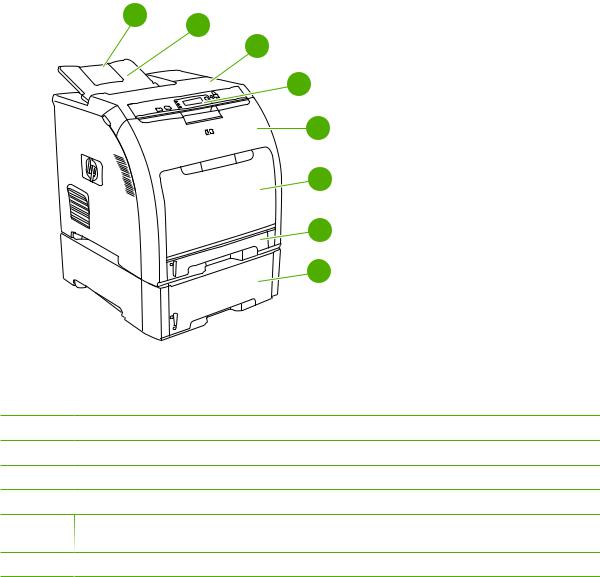
Walkaround
1 2
3
4
5
6
7
8
Figure 1-1 |
Front view (shown with optional 500-sheet paper feeder) |
1 Output bin extender
2 Output bin
3 Top cover (This part is called the upper cover in this service manual.)
4 Printer control panel
5 Front door (This part is called the front cover in this service manual.)
6Tray 1 (holds 100 sheets of standard paper) (This part is called the multipurpose-tray assembly in this service manual.)
7 Tray 2 cassette (holds 250 sheets of standard paper)
8 Tray 3 cassette (optional; holds 500 sheets of standard paper)
ENWW |
Walkaround |
7 |
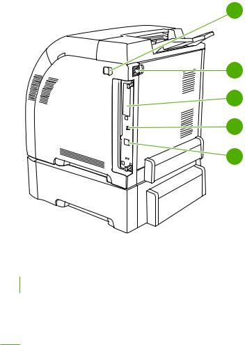
1
2
3
4
5
Figure 1-2 Back and side view
1 |
On/off switch |
|
|
2 |
Power connection |
|
|
3 |
EIO slot (available on the HP Color LaserJet 3000 and 3800 Series printers) |
|
|
4 |
Hi-Speed USB 2.0 port |
5Network port (available on the HP Color LaserJet 3000n, 3000dn, 3000dtn, 3600n, 3600dn, 3800n, 3800dn, and 3800dtn printers)
8 Chapter 1 Product information |
ENWW |
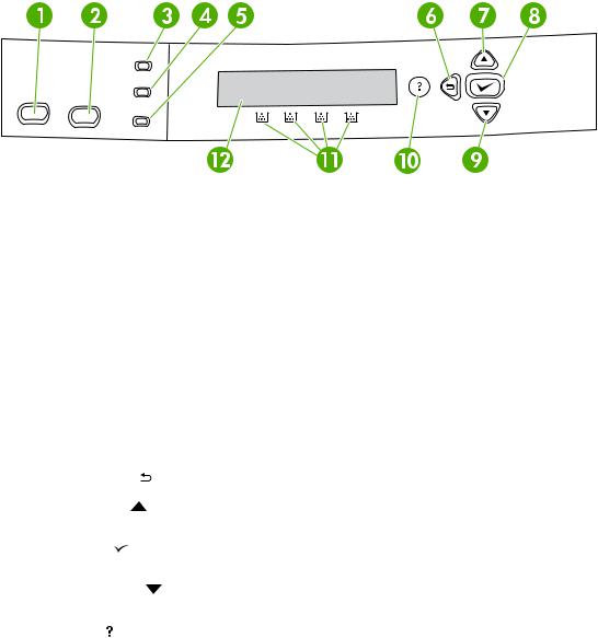
Control-panel overview
The control panel provides controls for printer functions and shows messages about the printer, print jobs, and supplies status.
Figure 1-3 |
Control panel buttons and lights |
|
|||
|
|
|
|
|
|
Number |
|
Button or light |
|
Function |
|
|
|
|
|
|
|
1 |
|
Stop button |
|
Halts the current job, presents a choice to resume or cancel the |
|
|
|
|
|
|
current print job, clears media from the printer, and clears any |
|
|
|
|
|
continuable errors that are associated with the halted job. If the printer |
|
|
|
|
|
is not printing a job, pressing Stop pauses the printer. |
|
|
|
|
|
|
2 |
|
Menu button |
|
Opens and closes menus. |
|
|
|
|
|
|
|
3 |
|
Ready light |
|
Indicates that the printer is online or offline. See Control-panel |
|
|
|
|
|
|
indicator lights on page 10. |
|
|
|
|
|
|
4 |
|
Data light |
|
Indicates whether or not the printer is receiving data. See Control- |
|
|
|
|
|
|
panel indicator lights on page 10. |
|
|
|
|
|
|
5 |
|
Attention light |
|
Indicates that a critical error has occurred. See Control-panel |
|
|
|
|
|
|
indicator lights on page 10. |
|
|
|
|
|
|
6 |
|
Back arrow ( |
) button |
Navigates backward in nested menus. |
|
|
|
|
|
|
|
7 |
|
Up arrow ( |
) button |
Navigates menus and text, and increases the values of numerical |
|
|
|
|
|
|
items in the display. |
|
|
|
|
|
|
8 |
|
Select ( |
) button |
Makes selections, resumes printing after continuable errors, and |
|
|
|
|
|
|
overrides a non-HP print cartridge. |
|
|
|
|
|
|
9 |
|
Down arrow ( |
) button |
Navigates menus and text, and decreases the values of numerical |
|
|
|
|
|
|
items in the display. |
|
|
|
|
|
|
10 |
|
Help ( |
) button |
Provides detailed information about printer messages or menus. |
|
|
|
|
|
||
11 |
|
Supplies gauge |
Shows the print cartridge-consumption levels. See Display |
||
|
|
|
|
|
on page 10. |
|
|
|
|
|
|
12 |
|
Display |
|
|
Shows status information, menus, help information, and error |
|
|
|
|
|
messages. See Display on page 10. |
|
|
|
|
|
|
The printer communicates through the display and the lights on the control panel. The display shows status information, menus, help information, and error messages. The Ready, Data, and Attention lights provide at-a-glance information about the printer state.
ENWW |
Control-panel overview 9 |

You can perform most routine printing tasks from the computer through the printer driver or any software program. Use the control panel to access printer features that the printer driver or software program do not support. Any changes that you make from the computer override the printer control-panel settings. For information about using the printer driver, see Printer software on page 12.
Control-panel indicator lights
Indicator |
On |
Off |
Flashing |
|
|
|
|
Ready (green)
The printer is online (can accept and process data).
The printer is offline (paused), or is turned off.
The printer is attempting to stop printing and go offline. This usually results from a user's request to pause the current job.
Data (green)
The processed data is present in the printer, but more data is needed to complete the job, or the job is paused or waiting for errors to be cleared.
The printer is not processing or receiving data.
The printer is processing and receiving data.
Attention |
A critical error has occurred. |
No conditions exist that |
An error has occurred. The |
(amber) |
The printer requires attention. |
require attention. |
printer requires attention. |
|
|
|
|
|
|
|
|
Display
The printer display gives you complete, timely information about the printer and print jobs. Graphics illustrate levels of supplies. Menus provide access to printer functions and detailed information.
The top-level screen on the display has two areas: message/prompt and supplies gauge.
1 |
2 |
3
Figure 1-4 Printer display
1Message/prompt area
2Supplies gauge
3Print cartridge colors from left to right: black, yellow, cyan, and magenta
The message and prompt areas of the display alert you to the state of the printer and tell you how to respond.
10 Chapter 1 Product information |
ENWW |
Loading...