


 Loading...
HP Integrity BL860c i2, BL870c i2 & BL890c i2 Server Blade User Service Guide
Abstract
This document contains specific information that is intended for users of this HP product.
HP Part Number: 5900-2661
Published: May 2013
Edition: 11

© Copyright 2010, 2013 Hewlett-Packard Development Company, L.P.
The information contained herein is subject to change without notice. The only warranties for HP products and services are set forth in the express warranty statements accompanying such products and services. Nothing herein should be construed as constituting an additional warranty. HP shall not be liable for technical or editorial errors or omissions contained herein.
Acknowledgments
Intel, Pentium, Itanium, Intel Inside, and the Intel Inside logo are trademarks or registered trademarks of Intel Corporation or its subsidiaries in the United States and other countries. UNIX is a registered trademark of The Open Group. Microsoft and Windows are U.S. registered trademarks of Microsoft Corporation.
Warranty
To get a copy of the warranty for this product see the warranty information website:
http://bizsupport2.austin.hp.com/bc/docs/support/SupportManual/c01865770/c01865770.pdf
Revision history
Document manufacturing |
Operating systems |
Supported product |
Edition number |
Publication Date |
part number |
supported |
versions |
|
|
AD399-9003A |
HP-UX |
BL860c i2, BL870c i2 & |
First |
April 2010 |
|
|
BL890c i2 |
|
|
AD399-9003A_ed2 |
HP-UX, OpenVMS, |
BL860c i2, BL870c i2 & |
Second |
September 2010 |
|
Microsoft® Windows® |
BL890c i2 |
|
|
AD399-9003A_ed3 |
HP-UX, OpenVMS, |
BL860c i2, BL870c i2 & |
Third |
December 2010 |
|
Microsoft Windows |
BL890c i2 |
|
|
AD399-9003A_ed4 |
HP-UX, OpenVMS, |
BL860c i2, BL870c i2 & |
Fourth |
February 2011 |
|
Microsoft Windows |
BL890c i2 |
|
|
5992-1024 |
HP-UX, OpenVMS, |
BL860c i2, BL870c i2 & |
Fifth |
May 2011 |
|
Microsoft Windows |
BL890c i2 |
|
|
5992-1050 |
HP-UX, OpenVMS, |
BL860c i2, BL870c i2 & |
Sixth |
August 2011 |
|
Microsoft Windows |
BL890c i2 |
|
|
5992-1076 |
HP-UX, OpenVMS, |
BL860c i2, BL870c i2 & |
Seventh |
November 2011 |
|
Microsoft Windows |
BL890c i2 |
|
|
5992-1081 |
HP-UX, OpenVMS, |
BL860c i2, BL870c i2 & |
Eighth |
February 2012 |
|
Microsoft Windows |
BL890c i2 |
|
|
5992-1089 |
HP-UX, OpenVMS, |
BL860c i2, BL870c i2 & |
Ninth |
September 2012 |
|
Microsoft Windows |
BL890c i2 |
|
|
5900-2649 |
HP-UX, OpenVMS, |
BL860c i2, BL870c i2 & |
Tenth |
February 2013 |
|
Microsoft Windows |
BL890c i2 |
|
|
5900-2661 |
HP-UX, OpenVMS, |
BL860c i2, BL870c i2 & |
Eleventh |
May 2013 |
|
Microsoft Windows |
BL890c i2 |
|
|

Contents |
|
1 Overview.................................................................................................. |
8 |
Server blade overview............................................................................................................... |
8 |
Server blade components.......................................................................................................... |
9 |
2 Site preparation....................................................................................... |
10 |
Server blade dimensions and weight......................................................................................... |
10 |
Enclosure information.............................................................................................................. |
10 |
Enclosure environmental specifications....................................................................................... |
10 |
Sample Site Inspection Checklist............................................................................................... |
11 |
Power subsystem..................................................................................................................... |
13 |
ESD handling information........................................................................................................ |
13 |
Unpacking and inspecting the server blade................................................................................ |
13 |
Verifying site preparation.................................................................................................... |
14 |
Inspect the shipping containers for damage........................................................................... |
14 |
Unpacking the server blade................................................................................................ |
14 |
Verifying the inventory........................................................................................................ |
14 |
Returning damaged equipment............................................................................................ |
14 |
3 Installing the server blade into the enclosure................................................ |
15 |
Installation sequence and checklist............................................................................................ |
15 |
Installing and powering on the server blade............................................................................... |
15 |
Preparing the enclosure...................................................................................................... |
15 |
Removing a c7000 device bay divider............................................................................. |
16 |
Removing a c3000 device bay mini-divider or device bay divider........................................ |
17 |
Installing interconnect modules........................................................................................ |
18 |
Interconnect bay numbering and device mapping......................................................... |
19 |
Installing the server blade into the enclosure.......................................................................... |
20 |
Server blade power states................................................................................................... |
21 |
Powering on the server blade.......................................................................................... |
22 |
Powering off the server blade.......................................................................................... |
22 |
Installing the Blade Link for BL870c i2 or BL890c i2 configurations................................................ |
22 |
Conjoin checks.................................................................................................................. |
25 |
Using iLO 3........................................................................................................................... |
25 |
Accessing UEFI or the OS from iLO 3 MP................................................................................... |
26 |
UEFI Front Page................................................................................................................. |
27 |
Saving UEFI configuration settings................................................................................... |
28 |
Booting and installing the operating system........................................................................... |
28 |
Operating system is loaded onto the server blade.................................................................. |
29 |
Operating system is not loaded onto the server blade............................................................. |
29 |
OS login prompt................................................................................................................ |
29 |
Installing the latest firmware using HP Smart Update Manager..................................................... |
29 |
4 Operating system procedures..................................................................... |
30 |
Operating systems supported on the server blade....................................................................... |
30 |
Installing the operating system onto the server blade................................................................... |
30 |
Installing the OS from an external USB DVD device or tape device........................................... |
30 |
Installing the OS using HP Ignite-UX..................................................................................... |
31 |
Installing the OS using vMedia............................................................................................ |
31 |
Configuring system boot options............................................................................................... |
32 |
Booting and shutting down HP-UX............................................................................................. |
32 |
Adding HP-UX to the boot options list................................................................................... |
32 |
HP-UX standard boot.......................................................................................................... |
33 |
Booting HP-UX from the UEFI Boot Manager..................................................................... |
33 |
Contents 3
Booting HP-UX from the UEFI Shell................................................................................... |
34 |
Booting HP-UX in single-user mode....................................................................................... |
34 |
Booting HP-UX in LVM-maintenance mode............................................................................. |
34 |
Shutting down HP-UX.......................................................................................................... |
34 |
Booting and shutting down HP OpenVMS.................................................................................. |
35 |
Adding OpenVMS to the Boot Options List............................................................................ |
35 |
Booting OpenVMS............................................................................................................. |
36 |
Booting OpenVMS from the UEFI Boot Manager............................................................... |
36 |
Booting HP OpenVMS from the UEFI Shell........................................................................ |
36 |
Shutting Down OpenVMS................................................................................................... |
37 |
Booting and shutting down Microsoft Windows.......................................................................... |
37 |
Adding Microsoft Windows to the boot options list................................................................. |
37 |
Booting the Microsoft Windows operating system................................................................... |
39 |
Shutting down Microsoft Windows....................................................................................... |
39 |
Shutting down Windows from the command line............................................................... |
40 |
5 Optional components................................................................................ |
41 |
Partner blades........................................................................................................................ |
41 |
Hot-plug SAS disk drives.......................................................................................................... |
42 |
Installing internal components.................................................................................................. |
43 |
Removing the access panel................................................................................................. |
43 |
Processor and heatsink module............................................................................................ |
44 |
DIMMs............................................................................................................................. |
49 |
Mezzanine cards............................................................................................................... |
52 |
HP Smart Array P700m/512 Controller................................................................................. |
53 |
Battery kit and other components.................................................................................... |
53 |
Battery mounting bracket parts................................................................................... |
54 |
Installing the Controller Board......................................................................................... |
55 |
Upgrading or replacing controller options........................................................................ |
56 |
Replacing the 512MB cache module........................................................................... |
56 |
Replacing the battery mounting bracket....................................................................... |
57 |
Replacing the BBWC battery...................................................................................... |
58 |
Removing upgrade components...................................................................................... |
60 |
Removing the 512MB cache module............................................................................ |
60 |
Removing the battery mounting bracket....................................................................... |
60 |
Removing the BBWC battery...................................................................................... |
61 |
HP Smart Array P711m Controller......................................................................................... |
62 |
Supercap pack mounting kit........................................................................................... |
62 |
Installing the Supercap mounting bracket.......................................................................... |
63 |
Installing the P711m controller board................................................................................ |
64 |
Installing the Supercap Pack........................................................................................... |
64 |
Replacing the access panel................................................................................................. |
65 |
Upgrading a conjoined configuration................................................................................... |
66 |
Procedure summary....................................................................................................... |
66 |
Upgrade kit contents...................................................................................................... |
66 |
Before getting started..................................................................................................... |
67 |
Supported operating systems..................................................................................... |
67 |
Minimum firmware versions........................................................................................ |
68 |
Determining your current firmware revisions.................................................................. |
68 |
Rules for server blade internal components................................................................... |
72 |
Upgrading the existing server blade................................................................................ |
73 |
Existing server blade check........................................................................................ |
73 |
Adding resources..................................................................................................... |
73 |
Final hardware check................................................................................................ |
78 |
Booting the operating system..................................................................................... |
79 |
4Contents
Warranty registration................................................................................................ |
79 |
Support....................................................................................................................... |
80 |
Blade link and system information parameters................................................................... |
80 |
Operating System Licenses............................................................................................. |
81 |
HP-UX..................................................................................................................... |
81 |
HP OpenVMS.......................................................................................................... |
81 |
Windows Server 2008.............................................................................................. |
81 |
Upgrade scenarios which do not require a reinstall of the operating system.......................... |
82 |
Possible changes due to VC profile mapping on the upgraded server blade.......................... |
82 |
Preserving VC-assigned MAC addresses in HP-UX by enabling Portable Image...................... |
84 |
Pre-Upgrade Procedure for PI..................................................................................... |
85 |
Post-Upgrade Procedure for PI.................................................................................... |
85 |
6 Troubleshooting........................................................................................ |
87 |
Methodology......................................................................................................................... |
87 |
General troubleshooting methodology.................................................................................. |
87 |
Executing recommended troubleshooting methodology .......................................................... |
88 |
Basic and advanced troubleshooting tables........................................................................... |
88 |
Troubleshooting tools.............................................................................................................. |
91 |
Controls and ports............................................................................................................. |
92 |
Front panel view........................................................................................................... |
92 |
Rear panel view............................................................................................................ |
93 |
Server blade LEDs.............................................................................................................. |
93 |
Front panel LEDs........................................................................................................... |
93 |
SAS disk drive LEDs....................................................................................................... |
95 |
SAS hard drive LED combinations............................................................................... |
95 |
Blade Link LEDs............................................................................................................. |
96 |
Virtual Front Panel LEDs in the iLO 3 TUI................................................................................ |
96 |
SUV Cable and Ports.......................................................................................................... |
99 |
Connecting to the serial port........................................................................................... |
99 |
Diagnostics..................................................................................................................... |
100 |
Offline Diagnostics Environment......................................................................................... |
100 |
General diagnostic tools................................................................................................... |
100 |
Fault management overview.............................................................................................. |
101 |
HP-UX Fault management.................................................................................................. |
101 |
Errors and error logs............................................................................................................. |
101 |
Event log definitions......................................................................................................... |
101 |
Event log usage............................................................................................................... |
102 |
iLO 3 MP event logs......................................................................................................... |
102 |
SEL review...................................................................................................................... |
104 |
Troubleshooting processors.................................................................................................... |
105 |
Processor installation order................................................................................................ |
105 |
Processor module behaviors.............................................................................................. |
105 |
Enclosure information............................................................................................................ |
105 |
Cooling subsystem................................................................................................................ |
105 |
Firmware............................................................................................................................. |
105 |
Identifying and troubleshooting firmware issues.................................................................... |
105 |
Verify and install the latest firmware................................................................................... |
106 |
Troubleshooting the server interface (system console)................................................................. |
106 |
Troubleshooting the environment............................................................................................. |
106 |
7 Removing and replacing components........................................................ |
108 |
Server blade components list.................................................................................................. |
108 |
Preparing the server blade for servicing................................................................................... |
110 |
Powering off the server blade............................................................................................ |
110 |
Blade Link for BL870c i2 or BL890c i2 configurations........................................................... |
110 |
Contents 5
Removing the Blade Link for BL870c i2 or BL890c i2 configurations................................... |
110 |
Replacing the Blade Link for BL870c i2 or BL890c i2 configurations................................... |
111 |
Blade Link for BL860c i2 configurations.............................................................................. |
112 |
Server blade........................................................................................................................ |
113 |
Access panel....................................................................................................................... |
113 |
Disk drive blanks.................................................................................................................. |
114 |
Removing a disk drive blank.............................................................................................. |
114 |
Disk drives........................................................................................................................... |
114 |
DIMM baffle........................................................................................................................ |
115 |
DIMMs................................................................................................................................ |
116 |
CPU baffle........................................................................................................................... |
117 |
CPU and heatsink module..................................................................................................... |
118 |
SAS backplane.................................................................................................................... |
121 |
Server battery...................................................................................................................... |
122 |
Mezzanine cards.................................................................................................................. |
123 |
ICH mezzanine board........................................................................................................... |
124 |
System board....................................................................................................................... |
124 |
Blade Link............................................................................................................................ |
125 |
8 Support and other resources.................................................................... |
127 |
Contacting HP...................................................................................................................... |
127 |
Before you contact HP...................................................................................................... |
127 |
HP contact information..................................................................................................... |
127 |
Subscription service.......................................................................................................... |
127 |
Documentation feedback.................................................................................................. |
127 |
HP Insight Remote Support Software................................................................................... |
128 |
New and changed information in this edition........................................................................... |
128 |
Typographic conventions....................................................................................................... |
128 |
Standard terms, abbreviations, and acronyms............................................... |
130 |
A Utilities................................................................................................. |
133 |
Configuring a Smart Array Controller...................................................................................... |
133 |
Using the saupdate command........................................................................................... |
133 |
get_mode.................................................................................................................. |
133 |
set_mode................................................................................................................... |
134 |
Updating the firmware using saupdate........................................................................... |
134 |
Determining the Driver ID and CTRL ID................................................................................ |
134 |
Configuring RAID volumes using the ORCA menu-driven interface............................................... |
135 |
Creating a logical drive.................................................................................................... |
136 |
Deleting a logical drive.................................................................................................... |
137 |
Useful UEFI command checks............................................................................................ |
138 |
UEFI................................................................................................................................... |
139 |
UEFI Shell and HP POSSE commands................................................................................. |
139 |
Drive paths in UEFI............................................................................................................... |
142 |
Using the Boot Maintenance Manager.................................................................................... |
142 |
Boot Options................................................................................................................... |
143 |
Add Boot Option........................................................................................................ |
143 |
Delete Boot Option...................................................................................................... |
144 |
Change Boot Order.................................................................................................... |
145 |
Driver Options................................................................................................................. |
146 |
Add Driver Option...................................................................................................... |
146 |
Delete Driver Option.................................................................................................... |
147 |
Change Driver Order................................................................................................... |
147 |
Console Options.............................................................................................................. |
147 |
Boot From File................................................................................................................. |
147 |
6Contents
Set Boot Next Value |
.........................................................................................................148 |
Set Time Out Value.......................................................................................................... |
148 |
Reset System.................................................................................................................... |
149 |
iLO 3 MP............................................................................................................................. |
149 |
Index....................................................................................................... |
150 |
Index....................................................................................................... |
154 |
Contents 7

1 Overview
The HP Integrity BL860c i2 Server Blade is a dense, low-cost, Intel® Itanium® processor server blade. Using a Blade Link hardware assembly, multiple BL860c i2 Server Blades can be conjoined to create dual-blade, four socket and quad-blade, eight socket variants.
Name |
Number of Conjoined Server Blades |
Number of Processor Sockets |
BL860c i2 |
1 |
2 |
BL870c i2 |
2 |
4 |
BL890c i2 |
4 |
8 |
The three blade configurations support the HP-UX, HP OpenVMS, and Windows operating systems and are designed for deployment in c-Class enclosures, specifically the 10U c7000 and the 6U c3000 Enclosures.
NOTE: For purposes of this guide, make sure that the c-Class server blade enclosure is powered on and running properly and that the OA iLO 3 is operational.
Server blade overview
Product |
CPU cores (quad) |
DIMM slots |
BL860c i2 |
8 |
24 |
BL870c i2 |
16 |
48 |
BL890c i2 |
32 |
96 |
|
PCIe I/O |
|
|
Mezzanine card |
SAS Hard Disk |
max memory |
capacity |
Drives |
384GB with |
3 |
2 |
16GB DIMMs |
|
|
768GB with |
6 |
4 |
16GB DIMMs |
|
|
1.5TB with 16GB |
12 |
8 |
DIMMs |
|
|
8Overview
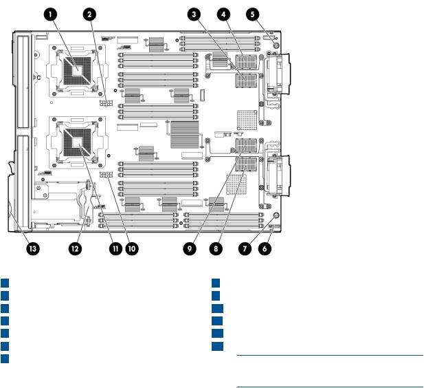
Server blade components
1 |
CPU0 |
8 |
ICH mezzanine connector |
2 |
CPU0 power connector |
9 |
Mezzanine connector 3 (type 1 or 2) |
3 |
Mezzanine connector 1 (type 1) |
10 |
CPU1 power connector |
4 |
Mezzanine connector 2 (type 1 or 2) |
11 |
CPU1 |
5 |
System board thumbscrew |
12 |
SAS backplane |
6 |
Battery (CR2032) |
13 |
Pull tab |
7 |
System board thumbscrew |
|
|
NOTE: The iLO 3 password is located on the pull tab.
Server blade components |
9 |

2 Site preparation
The HP Integrity BL860c i2 Server Blade does not have cooling or power systems. Cooling and power is provided by the c-Class enclosure.
IMPORTANT: To avoid hardware damage, allow the thermal mass of the product to equalize to the temperature and humidity of the installation facility after removing the shipping materials. A minimum of one hour per 10°C (18°F) of temperature difference between the shipping facility and installation facility is required
Server blade dimensions and weight
Table 1 Server blade dimensions and weight for the BL860c i2
Dimensions |
value |
Height |
36.63 cm (14.42 in.) |
Width |
5.14 cm (2.025 in.) |
Depth |
48.51 cm (19.1 in.) |
Weight |
Unloaded: 8.6 kg (19 lb) |
|
Fully loaded: 11.3 kg (25 lb) |
Table 2 Blade Link dimensions and weight
Blade Link type |
Height |
Width |
Weight |
SBL1 (BL860 i2) |
44 mm (1.73 in) |
51 mm (2 in) |
.5 lb (.22 kg) |
SBL2 (BL870 i2) |
44 mm (1.73 in) |
106 mm (4.17 in) |
1 lb (.45 kg) |
SBL4 (BL890 i2) |
44 mm (1.73 in) |
212 mm (8.34 in) |
2 lb (.90 kg) |
Enclosure information
All three blade configurations are supported in c7000 and c3000 Enclosures.
For more enclosure information see:
http://h71028.www7.hp.com/enterprise/cache/316735-0-0-0-121.html.
Enclosure environmental specifications
NOTE: This information is for both c3000 and c7000 Enclosures.
Specification |
Value |
Temperature range 1 |
|
Operating |
10°C to 35°C (50°F to 95°F) |
Non-operating |
-30°C to 60°C (-22°F to 140°F) |
Wet bulb temperature |
|
Operating |
28ºC (82.4ºF) |
Non-operating |
38.7ºC (101.7ºF) |
Relative humidity (noncondensing)2 |
|
10 Site preparation
Operating |
20% to 80% |
Non-operating |
5% to 95% |
1All temperature ratings shown are for sea level. An altitude derating of 1°C per 304.8 m (1.8°F per 1000 ft) to 3048 m (10,000 ft) is applicable. No direct sunlight allowed. Upper operating limit is 3,048 m (10,000 ft) or 70 Kpa/10.1 psia. Upper non-operating limit is 9,144 m (30,000 ft) or 30.3 KPa/4.4 psia.
2Storage maximum humidity of 95% is based on a maximum temperature of 45°C (113°F). Altitude maximum for storage corresponds to a pressure minimum of 70 KPa.
For more information on the c-Class enclosures, go to http://h71028.www7.hp.com/enterprise/ cache/316735-0-0-0-121.htmlf.
For more site preparation information, go to http://www.hp.com/go/Blades-docs, select HP Integrity BL860c i2 Server Blade in the list of servers, and then select the Generalized Site Preparation Guidelines.
Sample Site Inspection Checklist |
|
|
|
Table 3 Customer and HP Information |
|
|
|
Customer Information |
|
|
|
Name: |
|
Phone number: |
|
Street address: |
City or Town: |
|
|
State or province: |
Country |
|
|
Zip or postal code: |
|
|
|
Primary customer contact: |
Phone number: |
|
|
Secondary customer contact: |
Phone number: |
|
|
Traffic coordinator: |
Phone number: |
|
|
|
|
HP information |
|
Sales representative |
Order number: |
|
|
Representative making survey |
Date: |
|
|
Scheduled delivery date |
|
|
|
Table 4 Site Inspection Checklist |
|
|
|
Check either Yes or No. If No, include comment number or date. |
Comment or Date |
||
Computer Room |
|
|
|
Number |
Area or condition |
Yes |
No |
1. |
Is there a completed floor plan? |
|
|
2.Is adequate space available for maintenance needs? Front 36 inches (91.4 cm) minimum and rear 36 inches (91.4 cm) minimum are recommended clearances.
 3.
3.  Is access to the site or computer room restricted?
4.Is the computer room structurally complete? Expected date of completion?
 5.
5.  Is a raised floor installed and in good condition?
  6.
6.  Is the raised floor adequate for equipment loading?
  7.
7.  Are channels or cutouts available for cable routing?
Sample Site Inspection Checklist |
11 |

 Table 4 Site Inspection Checklist (continued)
Check either Yes or No. If No, include comment number or date. |
Comment or Date |
|
8. |
Is a network line available? |
|
9. |
Is a telephone line available? |
|
10.Are customer-supplied peripheral cables and LAN cables available and of the proper type?
 11.
11.  Are floor tiles in good condition and properly braced?
12.Is floor tile underside shiny or painted? If painted, judge the need for particulate test.
Power and Lighting |
|
|
Number |
Area or Condition |
Yes No |
13. |
Are lighting levels adequate for maintenance? |
|
14. Are AC outlets available for servicing needs (for example, laptop)?  15.
15.  Does the input voltage correspond to equipment specifications?
15a. Is dual source power used? If so, identify types and evaluate grounding.
 16.
16.  Does the input frequency correspond to equipment specifications?
17. Are lightning arrestors installed inside the building?
 18.
18.  Is power conditioning equipment installed? 19. Is a dedicated branch circuit available for equipment?
20. Is the dedicated branch circuit less than 75 feet (22.86 m)?
21. |
Are the input circuit breakers adequate for equipment loads? |
|
|
Safety |
|
|
|
Number |
Area or Condition |
Yes |
No |
22. Is an emergency power shutoff switch available?  23.
23.  Is a telephone available for emergency purposes?
24. Does the computer room have a fire protection system?  25.
25.  Does the computer room have antistatic flooring installed?
26.Do any equipment servicing hazards exist (loose ground wires, poor lighting, and so on)?
Cooling |
|
|
Number |
Area or Condition |
Yes No |
27.Can cooling be maintained between 5°C (41 °F) and 35°C (95 °F) (up to 1,525 m/5,000 ft)? Derate 1°C/305 m (34 °F/1,000 ft) above 1,525 m/5,000 ft and up to 3,048 m/10,000 ft.
28.Can temperature changes be held to 5°C (9 °F) per hour with tape media? Can temperature changes be held to 20°C (36 °F) per hour without tape media?
29.Can humidity level be maintained at 40% to 55% at 35°C (95 °F) noncondensing?
 30.
30.  Are air-conditioning filters installed and clean?
Storage
12 Site preparation

 Table 4 Site Inspection Checklist (continued)
Check either Yes or No. If No, include comment number or date. |
Comment or Date |
|
Number |
Area or Condition |
Yes No |
31. |
Are cabinets available for tape and disc media? |
|
32. |
Is shelving available for documentation? |
|
Training |
|
|
Number |
Area or Condition |
|
33. |
Are personnel enrolled in the System Administrator’s Course? |
|
34. |
Is on-site training required? |
|
Power subsystem
The power subsystem is located on the system board. The BL860c i2 Server Blade receives 12 Volts directly from the enclosure. The voltage is immediately passed through an E-fuse circuit, which will immediately cut power to the blade if a short circuit fault or over current condition is detected. The E-fuse can also be intentionally power cycled through the manageability subsystem. The 12V is distributed to various points on the blade and is converted to lower voltages through power converters for use by integrated circuits and loads on the blade.
ESD handling information
CAUTION: Wear an ESD wrist strap when handling internal server components. Acceptable ESD wrist straps include:
•The wrist strap that is included in the ESD kit with circuit checker (part number 9300-1609).
•The wrist strap that is included in the ESD kit without circuit checker (part number 9300-1608).
If the above options are unavailable, the throw away (one use only) strap that ships with some HP memory products can also be used, with increased risk of electrostatic damage.
When removing and replacing server components, use care to prevent injury and equipment damage. Many assemblies are sensitive to damage by electrostatic discharge.
Follow the safety precautions listed to ensure safe handling of components, to prevent injury, and to prevent damage to the server blade:
•When removing or installing a server blade or server blade component, review the instructions provided in this guide.
•Do not wear loose clothing that might snag or catch on the server or on other items.
•Do not wear clothing subject to static charge build-up, such as wool or synthetic materials.
•If installing an internal assembly, wear an antistatic wrist strap, and use a grounding mat such as those included in the Electrically Conductive Field Service Grounding Kit.
•Handle components by the edges only. Do not touch any metal-edge connectors or electrical components on accessory boards.
Unpacking and inspecting the server blade
Be sure that you have adequately prepared your environment for your new server blade, received the components that you ordered, and verified that the server and the containers are in good condition after shipment.
Power subsystem 13

Verifying site preparation
Verifying site preparation is an essential factor of a successful server blade installation, and includes the following tasks:
•Gather LAN information. Determine the two IP addresses for the iLO 3 MP LAN and the server blade LAN.
•Establish a method to connect to the server blade console. For more information on console connection methods, see “Using iLO 3” (page 25) for more information.
•Verify electrical requirements. Be sure that grounding specifications and power requirements are met.
•Confirm environmental requirements.
Inspect the shipping containers for damage
HP shipping containers protect their contents under normal shipping conditions. After the equipment arrives, carefully inspect each carton for signs of shipping damage. Shipping damage constitutes moderate to severe damage such as punctures in the corrugated carton, crushed boxes, or large dents. Normal wear or slight damage to the carton is not considered shipping damage. If you find shipping damage to the carton, contact your HP customer service representative immediately.
Unpacking the server blade
1.Use the instructions printed on the outside top flap of the carton.
2.Remove inner accessory cartons and the top foam cushions.
IMPORTANT: Inspect each carton for shipping damage as you unpack the server blade.
3.Place the server blade on an antistatic pad.
Verifying the inventory
The sales order packing slip lists the equipment shipped from HP. Use this packing slip to verify that the equipment has arrived.
NOTE: To identify each item by part number, see the sales order packing slip.
Returning damaged equipment
If the equipment is damaged, immediately contact your HP customer service representative. The service representative initiates appropriate action through the transport carrier or the factory and assists you in returning the equipment.
14 Site preparation
3 Installing the server blade into the enclosure
Installation sequence and checklist
Step |
Description |
Completed |
1 |
Perform site preparation (see “Site preparation” (page 10)for more information). |
|
2Unpack and inspect the server shipping container and then inventory the contents using the packing slip.
 3
3  Install additional components shipped with the server.
4 Install and power on the server blade.
 5
5  Configure iLO 3 MP access.
6 Access iLO 3 MP.
 7
7  Access UEFI from iLO 3 MP.
8 Download latest firmware using HP Smart Update Manager
 9
9  Install and boot the OS.
NOTE: For more information regarding HP Integrity Server Blade upgrades, see “Upgrading a conjoined configuration” (page 66)for more information.
Installing and powering on the server blade
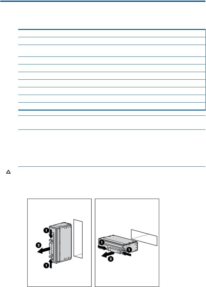
Preparing the enclosure
HP BladeSystem enclosures ship with device bay dividers to support half-height devices. To install a full height device, remove the blanks and the corresponding device bay divider.
CAUTION: To prevent improper cooling and thermal damage, do not operate the server blade or the enclosure unless all hard drive and device bays are populated with either a component or a blank.
1.Remove the device bay blank.
Installation sequence and checklist 15
2.Remove the three adjacent blanks.
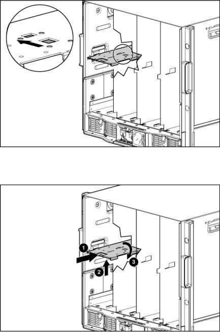
Removing a c7000 device bay divider
1.Slide the device bay shelf locking tab to the left to open it.
2.Push the device bay shelf back until it stops, lift the right side slightly to disengage the two tabs from the divider wall, and then rotate the right edge downward (clockwise).
16 Installing the server blade into the enclosure
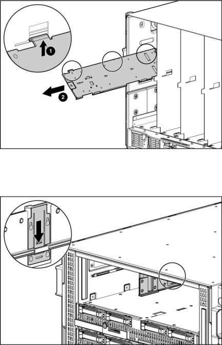
3.Lift the left side of the device bay shelf to disengage the three tabs from the divider wall, and then remove it from the enclosure.
Removing a c3000 device bay mini-divider or device bay divider
1.Slide the locking tab down.
Installing and powering on the server blade 17
2.Remove the mini-divider or divider:
•c3000 mini-divider:
Push the divider toward the back of the enclosure until the divider drops out of the enclosure.
•c3000 divider
a.Push the divider toward the back of the enclosure until it stops.
b.Slide the divider to the left to disengage the tabs from the wall.
c.Rotate the divider clockwise.
d.Remove the divider from the enclosure.
Installing interconnect modules
For specific steps to install interconnect modules, see the documentation that ships with the interconnect module.
18 Installing the server blade into the enclosure

Interconnect bay numbering and device mapping
•HP BladeSystem c7000 Enclosure
•HP BladeSystem c3000 Enclosure
To support network connections for specific signals, install an interconnect module in the bay corresponding to the embedded NIC or mezzanine signals.
Server blade signal |
c7000 interconnect bay |
c3000 interconnect bay |
Interconnect bay labels |
NIC 1 (Embedded) |
1 |
1 |
|
NIC 2 (Embedded) |
2 |
1 |
|
NIC 3 (Embedded) |
1 |
1 |
|
NIC 4 (Embedded) |
2 |
1 |
|
Mezzanine 1 |
3 and 4 |
2 |
|
Installing and powering on the server blade 19
Server blade signal |
c7000 interconnect bay |
c3000 interconnect bay |
Interconnect bay labels |
Mezzanine 2 |
5 and 6 |
3 and 4 |
|
|
7 and 8 |
3 and 4 |
|
Mezzanine 3 |
5 and 6 |
3 and 4 |
|
|
7 and 8 |
3 and 4 |
|
For detailed port mapping information, see the HP BladeSystem enclosure installation poster or the HP BladeSystem enclosure setup and installation guide for your product on the HP website (http://www.hp.com/go/bladesystem/documentation).
Installing the server blade into the enclosure
NOTE: When installing additional blades into an enclosure, additional power supplies might also be needed to meet power requirements. For more information, see the HP BladeSystem enclosure setup and installation guide for your product on the HP website (http://www.hp.com/ go/bladesystem/documentation).
NOTE: Before installing and initializing the server blade, install any server blade options, such as an additional processor, hard drive, or mezzanine card.
1.Remove the connector covers if they are present.
2.Prepare the server blade for installation.
20 Installing the server blade into the enclosure
3.Install the server blade.
The server blade should come up to standby power. The server blade is at standby power if the blade power LED is amber.
Server blade power states
The server blade has three power states: standby power, full power, and off. Install the server blade into the enclosure to achieve the standby power state. Server blades are set to power on to standby power when installed in a server blade enclosure. Verify the power state by viewing the LEDs on the front panel, and using Table 5.
For more front panel LED information, see “Front panel LEDs” (page 93).
Installing and powering on the server blade 21

Table 5 Power States
Power States |
Server Blade Installed |
Front Panel Power |
Standby Power |
DC Power Applied? |
|
in Enclosure? |
Button Activated? |
Applied? |
|
Standby power |
Yes |
No |
Yes |
No |
Full power |
Yes |
Yes |
Yes |
Yes |
Off |
No |
No |
No |
No |
Powering on the server blade
Use one of the following methods to power on the server blade:
NOTE: To power on blades in a conjoined configuration, only power on the Monarch blade.
•Use a virtual power button selection through iLO 3.
•Press and release the Monarch power button.
When the server blade goes from the standby mode to the full power mode, the blade power LED changes from amber to green.
For more information about iLO 3, see “Using iLO 3” (page 25).
Powering off the server blade
Before powering down the server blade for any upgrade or maintenance procedures, perform a backup of critical server data and programs.
Use one of the following methods to power off the server blade:
NOTE: To power off blades in a conjoined configuration, only power off the Monarch blade.
•Use a virtual power button selection through iLO 3 (Power Management, Power & Reset).
This method initiates a controlled remote shutdown of applications and the OS before the server blade enter standby mode.
•Press and release the Monarch power button.
This method initiates a controlled shutdown of applications and the OS before the server blade enter standby mode.
•Press and hold the Monarch power button for more than 4 seconds to force the server blade to enter standby mode.
This method forces the server blade to enter standby mode without properly exiting applications and the OS. It provides an emergency shutdown method in the event of a hung application.
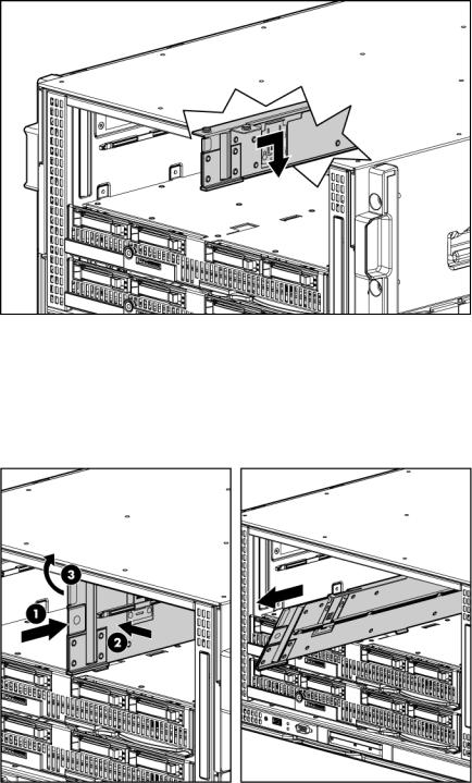
Installing the Blade Link for BL870c i2 or BL890c i2 configurations
IMPORTANT: Without an attached Blade Link, the server blades will not power on.
22 Installing the server blade into the enclosure

NOTE: Before installing the Blade Link for BL870c i2 or BL890c i2, make sure the following statements are true:
•All blades have the same CPU SKUs
•All blades have the same hardware revision (only use BL860c i2, BL870c i2, or BL890c i2 Server Blades)
•All blades have CPU0 installed
•All blades have the same firmware revision set
•All blades follow the memory loading rules for your configuration, see “DIMMs” (page 49)
•The enclosure OA firmware is compatible with the blade firmware
•The Monarch blade has an ICH mezzanine card installed
•The proper Blade Link is being used for your configuration
To check on the blade hardware revisions and CPU SKUs, go to the Command Menu in the iLO 3 TUI and enter the DF command. This dumps the FRU content of the blades.
NOTE: If you will be upgrading an initial installation, see “Upgrading a conjoined configuration” (page 66) for more information on server blade upgrades.
Blade Link bay location rules
|
|
Number of |
|
|
Partner |
Partner blade half-height bay |
|
Blade Link |
conjoined |
Supported |
|
blade |
number / Server blade |
Class |
part number |
blades |
enclosures |
Blade location rules |
support? |
full-height bay number |
BL1 |
AD399-67002 |
1 (standard for |
c7000 |
No specific bay |
Yes |
Bottom half-height adjacent |
|
|
BL860c i2) |
|
location rules for |
|
bay, paired with the server |
|
|
|
|
blades |
|
blade in full-height bays 1&2, |
|
|
|
|
|
|
3&4, 5&6, or 7&8 |
|
|
|
c3000 |
|
|
Half-height bay 8, paired with |
|
|
|
|
|
|
the server blade in full-height |
|
|
|
|
|
|
bay 3. |
|
|
|
|
|
|
CAUTION: The bay |
|
|
|
|
|
|
mini-divider must be installed |
|
|
|
|
|
|
in the c3000 enclosure to |
|
|
|
|
|
|
ensure the partner blade is |
|
|
|
|
|
|
inserted correctly. Failure to |
|
|
|
|
|
|
install the bay mini-divider |
|
|
|
|
|
|
might result in damage to the |
|
|
|
|
|
|
blade or enclosure when |
|
|
|
|
|
|
installing the partner blade.1 |
BL2 |
AD399-67003 |
2 (BL870c i2) |
c7000 |
Bays 1&2, 3&4, |
No |
N/A |
|
|
|
|
5&6, or 7&8 with |
|
|
|
|
|
|
Monarch blade in |
|
|
|
|
|
|
odd bay |
|
|
|
|
|
c3000 |
Bays 1&2, 3&4 with |
|
|
|
|
|
|
Monarch blade in |
|
|
|
|
|
|
odd bay |
|
|
BL2E |
AD399-67010 |
2 (BL870c i2) |
c7000 only |
Bays 2&3, 4&5 or |
Yes |
Bottom half-height bay 9 |
|
|
|
|
6&7 with Monarch |
|
paired with full-height bays |
|
|
|
|
blade in even bay |
|
2&3, bottom half-height bay |
|
|
|
|
using full-height |
|
11 paired with full-height bays |
|
|
|
|
numbering |
|
4&5, bottom half-height bay |
|
|
|
|
|
|
13 paired with full-height bays |
|
|
|
|
|
|
6&7 |
Installing the Blade Link for BL870c i2 or BL890c i2 configurations 23

|
|
Number of |
|
|
Partner |
Partner blade half-height bay |
|
Blade Link |
conjoined |
Supported |
|
blade |
number / Server blade |
Class |
part number |
blades |
enclosures |
Blade location rules |
support? |
full-height bay number |
|
AD399-67011 |
2 (BL870c i2) |
c3000 only |
Bays 2&3 with |
No |
N/A |
|
|
|
|
Monarch blade in |
|
|
|
|
|
|
even bay using |
|
|
|
|
|
|
full-height numbering. |
|
|
BL4 |
AD399-67006 |
4 (BL890c i2) |
c7000 only |
Bays 1&2&3&4 or |
No |
N/A |
|
|
|
|
5&6&7&8, with |
|
|
|
|
|
|
Monarch blade |
|
|
|
|
|
|
defaulting to slot 1 or |
|
|
|
|
|
|
slot 5, respectively |
|
|
|
AD399-67007 |
4 (BL890c i2) |
c3000 only |
Bays 1&2&3&4 with |
No |
N/A |
|
|
|
|
Monarch blade |
|
|
|
|
|
|
defaulting to slot 1 |
|
|
1For information on installing the c3000 bay mini-divider, see the HP BladeSystem c3000 Enclosure Setup and Installation Guide.
CAUTION: Using the incorrect Blade Link can cause damage to the Blade Link and to the connectors on both the Blade Link and the server blades.
IMPORTANT: Failure to follow bay location rules can prevent server blade power on.
NOTE: The manufacturing part numbers for the Blade Link is located on a sticker on the PCA.
“Upgrading a conjoined configuration” (page 66)
To install the Blade Link:
1.Log on to the OA.
2.Install the first blade into the lowest bay number, this blade becomes the Monarch blade (“Installing the server blade into the enclosure”).
3.Wait 10 seconds. The IP address of the installed blade appears in the OA.
4.Insert each adjacent blade, waiting 10 seconds between blades.
NOTE: The blades will go into stand-by
5.Using the OA, verify that the rest of the blades that will be conjoined have an IP address and are powered off.
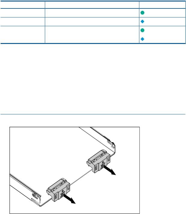
6.Remove the plastic protectors from the connectors on the back of the Blade Link.
7.Push in the blue release latch on the handle to release the handle.
8.Pull the handle all the way out
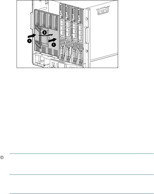
9.Align the guide pins on the back of the Blade Link to the holes on the front of the server blades. As you insert the pins into the holes, ensure the face on the Blade Link is evenly aligned parallel to the face of the server blades.
10.Press firmly on the left and right sides of the Blade Link face until the handle naturally starts to close.
CAUTION: If not properly aligned, you can damage the Blade Link
11. Close the handle when it has engaged.
24 Installing the server blade into the enclosure
12.Log into iLO 3 on the Monarch blade. For more information, see the HP Integrity iLO3 Operations Guide.
13.In iLO 3, go to the Command Menu and execute xd -r to reboot all of the iLO 3s in the conjoined set.
14.Still in the iLO 3 Command Menu, power on the Monarch blade with the PC -on -nc command. Powering on the Monarch blade will power the entire conjoined system on.
15.Boot the Monarch blade. Booting the Monarch blade boots the entire conjoined system.
Conjoin checks
Integrity BL870c i2 and BL890c i2 systems go through a process called “conjoining” when the Blade Link is attached. The system cannot boot until that process is completed properly. The following CM commands in the iLO 3 TUI show data from all blades, and can be used to determine if the blades are successfully conjoined:
•DF— Lists the FRUs on all of the blades (2 or 4).
•SR — Shows a table of each blades firmware revisions.
•Blade— Shows information about the OA and the bays used. The OA will also show a properly conjoined system from its GUI.
IMPORTANT: The secondary UUID and other system variables are stored on the Monarch blade. If you do not put the Monarch blade in the leftmost slot, your system variables will not match. If you ever change your iLO 3 configuration (such as adding users) that data is also stored on the Monarch blade.
NOTE: Auxiliary blades are not slot dependent after being installed and configured, however when the conjoined systems ship, they come with A, B, C, D stickers located under the Blade Links. While auxiliary blades are not slot dependent after being installed and configured, HP recommends using the shipped order to ensure proper auxiliary blade function.
Using iLO 3
The iLO 3 subsystem is a standard component of selected server blades that provides blade health and remote server manageability. The iLO 3 subsystem includes an intelligent microprocessor, secure memory, and a dedicated network interface. This design makes iLO 3 independent of the host server and operating system. The iLO 3 subsystem provides remote access to any authorized network client, sends alerts, and provides other server management functions.
Using iLO 3 25

Using iLO 3, you can:
•Remotely power on, power off, or reboot the host server.
•Send alerts from iLO 3 regardless of the state of the host server.
•Access advanced troubleshooting features through the iLO 3 interface.
For more information about iLO 3 basic features, see the iLO 3 documentation on the HP website (http://www.hp.com/servers/lights-out).
Accessing UEFI or the OS from iLO 3 MP
UEFI is an architecture that provides an interface between the server blade OS and the server blade firmware. UEFI provides a standard environment for booting an OS and running preboot applications.
Use this procedure to access UEFI or the OS from the iLO 3 MP. Your security parameters were set regarding remote access.
1.Retrieve the factory iLO 3 password from the iLO 3 Network pull tab located on the right side of the Monarch blade.
2.From the MP Main Menu, enter co to access the Console.
NOTE: Terminal windows should be set to a window size of 80 columns x 25 rows for optimal viewing of the console at UEFI.
3.After memory test and CPU late self test the following message appears:
Press Ctrl-C now to bypass loading option ROM UEFI drivers.
The prompt will timeout if Ctrl-C is not pressed within a few seconds. If Ctrl-C is pressed, you will be presented with two options:
•Bypass loading from I/O slots.
•Bypass loading from I/O slots and core I/O.
The Bypass loading from I/O slots and core I/O option may be useful if a bad core I/O UEFI driver is preventing system boot. USB drives can still be used at the UEFI shell to update core I/O drivers.
CAUTION: Hitting Ctrl-C before the prompt will not work and may even disable this feature, be sure wait for the prompt before hitting Ctrl-C.
NOTE: It can take several minutes for this prompt to appear, and the window of time when Ctrl-C can be pressed is very short. For typical boots, HP recommends that you let the prompt time out.
After selecting an option, boot will proceed.
NOTE: If no option is selected, normal boot will proceed after ten seconds.
4.Depending on how the server blade was configured from the factory, and if the OS is installed at the time of purchase, you are taken to:
•UEFI shell prompt
•OS login prompt
If the server blade has a factory-installed OS, you can interrupt the boot process to configure your specific UEFI parameters.
If you are at the UEFI shell prompt, go to “UEFI Front Page” (page 27).
If you are at the OS login prompt, go to “OS login prompt” (page 29).
26 Installing the server blade into the enclosure
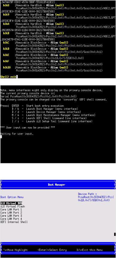
UEFI Front Page
If you are at the UEFI shell prompt, enter exit to get to the UEFI Front Page.
To view boot options, or launch a specific boot option, press B or b to launch the Boot Manager.
Accessing UEFI or the OS from iLO 3 MP 27
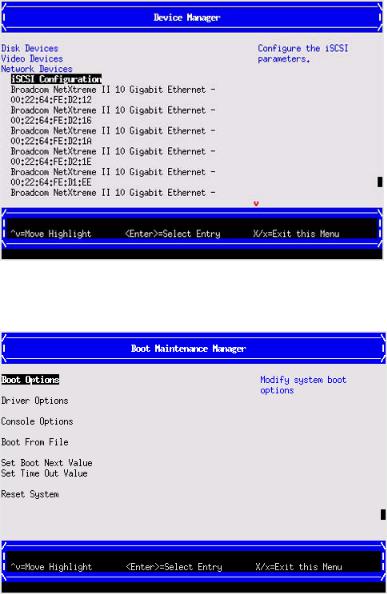
To configure specific devices, press D or d to launch the Device Manager. This is an advanced feature and should only be performed when directed.
To perform maintenance on the system such as adding, deleting, or reordering boot options, press M or m to launch the Boot Maintenance Manager.
To perform more advanced operations, press S or s to launch the UEFI Shell.
To view the iLO 3 LAN configuration, press I or i to launch the iLO 3 Setup Tool.
Saving UEFI configuration settings
There are other UEFI settings you can configure at this time. For more UEFI configuration options, see Appendix A (page 133).
Booting and installing the operating system
From the UEFI Front Page prompt, you can boot and install in either of two manners:
•If your OS is loaded onto your server blade, see “Operating system is loaded onto the server blade” (page 29).
•If the OS is not installed onto your server blade, see “Operating system is not loaded onto the server blade” (page 29).
28 Installing the server blade into the enclosure
Operating system is loaded onto the server blade
If the OS is loaded on your server blade, normally UEFI will automatically boot to the OS. If the UEFI Front Page is loaded, press ENTER to start auto boot, or B or b to select a specific boot option for your OS.
•Use your standard OS logon procedures, or see your OS documentation to log on to your OS.
Operating system is not loaded onto the server blade
There are two options on how to load the OS if it is not loaded onto your server blade.
•To load the OS from a DVD, see “Installing the OS from an external USB DVD device or tape device” (page 30).
•To load the OS using Ignite-UX, see “Installing the OS using HP Ignite-UX” (page 31).
OS login prompt
If your server blade is at the OS login prompt after you establish a connection to the server blade, use your standard OS log in procedures, or see your OS documentation for the next steps.
Installing the latest firmware using HP Smart Update Manager
The HP Smart Update Manager utility enables you to deploy firmware components from either an easy-to-use interface or a command line. It has an integrated hardware discovery engine that discovers the installed hardware and the current versions of firmware in use on target servers. This prevents extraneous network traffic by only sending the required components to the target. HP Smart Update Manager also has logic to install updates in the correct order and ensure all dependencies are met before deployment of a firmware update. It also contains logic to prevent version-based dependencies from destroying an installation and ensures updates are handled in a manner that reduces any downtime required for the update process. HP Smart Update Manager does not require an agent for remote installations.
Key features of HP Smart Update Manager are:
•GUI and CLI–command line interface
•Dependency checking, which ensures appropriate installation order and dependency checking between components
•Intelligent deployment deploys only required updates
•Improved deployment performance
•Remote command-line deployment
•Windows X86 or Linux X86 support
At this time, firmware updates on Integrity systems through HPSUM are done remotely. For example, HP SUM runs on an x86 Linux or Windows management system and updates targeted Integrity systems through the network. HP Smart Update Manager supports firmware updates on the BL860c i2, BL870c i2, and BL890c i2 servers. Firmware bundles for these servers are available and can be downloaded from the HP website at http://www.hp.com.
For more information about HP Smart Update Manager, see the HP Smart Update Manager User Guide (http://www.hp.com/go/hpsum/documentation).
Installing the latest firmware using HP Smart Update Manager 29

4 Operating system procedures
Operating systems supported on the server blade
•HP-UX 11i v3 HWE 1003
•HP OpenVMS v8.4
•Microsoft Windows Server 2008 Itanium Edition R2
Installing the operating system onto the server blade
The following procedures describe generalized operating system installation. For more details, see the operating system documentation.
Installing the OS from an external USB DVD device or tape device
NOTE: Tapeboot requires BL8x0c i2 system firmware bundle 26.11 or later and a partner tape blade, or an additional 51378-B21 Integrity Smart Array P711m HBA running 6.22 firmware or later to boot from an Ultrium 6250 tape drive.
1.If using an external USB DVD device:
a.Connect the Integrity SUV cable to the front of the Monarch server blade.
b.Connect the USB DVD cable to one of the USB ports on the SUV cable.
NOTE: Some DVD drives might also require a separate power connection.
c.Turn on the external USB DVD device.
2.Insert the OS media into the USB DVD device or tape device.
3.Power on the server blade and boot to UEFI. If the server blade is already powered on, then reboot to UEFI using the reset command at the UEFI prompt.
4.From the UEFI Front Page, press S or s to launch the UEFI Shell.
NOTE: If the device is already selected or you already know the device name, then skip the following step.
If you are using a tape device, when the UEFI shell comes up, you should see a message similar to the following on the console:
HP Smart Array |
P212 Controller |
(version 6.22) |
|
Tape Drive(s) Detected: |
|
|
|
Port: 1I, |
box:0, bay: 3 |
(SAS) |
|
The message may also be similar to the following.
HP Smart Array |
P711m Controller |
(version 6.22) 0 Logical Drives |
|
Tape Drive(s) Detected: |
|
|
|
Port: 2E, |
box:1, bay: 9 |
(SAS) |
|
NOTE: If you do not see a line starting with Port and ending with (SAS), the tape is not connected correctly or it is not responding.
30 Operating system procedures
Loading...