


HP 706A, 708F, 710F, 708C, 706E User Manual
...OWNER'S MANUAL
__________________
PRINT MASTER 700 SERIES
PRINTER CONTROLLERS
706A
706C
708C
710C
706D
708D
706E
708E
710E
708F
710F
BayTech publication #U140E045-05
Dear Customer,
Thank you for selecting a BayTech Print Master printer controller.
The data provided in this Owner's Manual explains the various ways you can operate your unit and configure it to your own computer system. We suggest that you read this manual carefully before attempting to install Print Master and that you place special emphasis on correct cabling and configuration. If you have any problems with your installation, please contact a BayTech applications engineer for assistance.
BayTech also manufactures data communications devices that provide port sharing and expansion, networking, port contention, buffered and non-buffered printer sharing, and multiplexing. If you would like information on any of these models, please contact
BayTech Customer Service.
We welcome any comments you may have about our products. And we hope that you will continue to look to BayTech for your data communications needs.
The information contained in this document is subject to change without notice.
Copyright 1993 by Bay Technical Associates, Inc.
IBM PC, IBM PC/AT, IBM PC/XT and IBM PS/2 are products of International Business Machines Corporation.
Hewlett-Packard LaserJet is a product of the Hewlett-Packard
Company.
Wordperfect is a product of Wordperfect, Inc.
WordStar is a registered trademark of MicroPro International Corp. Windows is a registered trademark of Microsoft Corp.
Print Master is a registered trademark of Bay Technical Associates,
Inc.
TABLE OF CONTENTS
1 |
GENERAL INFORMATION............................................... |
1 |
|
2 |
SPECIFICATIONS ............................................................ |
3 |
|
3 |
QUICK REFERENCE ....................................................... |
6 |
|
4 |
INSTALLATION .............................................................. |
10 |
|
|
4.1 |
UNPACKING........................................................ |
10 |
|
4.2 |
SOFTWARE UTILITY DISKETTE........................ |
10 |
|
4.3 |
POWER ............................................................... |
12 |
|
4.4 |
FACTORY DEFAULTS ........................................ |
12 |
|
4.5 |
PC SET-UP .......................................................... |
13 |
5 |
CABLING ........................................................................ |
15 |
|
|
5.1 |
PARALLEL PORTS.............................................. |
15 |
|
5.2 |
SERIAL PORTS ................................................... |
16 |
5.3PRINT MASTER MODELS 706C, 708C AND
710C WITH RJ-45 MODULAR CONNECTORS .. 19
6 |
OPERATION................................................................... |
20 |
|
6.1 USER-PROGRAMMABLE CONFIGURATIONS .. 20 |
|
|
6.1.1 THE PORT LOGICAL NAME .................... |
20 |
|
6.1.2 THE NUMBER OF PRINTERS/THE PORT |
|
|
ASSIGNMENT........................................... |
21 |
|
6.1.3 THE PRINTER SELECT CODE ................ |
22 |
|
6.1.4 THE PRINTER SELECT MODE................ |
22 |
|
6.1.5 THE SERIAL PORT CONFIGURATION ... |
23 |
|
6.1.6 THE INPUT INACTIVITY TIMEOUT.......... |
23 |
|
6.1.7 THE FORM FEED MODE ......................... |
23 |
|
6.1.8 THE HEADER PAGE MESSAGE.............. |
24 |
6.2PRINTER SHARING OPERATING PROCEDURE 24
|
|
6.2.1 SHARING A SINGLE PRINTER................ |
25 |
|
|
|
6.2.2 SPECIFIED SHARING OF MULTIPLE |
|
|
|
|
|
PRINTERS ................................................ |
26 |
|
|
6.2.3 |
CONTENDING FOR MULTIPLE |
|
|
|
|
PRINTERS ................................................ |
27 |
|
|
6.2.4 BUFFERING OF PRINT DATA ................. |
28 |
|
|
|
6.2.5 |
BEGINNING AND ENDING A PRINT JOB 28 |
|
|
|
6.2.6 |
BUFFER CLEARING................................. |
30 |
|
|
6.2.7 MINIMUM SIZE PRINT JOB...................... |
30 |
|
|
|
6.2.8 |
PORT SELECTION METHODS ................ |
31 |
|
|
6.2.9 |
FULL DUPLEX COMMUNICATION .......... |
32 |
|
|
6.2.10 PLOTTER SHARING HINTS..................... |
32 |
|
|
6.3 |
LED INDICATORS ............................................... |
33 |
|
|
6.4 |
DATA FLOW CONTROL...................................... |
34 |
|
|
|
6.4.1 |
HARDWARE HANDSHAKING .................. |
34 |
|
|
6.4.2 |
XON/XOFF HANDSHAKING ..................... |
36 |
|
|
6.4.3 |
HP 3000 OPTION...................................... |
37 |
7 |
CONFIGURATION.......................................................... |
38 |
||
7.1MODELS 706A AND 708A - CONFIGURATION
PROCEDURE ...................................................... |
38 |
7.1.1 MODELS 706A AND 708A - MAIN |
|
CONFIGURATION MENU......................... |
40 |
7.1.2 MODELS 706A AND 708A - STATUS....... |
41 |
7.1.3 MODELS 706A AND 708A - CHANGE |
|
LOGICAL NAME........................................ |
42 |
7.1.4 MODELS 706A AND 708A - SET INPUT |
|
INACTIVITY TIMEOUT.............................. |
43 |
7.1.5 MODELS 706A AND 708A - SET |
|
NUMBER OF PRINTERS.......................... |
44 |
7.1.6 MODELS 706A AND 708A |
- PROGRAM |
|
PRINTER SELECT CODE |
........................ |
45 |
7.1.7 MODELS 706A AND 708A |
- SET |
|
PRINTER SELECT MODE |
........................ |
46 |
7.1.8 MODELS 706A AND 708A |
- SET FORM |
|
FEED MODE ............................................. |
|
46 |
7.1.9 MODELS 706A AND 708A |
- PROGRAM |
|
HEADER PAGE MESSAGE...................... |
47 |
|
7.1.10 MODELS 706A AND 708A .............- EXIT |
47 |
|
7.2ALL 700C MODELS - CONFIGURATION
PROCEDURE ...................................................... |
48 |
7.2.1 ALL 700C MODELS - MAIN |
|
CONFIGURATION MENU......................... |
50 |
7.2.2 ALL 700C MODELS - STATUS ................. |
51 |
7.2.3 ALL 700C MODELS - SET SERIAL PORT |
|
CONFIGURATION .................................... |
52 |
7.2.4 ALL 700C MODELS - SET INPUT |
|
INACTIVITY TIMEOUT.............................. |
55 |
7.2.5 ALL 700C MODELS - SET NUMBER OF |
|
PRINTERS ................................................ |
56 |
7.2.6 ALL 700C MODELS - PROGRAM |
|
PRINTER SELECT CODE ........................ |
57 |
7.2.7 ALL 700C MODELS - SET PRINTER |
|
SELECT MODE......................................... |
58 |
7.2.8 ALL 700C MODELS - SET FORM FEED |
|
MODE........................................................ |
58 |
7.2.9 ALL 700C MODELS - PROGRAM |
|
HEADER PAGE MESSAGE...................... |
59 |
7.2.10 ALL 700C MODELS - EXIT ....................... |
59 |
|
7.3 ALL 700D, 700E, 700F MODELS - |
|
||
|
CONFIGURATION PROCEDURE ....................... |
60 |
||
|
7.3.1 |
ALL 700D, 700E, |
700F MODELS - MAIN |
|
|
|
CONFIGURATION MENU......................... |
62 |
|
|
7.3.2 |
ALL 700D, 700E, |
700F MODELS - |
|
|
|
STATUS .................................................... |
|
63 |
|
7.3.3 |
ALL 700D, 700E, |
700F MODELS -SET |
|
|
|
SERIAL PORT CONFIGURATION............ |
64 |
|
|
7.3.4 |
ALL 700D, 700E, |
700F MODELS |
|
|
|
-CHANGE PORT LOGICAL NAME ........... |
67 |
|
|
7.3.5 |
ALL 700D, 700E, |
700F MODELS - SET |
|
|
|
PORT ASSIGNMENT................................ |
68 |
|
|
7.3.6 |
ALL 700D, 700E, |
700F MODELS -SET |
|
|
|
INPUT INACTIVITY TIMEOUT.................. |
70 |
|
|
7.3.7 |
ALL 700D, 700E, |
700F MODELS |
|
|
|
-PROGRAM PRINTER SELECT CODE.... |
71 |
|
|
7.3.8 |
ALL 700D, 700E, |
700F MODELS - SET |
|
|
|
PRINTER SELECT MODE ........................ |
72 |
|
|
7.3.9 |
ALL 700D, 700E, |
700F MODELS - SET |
|
|
|
FORM FEED MODE.................................. |
72 |
|
|
7.3.10 ALL 700D, 700E, |
700F MODELS - |
|
|
|
|
PROGRAM HEADER PAGE MESSAGE .. |
73 |
|
|
7.3.11 ALL 700D, 700E, |
700F MODELS - EXIT .. |
73 |
|
8 |
MAINTENANCE.............................................................. |
|
74 |
|
9 |
REPACKING FOR SHIPPING ........................................ |
|
74 |
|
10 |
TECHNICAL SUPPORT ................................................. |
|
75 |
|
11 FEDERAL COMMUNICATIONS COMMISSION RADIO |
|
|||
|
FREQUENCY INTERFACE STATEMENT ..................... |
77 |
||
APPENDIX A |
|
|
RECOMMENDED CABLING ......................................... |
78 |
|
A.1 |
BETWEEN IBM PC, IBM XT, IBM PS/2 |
|
|
AND PRINT MASTER (DB-25) ............................ |
78 |
A.2 |
BETWEEN IBM AT AND PRINT MASTER |
|
|
(DE-9)................................................................... |
80 |
A.3 |
BETWEEN PRINT MASTER AND |
|
|
HEWLETT PACKARD LASERJET ...................... |
82 |
A.4 |
BETWEEN PRINT MASTER AND |
|
|
ANY CENTRONICS PRINTER ............................ |
83 |
A.5 |
700C MODELS - MODULAR CABLING............... |
84 |
APPENDIX B |
|
|
OPTION 19 - CASCADE FEATURE FOR MODELS 710C, |
||
710E, 710F ..................................................................... |
86 |
|
B.1 |
OPTION 19 - CONFIGURATION ......................... |
87 |
|
B.1.1 OPTION 19 - MAIN CONFIGURATION |
|
|
MENU........................................................ |
88 |
|
B.1.2 OPTION 19 - CONFIGURATION STATUS 89 |
|
|
B.1.3 OPTION 19 - SET UNIT ID NUMBER ....... |
90 |
B.2 |
OPTION 19 - CABLING ....................................... |
91 |
B.3 |
OPTION 19 - SHARING OF PRINTERS.............. |
91 |
APPENDIX C |
|
|
TROUBLESHOOTING.................................................... |
93 |
|
APPENDIX D |
|
|
INDEX........................................................................... |
102 |
|
The BayTech 700 Series Print Master is a flexible, intelligent device that connects between your computers and peripherals allowing the computers to share the peripherals, including expensive plotters and laser printers. All models come in a self-contained desk-top unit or with a rack mount.
Print Master comes standard with a 1 MB buffer which is optionally available up to 2 MB. The built-in buffer saves valuable computer time by spooling data until the printer or plotter can receive it, keeping the computers working full time instead of waiting.
Print Master models are available with full duplex EIA-232 serial ports and/or Centronics compatible parallel ports depending upon the model purchased. The available serial/parallel port combination are listed below by model.
Model 706A has six parallel ports.
Model 708A has six parallel ports.
Model 706C has six serial ports.
Model 708C has eight serial ports.
Model 710C has ten serial ports.
Model 706D has four parallel and two serial ports.
Model 708D has six parallel and two serial ports.
Model 706E has four serial and two parallel ports.
Model 708E has six serial and two parallel ports.
Model 710E has eight serial and two parallel ports.
Model 708F has four serial and four parallel ports.
Model 710F has six serial and four parallel ports.
On models with combination serial and parallel ports, you may set up Print Master with parallel or serial in and parallel or serial out. Print Master internally converts data from serial-to-parallel or parallel-to-serial. Ports are user-configurable as computer ports or printer ports.
1
In addition to port assignment, you may program the following features to meet the need of your application: the individual serial port configuration (baud rate, word size, stop bits, parity, and XON/XOFF), the Port Logical Names, the Input Inactivity Timeout, the Printer Select Code, the Printer Select Mode, the Form Feed Mode, and the Header Page Message. Programming of these features is easily accomplished via the menu-driven configuration mode, and all changes are saved in non-volatile memory.
NOTE: Users of IBM compatible computers may utilize the BayTech Print Master Support Software Diskette supplied with the unit. Refer to Section 4.2 for instructions.
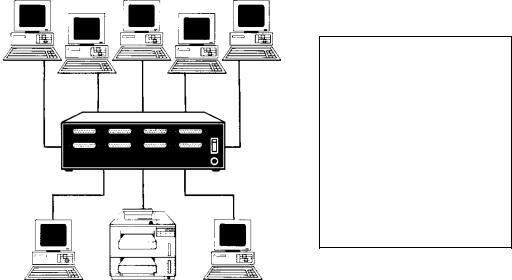
A typical application using Print Master would allow various computers
(e.g., PCs, main frames, mini computers, etc.) to share printers and/or plotters. For example, Figure 1 below shows seven PCs sharing a single HP LaserJet IIISi printer. This application would allow all the PCs to send print jobs to the printer simultaneously.
This application demonstrates just one on the many Print Master configuration possibilities. Print Master ports are programmable as computer or printer ports
Figure 1
2
INTERFACE:
Serial ports: Asynchronous EIA-232C (CCITT V.24), -12v mark, +12v space. Full duplex communication.
Parallel ports: Centronics protocol.
TRANSMISSION: Serial ports - asynchronous; full duplex communication;
Parallel ports - maximum 30,000 characters per second on the 706A and 708A. Up to 5000 characters per second on all other models.
STANDARD FACTORY-SET POWER-UP DEFAULT CONFIGURATION:
Serial ports:
Baud rate: 9600. Word size: 8. Stop bits: 1. Parity: None. XON/XOFF: Off.
Logical name: Device A to J.
Input inactivity timeout: 20 seconds.
Port assignment: Port 1 - printer port. All other ports - computer ports.
Printer Select Code: $PRINTER.
Printer Select Mode: 2 (Anytime while printing). Form feed mode: 1 (no form feed).
Header Page Message: Off. "This print job is for:".
3
USER-PROGRAMMABLE CONFIGURATION:
Reconfigurable in menu-driven mode through configuration port. Saved in non-volatile memory to become the new power-up default configuration.
Serial ports:
Baud rate: 110, 135, 300, 600, 1200, 2400, 4800, 9600, 19200. Other rates optional.
Word size: 5, 6, 7 or 8 bits.
Parity: Even, odd or none. Stop bits: 1, 1 1/2 or 2.
XON/XOFF: On or off. Port logical name: 16 characters.
Input inactivity timeout: 1 to 200 seconds or no timeout.
Port assignment: Any port user-set as computer or printer port with a minimum of one printer port and one computer port.
Printer Select Code: 1 to 8 ASCII characters.
Printer Select Mode:
Mode 1 = printer selection at beginning of printing;
Mode 2 = printer selection any time while printing.
Form feed mode: Mode 1 = no form feed;
Mode 2 = at beginning of printing; Mode 3 = at end of printing;
Mode 4 = at beginning and end of printing.
Header Page Message: 80 characters.
MINIMUM SIZE PRINT JOB: 3 characters.
INTERNAL BUFFER: 1 MB standard. All models available with 1.5 MB or 2 MB except the 706A and 708A. 706A and 708A models are available with 2 MB, 3 MB, or 4
MB.
4
POWER: 115 VAC, 50/60 Hz., .3A.
Optional 230 VAC, 50/60 Hz., .2A.
ENVIRONMENT: 0 degrees to 55 degrees C temperature;
5% to 95% humidity.
DIMENSIONS: 10 1/8w x 8d x 3h inches.
WEIGHT: 6 pounds.
INDICATORS: 1 green power LED; 6, 8 or 10 red, port-activity LEDs.
CONNECTORS: Shielded on all ports.
Serial ports - DB-25 female DCE connectors.
Parallel ports - DB-25 female connectors.
RJ-45 connectors available on the 706C, 708C, and
710C.
HANDSHAKING: Parallel ports - Busy (pin 11).
Serial ports - CTS/DTR and selectable XON/XOFF.
MOUNTING: Desk-top; rack-mount optional.
WARRANTY: One year parts and labor.
5

This section provides basic set up instructions for those knowledgeable in computer equipment installation. We will refer to specific sections in this manual for more in-depth instructions on installation operation, and configuration. Please review the following procedure:
Step |
Instructions |
|
|
1Determine what model Print Master you are installing. The model number is written on the front panel as shown below for the model 708A.
BayTech
Printer Controller
Print Master 708A
POWER |
1 |
2 |
3 |
4 |
5 |
6 |
7 |
8 |
FRONT VIEW
Print Master Model 708A
Identify which ports are serial and which are parallel. Ports are marked as serial or parallel on the back panel as shown below for the model 708E.
PARALLEL 1 |
SERIAL 2 |
SERIAL 3 |
SERIAL 4 |
115 VAC |
|
|
|
|
50/60 Hz. |
|
|
|
|
0.3 A |
|
|
|
|
ON |
PARALLEL 5 |
SERIAL 6 |
SERIAL 7 |
SERIAL 8 |
|
426761
Made In USA
Print Master II Model 708E
Determine what devices will connect to your Print Master and whether they will connect in serial or parallel. Typical devices include computers, printers, and plotters.
2PORT DESIGNATION
Determine which serial or parallel ports on Print Master will be assigned as computer or printer. Computers connect to ports assigned as computer. Printers and plotters
6

Step |
Instructions |
|
|
connect to ports assigned as printer. All ports are flexible except as noted below (i.e., ports may be configured as computer or printer). The standard factory default powerup configuration follows:
706A & 706C: Port 6 - computer port (host) * Port 1 - printer port *
Ports 2 through 5 - computer ports
706D & 706E: Port 6 - computer port (host) Port 1 - printer port
Ports 2 through 5 - computer ports
708A & 708C: Port 8 - computer port (host) * Port 1 - printer port *
Ports 2 through 7 - computer ports
708D, 708E, & 708F: Port 8 - computer port (host) Port 1 - printer port
Ports 2 through 7 - computer ports
710C: Port 10 - computer port (host) * Port 1 - printer port *
Ports 2 through 9 - computer ports
710E & 710F: Port 10 - computer port (host) Port 1 - printer port
Ports 2 through 9 - computer ports
If your application requires port assignments that are different from the factory default configuration, you must reconfigure your unit. Step 5 discusses configuration mode.
NOTE: If your application requires sharing more than one printer or plotter, you will have to reconfigure the port assignment(s) of your unit.
* Ports are fixed as computer or printer (i.e., cannot be changed).
3SERIAL PORT CONFIGURATION
NOTE: This step does not apply to the 706A and 708A models.
The serial port configuration of your serial devices and Print Master must all match. Print Master's default configuration follows:
Baud Rate: 9600 bps
Word Size: 8 bits
Stop Bits: 1 bit
Parity: None
XON/XOFF: Off
If you will be connecting any serial devices which communicate with serial parameters different than the default configuration, you must access configuration mode and make the appropriate changes. Step 5 discusses configuration mode.
4CABLING
Correct cables for the serial and parallel ports are vital for error free operation.
7

Step |
Instructions |
|
|
A. Serial Ports
Serial ports on Print Master are DCE. Therefore, straight cabling is required between the computer's serial port and Print Master's serial port. A straight cable is also required between Print Master's serial port and the serial port of a printer or plotter.
B. Parallel Ports
A straight through 25 pin parallel DB-25 male to DB-25 male cable is required to connect the parallel port of a computer to a parallel port of Print Master. A standard DB-25 male to centronics printer cable is required to connect the printer or plotter's parallel port to the parallel port of Print Master.
Please see Appendix A of this manual for more cabling information.
5CONFIGURATION MODE
If you need to access configuration mode to change the port assignment or serial port configuration (see Steps 2 and 3 respectively), please see Section 7 of this manual for instructions. If not, there is no need to access configuration mode.
NOTE: The easiest way to access configuration mode is to use the supplied utility created by running the INSTALL program as described in Section 4.2. This utility is TERM.EXE for all models other than the 706A and 708A. The utility for the 706A and 708A models is PARSEND.EXE.
6PORT SELECTION
NOTE: If you will have only one printer or plotter connected, you may skip this step.
You must select a printer port in multiple printer applications. The recommended methods to send the Port Select Code are:
A.TSR - Select a port from a menu in the memory resident program using hot keys. See
the README file generated by running the INSTALL program on the BayTech software utility diskette. When you run INSTALL, a menu titled "Printer Selection Programs" will appear on your screen. You are given three selections: RAMEXEC, RAMTSR, and WNDEXEC. Choose RAMEXEC if your PC runs non-Windows programs that do not operate in graphics mode. Choose RAMTSR if your PC runs non-Windows programs that operate in graphics mode. Choose WNDEXEC if your PC runs under Windows.
B.Physically insert the Port Select Code as the first characters of the text or data in
the
document. See Section 6.2.8 (Port Selection Methods) for more information concerning the Port Select Code.
C.Create a separate file containing only the Port Select Code. See Section 6.2.8 (Port Selection Methods) for more information.
7MODE COMMANDS
NOTE: If you are not connecting any serial PCs, you may skip this step.
8

Step |
Instructions |
|
|
To print from a serial port of your PC, you must first redirect the parallel output to the serial port via the DOS command C:>MODE LPTx:=COMy:, where x and y are the port designation (e.g., LPT1:=COM1:). You must also configure your PC's serial port to communicate at parameters that match Print Master. This is done via the DOS command C:>MODE COMy: 9600,n,8,1,p, where y is the com port number of your PC. This MODE command assumes you are using factory default values. You may use the SMODE program to operate at serial speeds greater than 9600 bps.
8AUTOEXEC.BAT FILE
To use BayTech's RAMEXEC or RAMTSR software utilities to select between multiple peripherals, you must add commands to your PC's AUTOEXEC.BAT file. If you have to use any of the MODE commands mentioned in Step 7, you should add these commands to your AUTOEXEC.BAT file. See Section 4.5 (PC Set-up) for more information.
9If you have any questions, please call BayTech technical support at 1-800-523-2702.
9
After opening the box, check the packing list that comes with Print
Master to ensure that you have received all components. Also check the unit to make certain that it did not receive damage during shipping.
BayTech provides utility software to assist you in configuring the Print
Master. There are three peripheral selection programs included to provide easy device selection from text mode, graphics mode, or
Windows.
IMPORTANT: Copy the BayTech original diskette onto a blank diskette and store the original in a safe place. Read your operating system's manual for copying instructions.
The software utility diskette provided with your Print Master comes with an automatic installation program called INSTALL. You must use this program to extract the compressed files associated with your unit.
INSTALL automatically copies and expands the hidden files.
10
To run INSTALL, use the following procedure:
1.Insert the software utility diskette into drive A (or drive B) and from the prompt type INSTALL followed by <ENTER>.
2.A menu titled "Drive & Directory Definitions" will appear on your screen. This menu will display the Source Drive, Destination Drive, and Destination Directory. The Source Drive is the floppy drive where the diskette is inserted. The Destination
Drive is the drive where the expanded files will be copied to
(default is drive C). The Destination Directory is the directory where the files will be copied to (default is BAYTECH). If the default parameters do not match your application, you may use the <TAB> key or a mouse to change fields and type in the desired parameters. Once you have entered the appropriate values, select "OK".
3.A menu will appear on your screen titled "Series Definition".
This menu will contain choices for the type of BayTech product you have purchased. Highlight "700 Series" with the arrow keys or mouse followed by "OK".
4.A menu titled "Printer Selection Programs" will appear on your screen. You are given three selections: RAMEXEC, RAMTSR, and WNDEXEC. Choose RAMEXEC if your PC runs nonWindows programs that do not operate in graphics mode.
Choose RAMTSR if your PC runs non-Windows programs which operate in graphics mode. Choose WNDEXEC if your PC runs under WINDOWS. Select the desired program by highlighting it with the mouse or <TAB> key and depress the
<SPACE BAR> followed by "OK".
5.When INSTALL is finished, you may review the instructions for the relevant files by referring to the README file copied to the Destination Directory. To view the README file on your screen, enter the command TYPE README from your subdirectory prompt. To print this file, enter the command
COPY README LPT1: from your subdirectory prompt.
11
The Print Master requires 115 VAC, 50/60 Hz. power and comes with a three-prong power cord. Do not attempt to operate the unit with a two-prong socket or adapter. 230 VAC, 50/60 Hz. is optional.
The Print Master powers-up when you press the power switch on the back of the unit to "ON" or "1". Power-on is indicated on the front panel by the illuminating of a green LED.
CAUTION: Do not attempt to make any internal changes. Any upgrades to the EPROM or memory must be performed by an authorized service technician or by BayTech. Please contact
BayTech at 1-800-523-2702 for more information.
From the factory, Print Master is set up with Port 1 designated as a printer port. All other ports are factory-designated as computer ports.
The highest numbered port is the master configuration port.
Other factory-default settings are: Input inactivity timeout is set to 20 seconds. The Port Select Code is $PRINTER. The Port Select Mode is Mode 2 (selection anytime while sending). The Form Feed Mode and the Header Page Message are disabled. The Port Logical Name(s) are set as Device A, Device B, etc. Serial ports power-up from the factory at 9600 baud rate, 8 bit word size, 1 stop bit, no parity and XON/XOFF disabled.
If your application does not match this factory setup, you must first reconfigure Print Master by entering the configuration mode (see Section 7). If your application does match, you may proceed with the installation. For a description of the various changes that may be made by accessing the configuration mode, see Section 6.1.
12
This section provides instructions on how to set up your PC to work with Print Master with respect to the BayTech software (if you intend to use it) and special considerations when connecting your PC in serial.
If you intend to use the RAMEXEC or RAMTSR hot key programs to select between multiple peripherals, you would typically add the command C:>RAMEXEC or C:>RAMTSR to your PC's
AUTOEXEC.BAT file. The subdirectory created by running the
INSTALL program should be included in the PATH command. If using the WNDEXEC program for Microsoft Windows, you should follow the step by step instructions in the README file created by running the INSTALL program. Please see Section 4.2 for INSTALL instructions.
NOTE: All users that wish to use the hot key software should have a copy of the program on their PC's hard drive. You may copy
RAMEXEC (or RAMTSR) from a PC that has already configured this program using SETUP (or SETUPCFG) onto other PCs.
If connecting your PC to Print Master in serial, you would typically reroute the parallel output to the serial port via the DOS command
C:>MODE LPTx:=COMy:, where x=1, 2, or 3 and y=1 or 2. This command should be included in your AUTOEXEC.BAT file. If you have a local parallel printer connected to your PC, you would not include this command in the AUTOEXEC.BAT file. Instead, you would have your applications software direct output to LPTx to print to the local printer or COMy to send print jobs to Print Master.
NOTE: If you have a local parallel printer connected to your PC and you wish to use RAMEXEC (or RAMTSR), set up the local printer to use LPT1 and RAMEXEC (or RAMTSR) to use LPT2. Then, you would add the command MODE LPT2:=COMy: to your
AUTOEXEC.BAT file (where y = 1 or 2).
13
You will also need to change the serial port configuration of your PC's com port to match that of the Print Master. If using the Print Master's factory default serial configuration, this is accomplished via the DOS command C:>MODE COMy: 9600, N, 8,1,P where y is the number of the appropriate com port. This command should be part of your
AUTOEXEC.BAT file. Alternatively, you may use the SMODE.EXE utility to operate at speeds greater than 9600 bps.
NOTE: All commands shown in bold print above and on the previous page should be located in your AUTOEXEC.BAT file after the PATH command and before any DOS shell commands. You should use
DOS EDLIN or EDIT to modify your AUTOEXEC.BAT file. Please refer to your DOS documentation for instructions on EDLIN or EDIT.
As an alternative, you may use the non-document mode of a word processing package such as Word Perfect to edit your
AUTOEXEC.BAT file.
EXAMPLE: Suppose you are connecting your PC's COM1 port to
Print Master using factory default serial parameters and you intend to use the RAMEXEC hot key software which has been copied to a subdirectory call BAYTECH. Your AUTOEXEC.BAT file would need to contain the following commands:
.
.
PATH=C:\...;C:\BAYTECH
MODE LPT1:=COM1:
MODE COM1: 9600,N,8,1,P RAMEXEC
.
.
The vertical dots before the PATH command and after the RAMEXEC command represent other commands that may be part of your AUTOEXEC.BAT file. The horizontal dots shown in the PATH command represent other subdirectories that may be part of the
PATH command.
14
Please see Section 5.1 for parallel port cabling information, Section
5.2 for DB-25 serial port cabling information, or Section 5.3 for RJ-45 cabling. Appendix A provides recommended cabling pinouts.
Parallel ports on Print Master have DB-25 female connectors. A straight, DB-25 male-to-male cable is required between each IBM PC computer (or compatible) and a parallel port on Print Master. A DB25 male-to-Centronics cable is required between each printer having a Centronics connector and Print Master (i.e., IBM PC to Centronics cable).
CAUTION: Some standard EIA-232 DB-25 cables may have pin 1 grounded to connector shell. Since Pin 1 is a strobe line in Centronics protocol, this ground must be removed if the cable is used between a
PC and Print Master.
The pin layout for the DB-25 connector is similar to IBM PC parallel connector and uses the following signals:
|
STANDARD TTL LEVELS |
|
SIGNAL |
DB-25 |
|
NAME |
|
PIN NO. |
- Strobe |
1 |
|
+ Data Bit 0 |
2 |
|
+ Data Bit 1 |
3 |
|
+ Data Bit 2 |
4 |
|
+ Data Bit 3 |
5 |
|
+ Data Bit 4 |
6 |
|
+ Data Bit 5 |
7 |
|
+ Data Bit 6 |
8 |
|
+ Data Bit 7 |
9 |
|
- Acknowledge |
10 |
|
+ Busy |
11 |
|
+ P. End (Out of Paper) |
12 |
|
+ Select |
13 |
|
- Auto Feed |
14 |
|
- Error |
15 |
|
- Initialize Printer |
16 |
|
- Select Input |
17 |
|
Ground |
18-25 |
|
15

IMPORTANT: Before you proceed with cabling, you must know whether the devices that you will connect to Print Master are DTE
(Data Terminal Equipment) or DCE (Data Communication Equipment). The following devices are generally DTE: terminals, printers, and computers like the IBM PC. The following devices are DCE: modems and some computers.
If your device transmits data on Pin 2 and receives data on Pin 3, it is
DTE. If your device receives data on Pin 2 and transmits data on Pin
3, it is DCE. However, to verify the interface requirements, please refer to the Owner's Manual for your device.
Serial ports on Print Master have DB-25 female DCE connectors.
DCE ports use the following signals for communication:
DCE PORT PIN/SIGNAL DEFINITION
Pin |
Signal |
Direction |
Description |
|
(EIA-232) |
|
|
1 |
PGND |
--- |
Protective Ground |
|
|
|
|
2 |
Tx |
Input |
Data In |
|
|
|
|
3 |
Rx |
Output |
Data Out |
|
|
|
|
4 |
RTS |
Input |
Request To Send (Not Used) |
|
|
|
|
5 |
CTS |
Output |
Clear To Send: - Voltage When Print Buffer Full |
|
|
|
|
6 |
DSR |
Output |
Data Set Ready: + Voltage When Print Master Powers Up |
|
|
|
|
7 |
SGND |
--- |
Signal Ground |
|
|
|
|
8 |
DCD |
Output |
Data Carrier Detect: + Voltage When Print Master Powers Up |
|
|
|
|
20 |
DTR |
Input |
Print Master Transmit Enabled When +12 Volts. Internally |
|
|
|
Enabled If No Wire Connected. |
|
|
|
|
16

DTE ports use the following signals for communication:
DTE PORT PIN/SIGNAL DEFINITION
Pin |
Signal |
Direction |
Description |
|
(EIA-232) |
|
|
1 |
PGND |
--- |
Protective Ground |
|
|
|
|
2 |
Tx |
Output |
Data Out |
|
|
|
|
3 |
Rx |
Input |
Data In |
|
|
|
|
4 |
RTS |
Output |
Request To Send |
|
|
|
|
5 |
CTS |
Input |
Clear To Send: Input handshake line. Must be positive |
|
|
|
voltage before DTE device will transmit data. |
|
|
|
|
6 |
DSR |
Input |
Data Set Ready: Input handshake line. Must be positive |
|
|
|
voltage before DTE device will transmit data. |
|
|
|
|
7 |
SGND |
--- |
Signal Ground |
|
|
|
|
8 |
DCD |
Input |
Data Carrier Detect: Generally used for modem |
|
|
|
communication. |
|
|
|
|
20 |
DTR |
Output |
Data Terminal Ready: Output handshake line. DTE device |
|
|
|
will set this line to negative voltage when it can no longer |
|
|
|
receive data. |
|
|
|
|
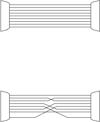
If you are interfacing a DTE device to Print Master (DCE), you must use a one-to-one or straight cable as in Figure 2 on the following page. If you are interfacing a DCE device to Print Master, you must use a crossed cable as in Figure 3 on the following page.
When using XON/XOFF protocol, it may be desirable to use cables with only Tx, Rx and SGND (signal ground) connected. On the serial ports of Print Master, input handshaking lines are enabled if nothing is connected allowing the system to operate with only Tx, Rx and SGND connected.
CAUTION: Do not attempt to use a serial cable on a parallel port.
Since an EIA-232 serial port usually carries a potential of +12 and -12 volts, plugging a serial cable from that port into a parallel port may cause damage to the parallel port.
17
PRINT MASTER - DCE |
|
|
DTE DEVICE |
||
MALE DB-25 |
|
|
|
|
MALE/FEMALE DB-25 |
1 |
PGND |
|
|
PGND |
1 |
2 |
TXD |
< |
|
TXD |
2 |
3 |
RXD |
|
> |
RXD |
3 |
4 |
RTS |
< |
|
RTS |
4 |
5 |
CTS |
|
> |
CTS |
5 |
6 |
DSR |
|
> |
DSR |
6 |
7 |
SGND |
|
|
SGND |
7 |
8 |
DCD |
|
> |
DCD |
8 |
20 |
DTR |
< |
|
DTR |
20 |
FIGURE 2
PRINT MASTER - DCE |
|
|
DCE DEVICE |
||
MALE DB-25 |
|
|
|
|
MALE DB-25 |
1 |
PGND |
|
|
PGND |
1 |
2 |
TXD |
< |
< |
TXD |
2 |
3 |
RXD |
|
|
RXD |
3 |
4 |
RTS |
< |
< |
RTS |
4 |
5 |
CTS |
|
|
CTS |
5 |
6 |
DSR |
|
|
DSR |
6 |
7 |
SGND |
|
|
SGND |
7 |
20 |
DTR |
< |
< |
DTR |
20 |
FIGURE 3
NOTE: Please refer to Appendix A for recommended cabling between Print Master and various computers and peripheral devices.
18

! "
#$
The EIA-232 serial ports of the Print Master Models 706C, 708C, or
710C may have RJ-45 modular connectors. This section will address the cabling and modular adapter information required for 700C models with RJ-45 modular connectors. BayTech has a complete line of RJ-45 adapters and cables that will make your installation quick and trouble free. Call your dealer or BayTech for order information.
The 700C models with modular connectors uses the following signals for communications:
RJ-45 PIN-OUT INFORMATION
|
PIN |
SIGNAL |
DIRECTION |
DESCRIPTION |
|
|
|
|
|
|
|
|
1 |
RTS |
Output |
Handshake out, Normally +10V |
|
|
|
|
|
|
|
|
2 |
DTR |
Output |
Handshake out, enable/disable the inputting of |
|
|
|
|
|
characters |
|
|
|
|
|
|
|
|
3 |
TX |
Output |
Transmit Data |
|
|
|
|
|
|
|
|
4 |
GND |
---- |
Signal Ground |
|
|
|
|
|
|
|
|
5 |
GND |
---- |
Signal Ground |
|
|
|
|
|
|
|
|
6 |
RX |
Input |
Receive Data |
|
|
|
|
|
|
|
|
7 |
CTS |
Input |
Handshake In, enable/disable the outputting of |
|
|
|
|
|
characters |
|
|
|
|
|
|
|
|
8 |
DSR |
Input |
Handshake In, not used. |
|
|
|
|
|
|
|
Following are drawings of a RJ-45 receptacle and plug. The pin number assignments are given.
19
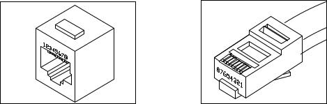
Figure 4: RJ-45 Receptacle |
Figure 5: RJ-45 Plug |
Please see Appendix A.5 for modular adapter pinout and cabling information.
This section discusses the various user-programmable configurations
(Section 6.1), printer sharing operation (Section 6.2), the LED indicators (Section 6.3), and data flow control (Section 6.4).
User-programmable configurations include the Port Logical Name, the
Number of Printers/Port Assignment, the Printer Select Code, the
Printer Select Mode, the Serial Port Configuration, the Input Inactivity
Timeout, the Form Feed Mode, and the Header Page Message. The following subsections describe these parameters in detail.
#
The Port Logical Name is simply an aid to identifying which device is connected to which port. It is used in the configuration menus and the
Header Page Message. It has no function other than identification.
Factory default is Device A for Port 1, Device B for Port 2,..., and Device J for Port 10.
20
# % #
Individual ports on Print Master may be configured as computer or printer via the Number of Printers/Port Assignment. Computers connect to computer ports. Printers and plotters connect to printer ports.
On all models, a minimum of one port must be assigned as a printer port and a minimum of one port must be assigned as a computer port.
It is suggested that the highest numbered port, the master configuration port, be assigned as a computer port to allow easy access to all features of the configuration mode. The remaining ports may be user-designated as computer ports or printer ports in any combination except for the 700A and 700C models. Print Master automatically converts data from serial-to-parallel and parallel-to- serial.
On the 700A and 700C models, ports are assigned by defining the
Number of Printers. Printer ports are assigned to the lowest numbered ports. For example, if the Number of Printers is 1, Port 1 is the printer port and the remaining ports are computer ports. If the Number of Printers is 3, Ports 1, 2, and 3 are printer ports and the remaining ports are computer ports.
On 700D, 700E and 700F models with combination serial/parallel ports, ports are defined by configuring the Port Assignment for individual ports to computer or printer. Any serial or parallel port may be assigned as a computer port or printer port.
NOTE: On Print Master models 710C, 710E and 710F, Port 10 may not be assigned as a printer port.
The factory default printer port on all Print Master models is Port 1 and all other ports are assigned as computer ports.
21
#
To select a printer in multiple printer applications, the computer sends the Printer Select Code (which consists of any ASCII character string numbering from one to eight characters) followed by the desired printer port number.
The Printer Select Code is trapped by Print Master if it is valid and not passed to the printer. This code may be sent by inserting it into a file or by using BayTech's memory resident port select program which will automatically send it by striking hot keys or using a mouse.
Section 6.2 discusses how to use the Printer Select Code to select printer ports.
Factory default is $PRINTER.
#
In multiple printer applications, you can choose between two methods of selecting printers. Mode 1 allows the computer to select the printer at the beginning of printing only. The unit is transparent after 16 characters or more. Mode 2 is a general-purpose mode which allows the computer to select a printer anytime while printing by sending the new Printer Select Code.
NOTE: In Printer Select Mode 1 (beginning of printing only) the Model 706A and 708A will recognize the printer select code only if the very first characters of the print job contain the printer select code.
Factory default is Mode 2: selection anytime while sending.
22
 Loading...