


Installation,
Operation and
Maintenance
Instructions
Models 3885, 3886, 3887
Owner’s Information
Model Number:
Serial Number:
Dealer:
Dealer’s Phone No.
Date of Purchase: |
|
|
Installation: |
|
||||
Current Readings at Startup: |
|
|
|
|
||||
Single Phase: |
|
|
|
|
|
|
|
|
Three Phase – 1st Phase: |
|
|
|
|
||||
2nd Phase: |
|
|
3rd Phase: |
|
|
|||
Table of Contents |
|
SUBJECT |
PAGE |
Safety Instructions ................................................................. |
2 |
Description and Specifications ............................................. |
2 |
Lifting of Pump ..................................................................... |
2 |
Sliderail System .................................................................... |
2 |
Piping ..................................................................................... |
2 |
Access Doors ......................................................................... |
3 |
Liquid Level Controls ........................................................... |
3 |
Pump Motor Control Panels .................................................. |
3 |
Wiring and Grounding .......................................................... |
3 |
Operation ............................................................................... |
4 |
Maintenance .......................................................................... |
4 |
Disassembly/Assembly ......................................................... |
5 |
Mechanical Seal Replacement .......................................... |
5 |
Power Cable Replacement ................................................ |
5 |
Start Capacitor Replacement ............................................. |
6 |
Motor Replacement ........................................................... |
6 |
Engineering Data ................................................................... |
7 |
Sectional Assembly .............................................................. |
8 |
Repair Parts and Materials of Construction .................... |
9, 10 |
Typical 2" Slide Rail Installation ........................................ |
11 |
Typical Plumbing and Installation ...................................... |
11 |
Trouble Shooting ................................................................. |
12 |
Goulds Pumps Limited Warranty ....................................... |
12 |
IM059R02
SAFETY INSTRUCTIONS
TO AVOID SERIOUS OR FATAL PERSONAL INJURY OR MAJOR PROPERTY DAMAGE, READ AND FOLLOW ALL SAFETY INSTRUCTIONS IN MANUAL AND ON PUMP.
THIS MANUAL IS INTENDED TO ASSIST IN THE INSTALLATION AND OPERATION OF THIS UNIT AND MUST BE KEPT WITH THE PUMP.

 DANGER

 WARNING

 CAUTION
This is a SAFETY ALERT SYMBOL. When you see this symbol on the pump or in the manual, look for one of the following signal words and be alert to the potential for personal injury or property damage.
Warns of hazards that WILL cause serious personal injury, death or major property damage.
Warns of hazards that CAN cause serious personal injury, death or major property damage.
Warns of hazards that CAN cause personal injury or property damage.
NOTICE:INDICATES SPECIAL INSTRUCTIONS WHICH ARE VERY IMPORTANT AND MUST BE FOLLOWED.
THOROUGHLY REVIEW ALL INSTRUCTIONS AND WARNINGS PRIOR TO PERFORMING ANY WORK ON THIS PUMP.
MAINTAIN ALL SAFETY DECALS.

 WARNING
Hazardous fluids can cause fire, burns or death.
UNIT NOT DESIGNED FOR USE WITH HAZARDOUS LIQUIDS OR FLAMMABLE GASES. THESE FLUIDS MAY BE PRESENT IN CONTAINMENT AREAS.
NOTICE: INSPECT UNIT FOR DAMAGE AND REPORT ALL DAMAGE TO THE CARRIER OR DEALER IMMEDIATELY.
DESCRIPTION AND SPECIFICATIONS
The Model 3885 is a 2" NPT discharge, 3⁄4" (19 mm) solids handling, submersible effluent pump. The Model 3886 is a 2" (50 mm) solids handling, submersible sewage pump. The Model 3887 is a 2" flanged (standard) 3" flange (optional) discharge, 2" (50 mm) solids handling, submersible sewage pump.
Lifting of Pump
WARNING |
DO NOT LIFT, CARRY OR HANG |
|
PUMP BY THE ELECTRICAL |
||
|
||
|
CABLES. DAMAGE TO THE |
|
|
ELECTRICAL CABLES CAN CAUSE |
|
|
SHOCK, BURNS OR DEATH. |
Hazardous voltage can shock, burn or cause death.
•Lift the pump with an adequately sized chain or cable attached to the lifting handle (458). DO NOT damage electrical cables while raising and lowering unit.
Sliderail System
•The OPTIONAL Goulds Model A10-20 sliderail system is recommended for proper installation.
NOTICE: FOLLOW THE INSTALLATION AND OPERATION INSTRUCTIONS PROVIDED WITH THE SLIDERAIL SYSTEM.
•Installation of the sliderail system should locate the pump opposite the influent opening, preventing stagnate areas where solids can settle.
•The pit floor MUST be flat under the sliderail base and have sufficient loading capacity to support the entire weight of the assembly, including the sliderail base, sliderail guide, pump and all assorted piping.
Piping
•Discharge piping should be no smaller than 2" (51 mm) diameter and kept as short as possible, avoiding unnecessary fittings to minimize friction losses.
•Install an adequately sized check valve (suitable for handling 3⁄4" (19 mm) solids for effluent applications and 2" (50 mm) solids for sewage applications) in the discharge pipe to prevent backflow. Follow the check valve manufacturer’s installation instructions.
•Install an adequately sized gate valve ABOVE the check valve for pump, plumbing and check valve maintenance.
•To deter air locking, drill a3⁄16" (4.8 mm) hole, 2" (50.8 mm) beyond the pump discharge connection.
•All piping must be adequately supported, so as not to impart any piping strain or loads on the pump.
2
Access Doors
•Access doors can be single or double leaf design. Doors should include a lifting handle and a lock provision for tamper resistant operation. Standard and heavy duty steel or aluminum doors are available.
•The pit access door must be of sufficient size to allow for inspection, maintenance and crane or hoist service.
Liquid Level Controls
•Single float operation can be used on1⁄3 and 1⁄2 HP models. Mounting of the float switch must be checked by the installer to insure proper turn on and turn off. The pump may be plugged directly into the piggy back style plug located on the cord of the float switch.
•The recommended float operation sequence used with a control panel requires a three or four float system. In the three float system, the floats are designated SW-1 for the bottom float, SW-2 for the middle float and SW-3 for the top float. In a four float system the fourth float is designated SW-4.
•Simplex Control – The rising liquid level raises float SW-2, turning on the pump. When the liquid level falls sufficiently, SW-1 will turn the pump off. If the influent is excessive, or if the pump fails to operate correctly, SW-3 will activate an alarm, which will remain on until manually reset.
•Duplex Control – The duplex control will alternate the two pumps, causing the lead pump to change at each system cycle. When equipped with three floats, the system will cycle the same as the simplex control, described above, except that the SW-1 will cause the lead pump to alternate.
•If the influent is excessive, or if the lead pump fails to operate correctly, the rising level will activate SW-3, turning on the lag pump and the alarm. As before the alarm must be manually reset.
•Four Float Control – The four float system operates the same as the duplex control system, except that float SW-3 will not turn on the alarm. In this system SW-4 turns on the alarm, which again must be manually reset.
•Several different float controls are available from the Goulds Catalog.
NOTICE: POSITION THE FLOATS SO THAT THEY DO NOT SNAG OR TANGLE ON THE PUMP, DISCHARGE PIPING, OR OTHER EQUIPMENT.
•The lower most float turns the unit off and should be set as shown in the “TYPICAL PLUMBING and INSTALLATION” drawing provided in this manual.
•Increasing the distance between the SW-1 and SW-2 floats lengthens the running time. One (1) minute is the minimum recommended pump cycle time.
NOTICE: DURING PUMP OPERATION, INSURE THAT THE LIQUID LEVEL DOES NOT DROP BELOW THE PUMP MOTOR FOR EXTENDED PERIODS. THIS CAN CAUSE THE PUMP MOTOR TO OVERHEAT, CAUSING MOTOR DAMAGE AND VOIDING THE WARRANTY.
Pump Motor Control Panels
•Control panels shall be in accordance with local and National Electrical Code requirements.
•Single phase installations shall be equipped with a Goulds’
“SES” or “A” Series panel, or AS A MINIMUM, a control panel with a properly sized magnetic contactor and a disconnect switch.
• Three phase installations shall be equipped with a Goulds’ “SES” or “A” Series panel, or AS A MINIMUM with a 3 pole circuit breaker, an across the line magnetic starter NEMA rated for the appropriate horsepower, ambient compensated Quick Trip Class 10 overload relays.
Wiring and Grounding
•Use only stranded copper wire to motor and ground. The ground wire must be at least as large as the wires to the motor. Wires should be color coded for ease of maintenance.

 WARNING
Hazardous voltage can shock, burn or cause death.
Install, ground and wire according to local and National Electrical Code requirements.
Install an all leg disconnect switch near the pump.
Disconnect and lockout electrical power before installing or servicing pump.
Electrical supply MUST match pump’s nameplate specifications. Incorrect voltage can cause fire, damage motor and voids warranty.
Single phase motors are equipped with automatic thermal protectors which open the motor’s electrical circuit when an overload exists. This can cause the pump to start unexpectedly and without warning.
Some models are equipped with a 3-prong grounded plug and MUST be used in a grounded 3-wire receptacle. DO NOT modify the plug or remove the ground prong.
•Where cables must be spliced or connected to the motor leads, splices MUST be water tight. Commercially available potting or heat shrink kits may be used, if allowed by local or federal regulations.
3

NOTICE: FOLLOW THE SPLICE KIT MANUFACTURER’S INSTRUCTIONS.
•Where wire splices are used, follow one of these procedures:
•Butt join the wires using properly sized and correctly crimped Sta-Kon™, or equivalent, connectors. Insulate and water proof each joint using heat shrink tubing equipped with a self contained sealer. Apply heat evenly from a torch until adequately sealed.
OR
•Use plastic insulators and a neoprene gasket sleeve set with properly sized and correctly crimped Sta-Kon™ connectors. Place a cap and gasket on each wire end, center insulator body over splice, insert the sleeve into the body as far as possible, hand tighten caps.
•In the case of multiple conductors, stagger the joints.
WARNING |
FAILURE TO PERMANENTLY |
|
GROUND THE PUMP, MOTOR AND |
||
Hazardous |
||
CONTROLS BEFORE CONNECTING |
||
voltage |
TO ELECTRICAL POWER CAN |
|
|
CAUSE SHOCK, BURNS OR DEATH. |
Operation
•If the unit has been stored for an extended period, check the oil level in the motor and seal chamber, to insure that they are full, using the following procedures:
•Motor Cover – With the pump in the upright position, remove the oil fill plug (358E), being careful that nothing enters the motor. The oil level should be above the top of the motor. With the correct oil fill as required. DO NOT over fill.
•Cable Gland Assemblies – Re-torque both the power and sensor cable glands to values given in step 10 of
“POWER CABLE REPLACEMENT ”.
•Before lowering the pump(s) into the containment area, three phase units should be jogged to insure correct rotation. See the motor rotation arrow on the motor cover (341). Check both pumps in a duplex operation.
NOTICE:MOTOR STARTUP TORQUE, “KICKBACK”, WILL CAUSE THE MOTOR TO TWIST IN THE DIRECTION OPPOSITE ROTATION. INSURE THAT THE PUMP ASSEMBLY IS ADEQUATELY RESTRAINED.
! DANGER |
Hazardous Machinery |
DO NOT PLACE HANDS IN PUMP SUCTION WHILE CHECKING MOTOR ROTATION. TO DO SO WILL CAUSE SEVERE PERSONAL INJURY.
NOTICE: DO NOT SWITCH PRIMARY POWER LEADS COMING INTO A THREE PHASE DUPLEX CONTROL PANEL, THIS WILL REVERSE ROTATION OF BOTH PUMPS.
•If the three phase motor(s) rotation is backwards, reverse any two pump power cable leads at the pump control panel.
WARNING |
MOTOR OVERHEAT/OVER |
|
CURRENT SENSING DEVICES |
||
Hazardous |
||
AUTOMATICALLY RESTART THE |
||
machinery |
||
MOTOR UNEXPECTEDLY AND |
||
|
||
|
WITHOUT WARNING. THIS CAN |
CAUSE SEVERE PERSONAL
INJURY.
•After installing the pump into the containment area, with adequate submergence, open the discharge valve fully. Start the unit using manual controls. If flow is appreciably less than rated performance, pump may be air bound. To expel trapped air, jog the unit several times, using the manual controls.
•Have a qualified electrician take current measurements on the single or all three phases. Record these readings in the space provided in the “OWNER’S INFORMATION ” section of this manual for future reference.
•The unit is now ready for normal operation. Place the controls in the automatic position.
Maintenance
WARNING |
FAILURE TO DISCONNECT AND |
|
LOCKOUT ELECTRICAL POWER |
||
Hazardous |
||
BEFORE ATTEMPTING ANY |
||
voltage |
MAINTENANCE CAN CAUSE |
|
|
SHOCK, BURNS OR DEATH. |
|
|
UNIT MUST BE FLUSHED AND |
|
WARNING |
||
DISINFECTED, INSIDE AND OUT, |
||
|
||
|
PRIOR TO SERVICING. |
Biohazard can cause serious personal injury.
Periodic Maintenance
NOTICE: ROUTINE PERIODIC INSPECTIONS ARE REQUIRED AND SHOULD FOLLOW THE FREQUENCY AND MAINTENANCE SCHEDULE PROVIDED.
FREQUENCY |
REQUIRED MAINTENANCE |
MONTHLY |
• Duplex Units – Check for even |
|
operating times. Uneven operation |
|
times indicate a defective unit, float |
|
switch or control. |
|
• Unimpeded float operation. |
|
|
4

Disassembly/Assembly
WARNING |
FAILURE TO DISCONNECT AND |
|
LOCKOUT ELECTRICAL POWER |
||
Hazardous |
||
BEFORE ATTEMPTING ANY |
||
voltage |
MAINTENANCE CAN CAUSE |
|
|
SHOCK, BURNS OR DEATH. |
NOTICE: FOLLOW ALL SAFETY AND LIFTING INSTRUCTIONS PROVIDED IN THIS MANUAL.
•Following the slide rail instructions, remove the pumping unit from the sewage containment area.
WARNING |
UNIT MUST BE FLUSHED AND |
|
DISINFECTED, INSIDE AND OUT, |
||
|
||
|
PRIOR TO SERVICING. |
Biohazard can cause serious personal injury.
MECHANICAL SEAL REPLACEMENT
1. Follow ALL instructions provided in the “DISASSEMBLY ” section of this manual.
2. To gain access to the pump impeller and mechanical seal remove the four casing hex cap screws (372D). Remove casing (100) and casing gasket (351); discard the gasket.
 CAUTION
Hazardous pressure can cause personal injury or property damage.
FAILURE TO REMOVE DRAIN PLUG CAREFULLY CAN CAUSE HOT OIL TO ERUPT FROM OIL RESERVOIR CAUSING PERSONAL INJURY OR PROPERTY DAMAGE
3. Removal of the mechanical seal assembly (387) requires draining the special insulating oil from the motor cover. This is accomplished by removing the drain plug and draining the oil into an adequately sized clean receptacle. See “ENGINEERING DATA ” section for required volume.
4. To remove the impeller (101), it may be necessary to heat the impeller and impeller locknut (304), three phase motors only, with a torch. Use no more heat that is necessary, as excess heat will damage the mechanical seal. Secure the impeller from rotation, and remove
the impeller lock nut, by turning the lock nut COUNTERCLOCKWISE. Remove the impeller from the motor shaft by holding the motor shaft with a screw driver and turning the impeller COUNTER-
CLOCKWISE.
5. Remove and discard the mechanical seal and stationary seat assembly. DO NOT damage the motor shaft or the stationary seat bore.
6. Inspect and wipe clean the stationary seat bore.
7. To install the new stationary seat into the seal housing, lubricate the stationary seat bore and motor shaft with clean motor insulating oil. Using Goulds mechanical seal installation tool (A02A013), slide the stationary seat fully and squarely into the seal housing.
8. With a clean, lint free cloth, wipe the stationary face clean of all lubricating oil or debris. DO NOT scratch or otherwise damage the seal face.
9. Lubricate the inside of the rotary elastomer with clean motor insulating oil. Using the Goulds installation tool, slide the seal rotary assembly onto the motor shaft and seat fully against the stationary seat. Remove the seal installation tool.
10. Install the impeller onto the motor shaft by turning the impeller on CLOCKWISE, tighten securely. Treat the impeller with Loctite™ #271 and securely install. When provided, securely install the impeller locknut.
11. Fill the motor cover with motor special insulating oil to within 1⁄2" (13 mm) of the seal chamber housing. Tape drain plug with Teflon™ tape and install plug securely.
12. Reassemble casing and new casing gasket to pump assembly by installing the four casing hex cap screws, torquing in sequence to 35 lbs ft (47 Ν m).
NOTICE: FOLLOW THE INSTRUCTIONS PROVIDED IN THE “WIRING AND GROUNDING ” AND
“OPERATION ” SECTIONS OF THE MANUAL AFTER UNIT DISASSEMBLY, REASSEMBLY.
POWER CABLE REPLACEMENT
1. To gain access to the motor cover screws follow steps 1 through 6 in the “MECHANICAL SEAL REPLACEMENT” section of this manual.
2. Remove the power cable strain relief (484B) assembly from the motor cover and slide up the cable.
3. Remove the four bearing housing socket head screws (371C). Carefully slide the motor cover from the motor assembly. DO NOT damage the power cable.
4. Disconnect the power cable wires from the motor assembly (338).
5. Remove cable from motor cover, inspect and replace as required, following the procedures provided.
NOTICE: DISCARD STRAIN RELIEF ASSEMBLY.
THEY CAN NOT BE REUSED.
6. Install new motor cable strain relief assembly onto cable, sliding the hex gland on first, then the washer and finally the packing. Insert the cables into the motor cover hole.
Pull an appropriate amount of cable through the motor cover to allow for connecting the cable leads. DO NOT tighten the strain relief gland.
5
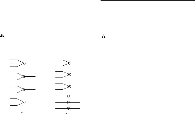
7. Connect the power cable leads to the motor assembly as follows:
•Single Phase Motors – Connect theBLACK wire to motor terminal L1. Connect the WHITE wire to motor terminal L2. Connect the GREEN wire to the motor ground.
•Three Phase Motors – See Figure 1.
WARNING |
FAILURE TO CONNECT POWER |
|
AND SENSOR WIRES TO |
||
Hazardous |
||
DESIGNATED WIRES CAN CAUSE |
||
voltage |
SHOCK, BURNS OR DEATH. |
|
|
208-230 V 3/60 |
|
|
|
460 V 3/60 |
|
|
|||||
|
4 |
|
|
|
|
|
|
|
4 |
|
|
|
|
|
5 |
|
|
|
|
|
|
|
7 |
|
|
|
|
|
6 |
|
|
|
|
|
|
|
|
|
|
|
|
|
1 |
|
|
|
|
CABLEPOWERLEADS |
|
|
5 |
|
|
|
CABLEPOWERLEADS |
MOTORLEADS |
|
|
|
L1 |
|
MOTORLEADS |
|
|
|
|
|||
3 |
|
|
|
|
8 |
|
|
|
|||||
|
7 |
|
|
|
|
|
|
|
|
|
|
|
|
|
2 |
|
|
|
|
|
|
|
6 |
|
|
|
|
|
8 |
|
|
|
L2 |
|
|
|
9 |
|
|
|
|
|
|
|
|
|
|
|
|
1 |
|
|
L1 |
|
|
|
|
|
|
|
|
|
|
|
|
|
|
||
|
9 |
|
|
|
L3 |
|
|
|
2 |
|
|
L2 |
|
|
|
|
|
|
|
|
|
3 |
|
|
L3 |
|
|
|
|
|
|
|
G |
|
|
|
|
|
|
||
|
|
|
|
|
|
|
|
|
|
|
G |
|
|
|
|
|
|
|
|
|
|
|
|
|
|
|
|
|
|
|
|
|
|
|
|
|
|
|
|
||
|
|
THREE PHASE MOTOR WIRING DIAGRAM |
|
|
|||||||||
|
|
|
|
|
Figure 1 |
|
|
||||||
8. Wire tie the power cable to the motor assembly.
9. Slide the motor cover onto the motor assembly, while carefully pulling the power cable out through the motor cover hole. DO NOT damage cables. Install the four seal housing socket head screws, torquing to 90 lbs in (10 Ν m).
10. Install the power cable strain relief assembly torquing the nylon bushing to 75 lbs in (8.5 Ν m) and the steel bushing to 100 lbs in (11.3 Ν m).
11. Continue the assembly following steps 7 through 12 of the “MECHANICAL SEAL REPLACEMENT ” section of this manual.
12. If the motor cover was replaced, it is necessary to transfer the Goulds nameplate. Using two stainless steel No. 2 round head metallic drive screws, install the Goulds nameplate.
NOTICE: FOLLOW THE INSTRUCTIONS PROVIDED IN THE “WIRING AND GROUNDING ” AND
“OPERATION ” SECTIONS OF THE MANUAL AFTER UNIT DISASSEMBLY, REASSEMBLY.
START CAPACITOR REPLACEMENT
1. On single phase motors only, to gain access to the motor start capacitor (376), follow steps 1 through 5 in the
“POWER CABLE REPLACEMENT ” section of this manual.
NOTICE: DISCARD STRAIN RELIEF ASSEMBLY. IT CAN NOT BE REUSED.
|
FAILURE TO DRAIN CAPACITOR |
|
WARNING |
||
OF STORED ELECTRICAL |
||
Hazardous |
||
CHARGE BEFORE SERVICE CAN |
||
voltage |
CAUSE A SEVERE SHOCK. |
2. Remove the capacitor retaining screw and retaining bracket from the motor assembly. Remove the two wires from the capacitor. Discard the capacitor.
3. Connect the two motor wires to the new capacitor and reassemble with the retaining bracket and retaining screw, tightening securely.
4. Reassemble unit following steps 6 through 12 in the
“POWER CABLE REPLACEMENT ” section of this manual.
NOTICE: FOLLOW THE INSTRUCTIONS PROVIDED IN THE “WIRING AND GROUNDING ” AND
“OPERATION ” SECTIONS OF THE MANUAL AFTER UNIT DISASSEMBLY, REASSEMBLY.
MOTOR REPLACEMENT
1. To gain access to the motor assembly, follow steps 1 through 5 in the“POWE R CABLE REPLACEMENT ” section of this manual.
NOTICE: DISCARD STRAIN RELIEF ASSEMBLY. IT CAN NOT BE REUSED.
2. Remove the four motor thru bolts and carefully pull motor assembly from bearing housing. Further motor service MUST be provided by a qualified motor repair facility.
3. Insert the motor assembly into the bearing housing, visually aligning the motor thru bolts through the lower motor vent openings.
4. Install the four motor thru bolts, torquing to 35 lbs in (4 Ν m).
5. To complete the assembly follow steps 6 through 12 in the “POWER CABLE REPLACEMENT ” section of this manual.
NOTICE: FOLLOW THE INSTRUCTIONS PROVIDED IN THE “WIRING AND GROUNDING ” AND
“OPERATION ” SECTIONS OF THE MANUAL AFTER UNIT DISASSEMBLY, REASSEMBLY
6

Engineering Data
Maximum Diameter Solids |
|
|
3885 |
3⁄4 in |
19 mm |
3886 and 3887 |
2 in |
50 mm |
Minimum Casing Thickness |
5⁄16 in |
8 mm |
Casing Corrosion Allowance |
1⁄8 in |
3 mm |
Minimum Working Pressure |
55 psi |
380 kPa |
ELECTRICAL DATA 3885
Minimum Pump Submergence – Below Top of Motor Dome |
6 in |
152 mm |
Minimum Number of Evenly Distributed Starts per Hour |
|
6 |
Maximum Operating Temperature |
40° C |
104° F |
Continuous Operation |
||
Intermittent Operation |
60° C |
140° F |
Motor Cover Oil Capacity |
4.5 qts. |
4.3 L |
HP |
RPM |
Voltage |
Phase |
Amps |
KVA |
Winding Resistance |
Power |
Fuse/Circuit |
|
/Hz |
Code |
Line to Line (Ohms) |
Cable AWG |
Breaker Amps |
|||||
|
|
|
|
||||||
1⁄3 |
1725 |
115 |
1/60 |
9.4 |
M |
1.92 |
16/3 |
15 |
|
1⁄3 |
1725 |
230 |
1/60 |
4.7 |
N |
7.58 |
16/3 |
10 |
|
1⁄2 |
3450 |
115 |
1/60 |
14.5 |
M |
1.00 |
16/3 |
20 |
|
1⁄2 |
3450 |
230 |
1/60 |
7.3 |
M |
4.03 |
16/3 |
10 |
|
1⁄2 |
3450 |
200 |
3/60 |
3.9 |
R |
3.8 |
14/4 |
10 |
|
1⁄2 |
3450 |
230/460 |
3/60 |
3.4/1.7 |
R |
5.81/23.24 |
14/4 |
10/10 |
|
3⁄4 |
3450 |
230 |
1/60 |
10.0 |
J |
2.99 |
14/3 |
15 |
|
3⁄4 |
3450 |
200 |
3/60 |
6.2 |
L |
5.7 |
14/4 |
10 |
|
3⁄4 |
3450 |
230/460 |
3/60 |
5.4/2.7 |
L |
4.04/16.15 |
14/4 |
10/10 |
|
1 |
3450 |
230 |
1/60 |
12.5 |
J |
2.09 |
14/3 |
20 |
|
1 |
3450 |
200 |
3/60 |
8.1 |
M |
2.6 |
14/4 |
10 |
|
1 |
3450 |
230/460 |
3/60 |
7.0/3.5 |
L |
4.04/16.15 |
14/4 |
10/10 |
|
11⁄2 |
3450 |
230 |
1/60 |
15.0 |
H |
1.16 |
14/3 |
20 |
|
11⁄2 |
3450 |
200 |
3/60 |
10.6 |
K |
1.9 |
14/4 |
15 |
|
11⁄2 |
3450 |
230/460 |
3/60 |
9.2/4.6 |
K |
2.87/11.46 |
14/4 |
15/10 |
|
2 |
3450 |
230 |
1/60 |
18.0 |
F |
M-1.1/S-2.2 |
14/3 |
20 |
|
2 |
3450 |
200-230/460 |
3/60 |
12.0-11.6/5.8 |
K |
1.66/6.62 |
14/4 |
15/10 |
|
ELECTRICAL DATA 3886 AND 3887BF |
|
|
|
|
|
|
|||
1⁄3 |
1725 |
115 |
1/60 |
9.8 |
M |
1.92 |
16/3 |
15 |
|
1⁄3 |
1725 |
230 |
1/60 |
4.9 |
N |
7.58 |
16/3 |
10 |
|
1⁄2 |
1725 |
115 |
1/60 |
14.5 |
N |
1.6 |
16/3 |
20 |
|
1⁄2 |
1725 |
230 |
1/60 |
7.3 |
K |
6.4 |
16/3 |
10 |
|
1⁄2 |
1725 |
200 |
3/60 |
3.8 |
K |
6.55 |
14/4 |
10 |
|
1⁄2 |
1725 |
230/460 |
3/60 |
3.3/1.7 |
K |
9.9/39.4 |
14/4 |
10/10 |
|
3⁄4 |
1725 |
230 |
1/60 |
9.4 |
J |
5.9 |
14/3 |
15 |
|
3⁄4 |
1725 |
200 |
3/60 |
4.1 |
H |
4.3 |
14/4 |
10 |
|
3⁄4 |
1725 |
230/460 |
3/60 |
3.6/1.8 |
J |
5.6/22.4 |
14/4 |
10/10 |
|
1 |
1725 |
230 |
1/60 |
12.3 |
H |
2.6 |
14/3 |
20 |
|
1 |
1725 |
200 |
3/60 |
6.0 |
H |
4.3 |
14/4 |
10 |
|
1 |
1725 |
230/460 |
3/60 |
5.8/2.9 |
J |
5.6/22.4 |
14/4 |
10/10 |
|
ELECTRICAL DATA 3887BHF |
|
|
|
|
|
|
|
||
1⁄3 |
1725 |
115 |
1/60 |
12.4 |
M |
1.00 |
16/3 |
15 |
|
1⁄3 |
1725 |
230 |
1/60 |
6.2 |
M |
4.03 |
16/3 |
10 |
|
1⁄2 |
3450 |
115 |
1/60 |
14.5 |
M |
1.00 |
16/3 |
20 |
|
1⁄2 |
3450 |
230 |
1/60 |
7.6 |
M |
4.03 |
16/3 |
10 |
|
1⁄2 |
3450 |
200 |
3/60 |
4.1 |
R |
3.8 |
14/4 |
10 |
|
1⁄2 |
3450 |
230/460 |
3/60 |
3.6/1.8 |
R |
5.81/23.24 |
14/4 |
10/10 |
|
3⁄4 |
3450 |
230 |
1/60 |
9.4 |
J |
2.99 |
14/3 |
15 |
|
3⁄4 |
3450 |
200 |
3/60 |
6.2 |
L |
5.7 |
14/4 |
10 |
|
3⁄4 |
3450 |
230/460 |
3/60 |
5.4/2.7 |
L |
4.04/16.15 |
14/4 |
10/10 |
|
1 |
3450 |
230 |
1/60 |
14.5 |
J |
2.1 |
14/3 |
20 |
|
1 |
3450 |
200 |
3/60 |
8.6 |
M |
2.6 |
14/4 |
10 |
|
1 |
3450 |
230/460 |
3/60 |
7.5/3.8 |
L |
4.0/16.2 |
14/4 |
10/10 |
|
11⁄2 |
3450 |
230 |
1/60 |
18.0 |
F |
M-1.1/S-2.2 |
14/3 |
20 |
|
11⁄2 |
3450 |
200-230/460 |
3/60 |
10.0-9.6/4.8 |
K |
1.66/6.62 |
14/4 |
15/10 |
|
2 |
3450 |
230 |
1/60 |
18.0 |
F |
M-1.1/S-2.2 |
14/3 |
20 |
|
2 |
3450 |
200-230/460 |
3/60 |
12.0-11.6/5.8 |
K |
1.66/6.62 |
14/4 |
15/10 |
|
7

Repair Parts Diagram for Models 3885, 3886 and 3887
458
376
338
372D
340
101
351
100
456 GROUP
484B
457
436
341
112A
|
412M |
|
Note: Models 3885 and 3886 are not flanged |
|
and therefore do not require some of the |
|
diagramed parts. |
|
371H |
387 |
371C |
|
195C
351A
304 |
357 |
|
8

Model 3885 Repair Parts Table
Item |
|
|
|
|
|
|
|
|
|
Qty. |
|
|
|
|
|
Repair Parts Order Number |
|
|
|
|
|
Max. Wt. |
|||||||||
Part Name |
|
|
|
Material |
|
1725 RPM |
|
|
|
|
|
3450 RPM |
|
|
|
|
|
|
|
||||||||||||
No. |
|
|
|
Reqd. |
|
|
|
|
|
|
|
|
|
|
|
|
(lbs.) |
||||||||||||||
|
|
|
|
1⁄3 HP |
1⁄2 HP |
3⁄4 HP |
|
1 HP |
|
|
11⁄2 HP |
|
2 HP |
|
|||||||||||||||||
|
|
|
|
|
|
|
|
|
|
|
|
|
|
|
|
|
|
|
|
||||||||||||
100 |
Casing – 1⁄3 HP “L” model only |
Cast Iron |
1 |
|
|
1K171 |
|
|
|
|
|
N/A |
|
|
|
|
|
|
|
|
|
13.0 |
|||||||||
Casing – all others |
|
|
|
|
|
|
|
|
|
|
1K170 |
|
|
|
|
|
|
|
|
|
|||||||||||
|
|
|
|
|
|
|
|
|
|
|
|
|
|
|
|
|
|
|
|
|
|
|
|
||||||||
|
Impeller |
|
|
|
Cast Iron |
|
|
|
|
2K158 |
2K220 |
2K219 |
|
2K218 |
|
|
2K217 |
|
2K840 |
|
2.0 |
||||||||||
101 |
Impeller |
|
|
|
Bronze |
|
|
|
2K271 |
2K272 |
2K273 |
|
2K274 |
|
|
2K275 |
|
2K841 |
|
2.5 |
|||||||||||
Impeller – high head |
|
|
|
Cast Iron |
1 |
|
|
|
N/A |
2K225 HH |
N/A |
|
N/A |
|
2K221HH |
|
N/A |
|
3.5 |
||||||||||||
|
|
|
|
|
|
|
|
|
|
|
|||||||||||||||||||||
|
Impeller – high head |
|
|
|
Bronze |
|
|
|
|
N/A |
2K276 HH |
N/A |
|
N/A |
|
2K277 HH |
|
N/A |
|
4.0 |
|||||||||||
112A |
Lower Ball Bearing |
|
|
|
Steel |
1 |
|
|
|
|
|
|
|
4K132 |
|
|
|
|
|
|
|
|
4K384 |
|
– |
||||||
112B |
Upper Ball Bearing |
|
|
|
Steel |
1 |
|
|
|
|
|
|
|
4K132 |
|
|
|
|
|
|
|
|
|
– |
|||||||
218 |
Insulating Oil (gallon) |
|
Turbine Oil – Sunvis |
|
|
|
|
|
|
|
|
4K432 (5 gallons) |
|
|
|
|
|
|
|
|
|
7.5 lbs./ |
|||||||||
Gallons required |
|
|
|
932, Convis 150 |
|
|
|
|
|
|
|
|
1.2 gallons |
|
|
|
|
|
|
|
|
|
gal. |
||||||||
|
|
|
|
|
|
|
|
|
|
|
|
|
|
|
|
|
|
|
|
|
|||||||||||
304 |
Impeller Locknut (3 PH only) |
|
AISI 300 series SS |
1 |
|
|
|
|
|
|
|
13K6 |
|
|
|
|
|
|
|
|
|
– |
|||||||||
|
|
|
1 Phase, 115V |
|
|
|
|
|
|
118-121R |
118-1222R |
N/A |
|
N/A |
|
|
|
N/A |
|
N/A |
|
13.0 |
|||||||||
338 |
Motor |
|
1 Phase, 230V |
|
Stainless Steel |
|
|
|
118-122R |
118-1223R |
118-1232R |
118-1233R |
118-1334R |
|
120-845R |
||||||||||||||||
|
|
1 |
|
|
|
to |
|||||||||||||||||||||||||
|
3 Phase, 230/460 V |
Short Ext. |
|
|
|
N/A |
118-1321R |
118-1322R |
118-1323R |
118-1324R |
120-8425R |
||||||||||||||||||||
|
|
|
|
|
|
|
24.0 |
||||||||||||||||||||||||
|
|
|
3 Phase, 200 V |
|
|
|
|
|
|
|
N/A |
118-1333R |
118-1334R |
118-1335R |
118-1336R |
120-8425R |
|
||||||||||||||
|
|
|
|
|
|
|
|
|
|
|
|
|
|
|
|
|
|
|
|
|
|
|
|
|
|
|
|
|
|
|
|
340 |
Bearing Housing |
|
|
|
Cast Iron |
1 |
|
|
|
|
|
|
|
1K167 |
|
|
|
|
|
|
|
|
1K332 |
|
10.0 |
||||||
341 |
Motor Cover |
1 PH |
|
Cast Iron |
1 |
|
|
1K207 |
1K207 |
1K208 |
|
1K208 |
|
|
1K208 |
|
1K208 |
|
23.0 |
||||||||||||
3 PH |
|
|
|
|
|
|
|
|
|
|
1K208 |
|
|
|
|
|
|
|
|
|
|||||||||||
|
|
|
|
|
|
|
|
|
|
|
|
|
|
|
|
|
|
|
|
|
|
|
|
|
|
|
|||||
351 |
Casing Gasket |
|
|
|
Composite |
1 |
|
|
|
|
|
|
|
5K170 |
|
|
|
|
|
|
|
|
|
– |
|||||||
358E |
Plug – motor cover 3⁄8" NPT |
|
Steel |
1 |
|
|
|
|
|
|
|
|
6K3 |
|
|
|
|
|
|
|
|
|
– |
||||||||
371C |
Skt. Hd. Screw – brg. housing to motor cover |
AISI 300 series SS |
2 |
|
|
|
|
|
|
|
13K210 |
|
|
|
|
|
|
|
|
|
– |
||||||||||
372D |
Hex Screw – seal housing to casing |
AISI 300 series SS |
4 |
|
|
|
|
|
|
|
13K186 |
|
|
|
|
|
|
|
|
|
– |
||||||||||
|
|
|
|
|
|
|
|
|
|
|
|
|
|
|
|
|
|
|
|
|
|
|
|
|
|
|
|
|
|
||
376 |
Capacitor (1 PH only) |
|
Start |
Varies |
1 |
|
|
1K197 |
9K197 |
9K197 |
|
9K197 |
|
|
9K197 |
275470130 |
– |
||||||||||||||
|
Run |
|
|
|
N/A |
N/A |
|
N/A |
|
N/A |
|
|
|
N/A |
279342110 |
||||||||||||||||
|
|
|
|
|
|
|
|
|
|
|
|
|
|
|
|
|
|
|
|||||||||||||
387 |
Mechanical Seal – standard |
|
Silicon Carbide |
1 |
|
|
|
|
10K63 (John Crane Type 6) |
|
|
|
10K71 |
|
– |
||||||||||||||||
|
|
|
|
|
|
|
|
|
|
|
|
|
|
|
|
|
|
|
|
|
|
|
|
|
|
|
|
|
|
|
|
Mechanical Seal – optional |
|
Tungsten Carbide |
1 |
|
|
|
|
10K30 (John Crane Type 21) |
|
|
|
10K72 |
|
– |
|||||||||||||||||
|
|
|
|
|
|
|
|
|
|
||||||||||||||||||||||
412M |
O-ring – motor cover |
|
|
|
BUNA-N, AS 568A-166 |
1 |
|
|
|
|
|
|
|
4K252 |
|
|
|
|
|
|
|
|
|
– |
|||||||
436 |
Solid State Switch |
|
|
|
|
|
|
|
|
|
|
|
|
|
|
N/A |
|
|
|
|
294811980 |
|
|||||||||
456 |
Power cable |
|
|
|
|
|
1 |
|
|
|
|
|
|
|
See chart below |
|
|
|
|
|
|
|
|
|
– |
||||||
457 |
Wire nut |
3 PH, 200/230 V |
Nylon Housing |
4 |
|
|
|
|
|
|
|
9K145 |
|
|
|
|
|
|
|
|
|
– |
|||||||||
(power cable) |
3 PH, 460 V |
6 |
|
|
|
|
|
|
|
9K145 |
|
|
|
|
|
|
|
|
|
– |
|||||||||||
|
|
|
|
|
|
|
|
|
|
|
|
|
|
|
|
|
|
|
|||||||||||||
458 |
Handle Assembly |
|
|
|
AISI 300 series SS |
1 |
|
|
|
|
|
|
|
4K243 |
|
|
|
|
|
|
|
|
|
– |
|||||||
484B |
Strain Relief Assembly |
|
1 PH |
Varies |
|
1 |
|
|
5K113 |
5K113 |
5K111 |
|
5K111 |
|
|
5K111 |
|
5K111 |
|
– |
|||||||||||
(power cable) |
|
|
3 PH |
|
1 |
|
|
|
N/A |
|
|
|
|
|
5K111 |
|
|
|
|
|
|
|
|
|
– |
||||||
|
|
|
|
|
|
|
|
|
|
|
|
|
|
|
|
|
|
|
|
|
|
||||||||||
|
Loctite #271 |
|
|
|
|
|
1 |
|
|
|
|
|
|
|
AL271121 |
|
|
|
|
|
|
|
|
|
– |
||||||
|
|
|
|
|
|
|
|
|
|
|
|
|
|
|
|
|
|
|
|
|
|
|
|
|
|
|
|
|
|
||
|
|
|
|
|
|
|
|
|
|
|
|
|
|
|
|
|
|
|
|
|
|
|
|||||||||
Model 3885 Power and Sensor Cables Description |
|
|
|
|
|
|
Type and |
|
Standard length* |
|
Optional Lengths |
|
|
|
Wt. |
||||||||||||||||
|
|
|
|
|
|
AWG Size |
|
|
20' |
|
|
30' |
|
|
50' |
|
100' |
|
|
(lbs./5 ft.) |
|||||||||||
|
|
|
|
|
|
|
|
|
|
|
|
|
|
|
|
|
|
|
|
|
|
||||||||||
Power Cables |
|
|
|
|
|
|
|
|
|
|
|
|
|
|
|
|
|
|
|
|
|
|
|
|
|
|
|
||||
1 PH: 1⁄3 and 1⁄2 HP, 115 V; standard with plug, optional with bare leads |
|
|
|
|
SJTOW – 16/3 |
|
|
9K165 |
|
|
9K214 |
|
9K215 |
|
N/A |
|
|
0.5 |
|||||||||||||
1 PH: 1⁄3 and 1⁄2 HP, 230 V; standard with plug, optional with bare leads |
|
|
|
|
SJTOW – 16/3 |
|
|
9K164 |
|
|
9K214 |
|
9K215 |
|
N/A |
|
|
0.5 |
|||||||||||||
1 PH: 3⁄4 – 11⁄2 HP, 230 V with bare leads |
|
|
|
|
|
|
STOW – 14/3 |
|
|
9K163 |
|
|
9K216 |
|
9K161 |
|
9K217 |
|
|
0.9 |
|||||||||||
1 PH: 11⁄2 – 2 HP, 230 V with bare leads |
|
|
|
|
|
|
STOW – 14/3 |
|
|
9K266 |
|
|
9K267 |
|
9K268 |
|
9K269 |
|
|
0.9 |
|||||||||||
3 PH: 1⁄2 – 2 HP, 208–230/460 V with bare leads |
|
|
|
|
|
|
STOW – 14/4 |
|
|
9K153 |
|
|
9K218 |
|
9K154 |
|
9K219 |
|
|
1.1 |
|||||||||||
9

Model 3886 and 3887 Repair Parts Table
Note: The 1K168 is the casing for the 3886 1⁄2 HP. The 1K178 is the casing for the 3887 1⁄3 – 1 HP.
Item |
|
|
|
|
|
|
|
|
|
|
|
Repair Parts Order Number |
|
|
|
|
|
Max. Wt. |
|||||||
Part Name |
|
|
Material |
Qty. |
|
|
1725 RPM |
|
|
|
|
|
|
3450 RPM |
|
|
|
||||||||
No. |
|
|
|
|
|
|
|
|
|
|
|
|
|
(lbs.) |
|||||||||||
|
|
|
|
|
|
1⁄3 HP |
1⁄2 HP |
|
3⁄4 HP |
|
1 HP |
|
1 HP |
11⁄2 HP |
2 HP |
|
|||||||||
|
|
|
|
|
|
|
|
|
|
|
|||||||||||||||
100 |
Casing |
|
|
Cast Iron |
1 |
|
1K168 for NPT 3886 |
1K178 for flanged 3887 |
|
1K330 |
|
16.5 |
|||||||||||||
|
|
|
|
|
|
|
|
|
|
|
|
|
|
|
|
|
|
|
|
|
|
|
|
|
|
101 |
Impeller |
|
|
Cast Iron |
1 |
|
2K268 |
2K239 |
|
2K240 |
|
2K241 |
|
2K242 |
2K800 |
2K798 |
|
3.0 |
|||||||
Impeller |
|
|
Bronze |
1 |
|
2K279 |
2K280 |
|
2K281 |
|
2K282 |
|
2K283 |
2K801 |
2K799 |
|
3.5 |
||||||||
|
|
|
|
|
|
|
|
||||||||||||||||||
112A |
Lower Ball Bearing |
|
|
Steel |
1 |
|
|
|
|
|
|
4K132 |
|
|
|
|
|
|
|
4K384 |
|
– |
|||
112B |
Upper Ball Bearing (Not Shown) |
|
Steel |
1 |
|
|
|
|
|
|
|
|
|
4K132 |
|
|
|
|
|
|
|
– |
|||
195C |
Discharge Flange (2" NPT STD.) |
|
Cast Iron |
1 |
|
|
|
|
|
|
|
|
|
6K76 |
|
|
|
|
|
|
|
1.5 |
|||
Discharge Flange (3" NPT OPT.) |
|
Cast Iron |
1 |
|
|
|
|
|
|
|
|
|
A1-3 |
|
|
|
|
|
|
|
1.5 |
||||
|
|
|
|
|
|
|
|
|
|
|
|
|
|
|
|
|
|
||||||||
218 |
Motor Insulating Oil |
|
|
Turbine Oil |
1 |
|
|
|
|
|
|
|
|
|
4K432 |
|
|
|
|
|
|
|
7.5 |
||
(Approx. 1 Gallon Required) |
|
|
|
|
|
|
|
|
|
|
|
|
|
|
|
|
|
|
lbs./gal. |
||||||
|
|
|
|
|
|
|
|
|
|
|
|
|
|
|
|
|
|
|
|
|
|
|
|
||
304 |
Impeller Locknut (3 PH only) |
|
|
AISI 300 series SS |
1 |
|
|
|
|
|
|
|
|
|
13K6 |
|
|
|
|
|
|
|
– |
||
|
Motor – 1 Phase, 115V |
|
|
|
|
|
118-121R |
118-123R |
|
N/A |
|
N/A |
|
|
N/A |
|
N/A |
N/A |
|
|
|||||
|
Motor – 1 Phase, 230V |
|
|
|
|
|
118-122R |
118-124R |
|
118-1212R |
118-1213R |
118-1233R |
120-844R |
120-845R |
13.0 |
||||||||||
338 |
Motor – 3 Phase, 230/460 V |
|
|
Stainless Steel |
1 |
|
N/A |
118-132R |
|
118-1304R |
118-134R |
118-1323R |
|
N/A |
N/A |
|
to |
||||||||
|
Motor – 3 Phase, 200 V |
|
|
|
|
|
N/A |
118-1314R |
|
118-1316R |
118-1316R |
118-1335R |
|
N/A |
N/A |
|
24.0 |
||||||||
|
|
|
|
|
|
|
|
|
|
||||||||||||||||
|
Motor – 3 Phase, 200-230/460 V |
|
|
|
|
N/A |
|
N/A |
|
N/A |
|
N/A |
|
|
N/A |
120-8425R |
120-8425R |
|
|||||||
340 |
Bearing Housing |
|
|
Cast Iron |
1 |
|
|
|
|
|
|
1K167 |
|
|
|
|
|
|
|
1K332 |
|
10.0 |
|||
341 |
Motor Cover – 1 Phase |
|
|
Cast Iron |
1 |
|
1K207 |
1K207 |
|
|
1K208 |
|
1K208 |
|
|
1K208 |
1K208 |
1K208 |
|
20.0 |
|||||
Motor Cover – 3 Phase |
|
|
|
|
|
|
|
|
|
|
|
1K208 |
|
|
|
|
|
|
|
||||||
|
|
|
|
|
|
|
|
|
|
|
|
|
|
|
|
|
|
|
|
|
|
||||
351 |
Casing Gasket |
|
|
Composite |
1 |
|
|
|
|
|
|
|
|
|
5K170 |
|
|
|
|
|
|
|
– |
||
351A |
Discharge Flange Gasket |
|
|
Composite |
1 |
|
|
|
|
|
|
|
|
|
5K150 |
|
|
|
|
|
|
|
– |
||
357 |
Hex Nut – discharge flange |
|
|
AISI 300 series SS |
2 |
|
|
|
|
|
|
|
|
|
13K99 |
|
|
|
|
|
|
|
|
||
358E |
Plug – motor cover 3⁄8" NPT |
|
|
Steel |
1 |
|
|
|
|
|
|
|
|
|
6K3 |
|
|
|
|
|
|
|
– |
||
371C |
Skt. Hd. Screw – brg. housing to |
|
AISI 300 series SS |
4 |
|
|
|
|
|
|
|
|
|
13K210 |
|
|
|
|
|
|
|
– |
|||
|
motor cover |
|
|
|
|
|
|
|
|
|
|
|
|
|
|
|
|
|
|
|
|
|
|
|
|
371H |
Hex Screw – discharge flange |
|
|
AISI 300 series SS |
2 |
|
|
|
|
|
|
|
|
|
13K153 |
|
|
|
|
|
|
|
– |
||
372D |
Hex Screw – bearing housing to casing |
|
AISI 300 series SS |
4 |
|
|
|
|
|
|
|
|
|
13K186 |
|
|
|
|
|
|
|
– |
|||
376 |
Capacitor (1 PH only) Start |
|
|
Varies |
1 |
|
9K197 |
9K197 |
|
9K235 |
|
9K235 |
|
9K197 |
275469128 |
275470130 |
– |
||||||||
Capacitor (1 PH only) Run |
|
|
|
N/A |
N/A |
|
N/A |
|
N/A |
|
|
N/A |
|
N/A |
279342110 |
||||||||||
|
|
|
|
|
|
|
|
|
|
|
|
||||||||||||||
387 |
Mechanical Seal – standard |
|
|
Silicon Carbide |
1 |
|
|
|
10K63 (John Crane Type 6) |
|
|
|
10K71 |
|
– |
||||||||||
Mechanical Seal – optional |
|
|
Tungsten Carbide |
1 |
|
|
|
10K30 (John Crane Type 21) |
|
|
|
10K72 |
|
– |
|||||||||||
|
|
|
|
|
|
|
|
|
|
||||||||||||||||
412M |
O-ring – motor cover |
|
|
Nitrile |
1 |
|
|
|
|
|
|
|
|
|
4K252 |
|
|
|
|
|
|
|
– |
||
436 |
Solid State Switch (motor) |
|
|
– |
1 |
|
|
|
|
|
|
N/A |
|
|
|
|
|
|
294612982 |
294811980 |
– |
||||
456 |
Power Cable |
|
|
– |
1 |
|
|
|
|
|
|
|
|
See chart below |
|
|
|
|
|
|
|
– |
|||
457 |
Wire Nut 3 PH, 200/230 V |
|
|
Nylon Housing |
4 |
|
|
|
|
|
|
|
|
|
9K145 |
|
|
|
|
|
|
|
– |
||
Wire Nut 3 PH, 460 V |
|
|
6 |
|
|
|
|
|
|
|
|
|
9K145 |
|
|
|
|
|
|
|
– |
||||
|
|
|
|
|
|
|
|
|
|
|
|
|
|
|
|
|
|
|
|
||||||
458 |
Handle Assembly |
|
|
AISI 300 series SS |
1 |
|
|
|
|
|
|
|
|
|
4K243 |
|
|
|
|
|
|
|
– |
||
484B |
Strain Relief Assembly |
1 PH |
|
Varies |
1 |
|
5K113 |
5K113 |
5K111 |
|
5K111 |
|
5K111 |
5K111 |
5K111 |
|
– |
||||||||
(power cable) |
|
|
|
|
|
|
|
|
|
|
|
|
|
|
|
|
|
|
|
|
|
|
|
||
3 PH |
|
1 |
|
N/A |
|
|
|
|
|
|
|
5K111 |
|
|
|
|
|
|
|
– |
|||||
|
|
|
|
|
|
|
|
|
|
|
|
|
|
|
|
|
|
||||||||
|
|
|
|
|
|
|
|
|
|
|
|
|
|
|
|
|
|
|
|||||||
528 |
Washer – discharge flange |
|
|
AISI 300 series SS |
2 |
|
|
|
|
|
|
|
|
|
13K82 |
|
|
|
|
|
|
|
– |
||
|
Loctite #271 |
|
|
– |
1 |
|
|
|
|
|
|
|
|
|
AL27121 |
|
|
|
|
|
|
|
– |
||
|
|
|
|
|
|
|
|
|
|
|
|
|
|
|
|
|
|
|
|
|
|
|
|
|
|
* Consult Factory |
|
|
|
|
|
|
|
|
|
|
|
|
|
|
|
|
|
|
|
|
|
|
|
|
|
|
|
|
|
|
|
|
|
|
|
|
|
|
|
|
|
|
|
|
|
|
|
||||
Model 3887 Power Cables Description |
|
|
|
|
|
Type and |
|
Standard length* |
Optional Lengths |
|
|
Wt. |
|||||||||||||
|
|
|
|
|
AWG Size |
|
|
|
|
|
|
|
|
|
|
|
(lbs./5 ft.) |
||||||||
|
|
|
|
|
|
20' |
|
|
|
30' |
|
50' |
100' |
|
|||||||||||
|
|
|
|
|
|
|
|
|
|
|
|
|
|
|
|||||||||||
|
|
|
|
|
|
|
|
|
|
|
|
|
|
|
|
|
|
|
|
|
|||||
|
|
|
|
|
|
|
|
|
|
|
|
|
|
|
|
|
|
|
|
|
|
|
|
|
|
Power Cables |
|
|
|
|
|
|
|
|
|
|
|
|
|
|
|
|
|
|
|
|
|
|
|
|
|
1 PH: 1⁄3 and 1⁄2 HP, 115 V; standard with plug, optional length with bare leads |
|
SJTOW – 16/3 |
|
|
9K165 |
|
9K214 |
|
9K215 |
N/A |
|
|
0.5 |
||||||||||||
1 PH: 1⁄3 and 1⁄2 HP, 230 V; standard with plug, optional length with bare leads |
|
SJTOW – 16/3 |
|
|
9K164 |
|
9K214 |
|
9K215 |
N/A |
|
|
0.5 |
||||||||||||
1 PH: 3⁄4 – 1HP, 230 V with bare leads |
|
|
|
|
|
STOW – 14/3 |
|
|
9K163 |
|
9K216 |
|
9K161 |
9K217 |
|
|
0.9 |
||||||||
1 PH: 11⁄2 – 2 HP, 230 V with bare leads |
|
|
|
|
|
STOW – 14/3 |
|
|
9K266 |
|
9K267 |
|
9K268 |
9K269 |
|
|
0.9 |
||||||||
3 PH: 1⁄2 – 2 HP, 208–230/460 V with bare leads |
|
|
|
|
STOW – 14/4 |
|
|
9K153 |
|
9K218 |
|
9K154 |
9K219 |
|
|
1.1 |
|||||||||
9K197 REF#615996 1 or 624751 1 MFD 110 VAC |
|
|
|
|
|
|
|
|
|
|
|
|
|
|
|
|
|
|
|
|
|
||||
9K235 REF#615996 2 189/227 MFD 110 VAC |
|
|
|
|
|
|
|
|
|
|
|
|
|
|
|
|
|
|
|
|
|
|
|||
10
Typical 2" Slide Rail Installation
FOR
LIFTING
12"
24" MIN.
GUIDE
1" DIA
|
|
|
|
|
32" |
|
|
|
|
|
|
|
|
|
|
MIN. |
|
|
|
||
|
|
|
|
|
SIMPLEX |
|
|
|||
QUICK |
|
|
|
|
|
|
|
|
|
|
|
|
|
|
|
|
11" |
|
|
||
DISCONNECT |
|
|
|
|
|
|
|
|
||
|
|
|
|
|
|
|
|
|
|
|
VERTICAL PIPE |
CHECK VALVE |
|
|
|
|
|
|
|
||
NIPPLES |
|
|
|
|
11" |
|
|
|||
|
|
|
|
|
|
|
|
|||
|
36" |
|
44" |
|
|
|||||
|
|
|
|
|
|
|
|
|
||
|
|
|
|
MIN. |
|
|
|
|
|
|
221⁄2" |
BOTTOM PUMP |
|
|
|
|
|
|
|||
|
|
|
11" |
|
|
|||||
|
|
|
|
|
||||||
MAX. |
BRACKET |
|
|
|
|
|
||||
|
|
|
|
|
|
|
||||
|
BASE PLATE |
|
|
|
|
|
|
|
||
|
|
|
11" |
|
|
|||||
|
|
|
|
|
|
|
|
|||
31⁄16" |
|
|
|
|
|
|
|
|
|
|
MIN. |
|
|
|
|
32" |
|
|
|
|
|
|
51⁄8" |
|
MIN. |
|
|
|
|
|
||
DUPLEX
Typical Plumbing and Installation
INFLUENT |
INFLUENT |
SERVICE |
ALARM LIGHT (OPTIONAL) |
|
SERVICE |
ALARM LIGHT (OPTIONAL) |
||
POLE |
HINGED ACCESS DOOR |
|
POLE |
HINGED ACCESS DOOR |
||
|
|
|
WRENCH OPERATED |
|||
CONTROL |
WRENCH OPERATED VALVE |
CONTROL |
||||
VALVE |
VENT |
|||||
|
VENT |
|||||
PANEL |
|
PANEL |
|
|
||
|
SLIDE |
|
|
SLIDE |
VALVE |
|
|
RAIL |
VALVE |
|
RAIL |
||
|
|
|
|
OPERATING |
||
|
|
OPERATING |
|
|
||
|
|
|
|
ROD |
||
GROUT SEAL |
|
ROD |
GROUT SEAL |
|
||
|
|
|
||||
HIGH LEVEL ALARM |
|
DISCHARGE |
HIGH LEVEL ALARM |
|
DISCHARGE |
|
(OPTIONAL) |
|
|
|
|||
|
|
|
(OPTIONAL) |
|
|
|
FLOAT SWITCH |
|
|
FLOAT SWITCH |
|
|
|
|
|
6" NORMAL |
|
CHECK |
||
6" NORMAL |
|
CHECK VALVE |
|
|||
|
OPERATION |
|
VALVE |
|||
OPERATION |
|
|
|
|||
SLIDE RAIL GUIDE |
SLIDE |
|
RAIL |
|
GUIDE |
3" MIN. SUBMERGENCE (MAINTENANCE ONLY)
|
3" MIN. SUBMERGENCE |
SIMPLEX |
(MAINTENANCE ONLY) |
DUPLEX |
11
 Loading...