


 Loading...
User’s Guide
Publication number 16500-97022
August 1997
For Safety information, Warranties, and Regulatory information, see the pages behind the Index
©Copyright Hewlett-Packard Company 1987, 1990, 1993, 1994, 1996, 1997 All Rights Reserved
HP 16500C /16501A Logic
Analysis System

HP 16500C—At a Glance
A system of measurement modules
The HP 16500C is the mainframe of the Hewlett-Packard Logic Analysis System. It offers a modular structure for plug-in cards with a wide range of state, timing, oscilloscope, and pattern generator capabilities.
A powerful, easy-to-use interface
The touchscreen interface offers pop-up menus and color graphics to lead you through measurement configurations without having to remember lots of steps. You can add a keyboard or mouse to speed data input and measurement configuration.
The HP 16501A expands module capacity
The HP 16501A is the add-on mainframe for expanding the module capacity of the HP 16500C. When the two are connected, they form a single ten-card system that is turned on and controlled by the HP 16500C.
Intermodule measusurement capability
The HP 16500C offers intermodule measurement features that allow you to capture complex system activity. Modules can
∙be armed by an external instrument,
∙be armed by another module in the HP16500C or HP16501A frames, or
∙be used to arm an external instrument.
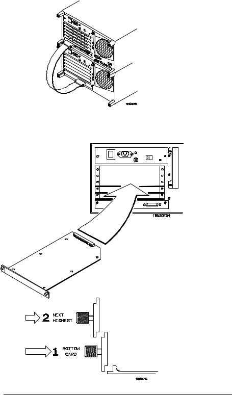
Install measurement modules in any slot
Single card analyzers, oscilloscopes, and other options can go in any slot of the HP 16500C or HP 16501A. You should generally begin installing cards starting with the bottom-most slot and working up.
Some measurement modules have multiple cards. A multiple-card module must be installed into adjacent slots in the same mainframe—that is, you cannot install one card of the module into the HP 16500C and the other into the HP 16501A.
Calibrate measurement modules after installation
Some measurement modules are sensitive to temperature and voltage variations between different mainframes. Thus, when you install such a module in the mainframe, you should calibrate it before using it to ensure maximum measurement precision and accuracy.
See the Service Guide for each measurement module for installation and calibration procedures.
ii
HP 16500C
HP 16501A
iii

iv
In This Book
This User’s Guide shows you how to use the HP 16500C Logic Analysis System in your everyday debugging work.
Chapter 1, “Triggering,” shows you how to set up the analyzer to trigger on the various kinds of events present in your system. Advanced triggering capability allows you to look at only the program states of interest when you are solving a particular problem.
Chapter 2, “Intermodule Measurements,” shows you how to configure multiple
HP 16500 modules and external measurement instruments into a single measurement system in which modules trigger each other.
Chapter 3, “File Management,” shows you how to transfer files to and from the
HP 16500C using flexible disks, LAN interfaces, and other interfaces.
Chapter 4,“Concepts,” gives you a brief introduction to the ideas underlying the trigger sequencer and the inverse assembler, two important components of sophisticated logic analysis.
Chapter 5, “Solving Problems,” shows you how to diagnose and correct the more common types of problems that might occur while you are making a measurement.
Chapter 6, “Application Notes,” lists the various application notes that HP has published regarding the HP 16500C and other similar HP logic analyzers. These notes will give you more information
1
2
3
4
5
6
Triggering
Intermodule Measurements
File Management
Concepts
Solving Problems
Application Notes
Glossary
Index
v

|
about specific application problems and how to solve them using an HP logic |
|
analyzer. |
See Also |
For general information on setup and operation of the HP 16500C, see the |
|
HP 16500C /16501A Logic Analysis System User’s Reference. |
|
For information on programming the HP 16500C using a computer controller |
|
such as a workstation or personal computer, see the HP 16500C/16501A |
|
Logic Analysis System Programmer’s Guide. The Programmer’s Guide is |
|
available from your HP Sales Office. |
|
For information on logic analyzers, oscilloscopes, preprocessors, and other |
|
logic analysis system options, see the User’s Reference manual for those |
|
options. |
vi

Contents
1 Triggering
To store and time the execution of a subroutine 1–3 To trigger on the nth iteration of a loop 1–5
To trigger on the nth recursive call of a recursive function 1–6 To trigger on entry to a function 1–8
To capture a write of known bad data to a particular variable 1–10 To trigger on a loop that occasionally runs too long 1–11
To verify that all stacks and registers are restored correctly before exiting a subroutine 1–12
To trigger after all status bus lines finish transitioning 1–13 To find the nth assertion of a chip select line 1–14
To verify that the chip select line of a memory chip is strobed after the address is stable 1–15
To trigger when expected data does not appear on the data bus from a remote device when requested 1–16
To test minimum and maximum pulse limits 1–18 To detect a handshake violation 1–20
To detect bus contention 1–21
Cross-Arming Trigger Examples 1–22
To examine software execution when a timing violation occurs 1–23 To look at control and status signals during execution of a routine 1–24
2 Intermodule Measurements
Intermodule Measurement Examples 2–4
To set up a group run of modules within the HP 16500C 2–4
To start a group run of modules from an external trigger source 2–6 To start an external instrument on command from a module within
the HP 16500 and 16501 mainframe 2–8
To see the status of a module within an intermodule measurement 2–10 To see time correlation of each module within an
intermodule measurement 2–12
To use a timing analyzer to detect a glitch 2–14 To capture the waveform of a glitch 2–15
vii

Contents
To capture state flow showing how your target system processes an interrupt 2–16
To test a circuit using stimulus-response 2–17
To use a state analyzer to trigger timing analysis of a count-down on a set of data lines 2–18
To monitor the activity of two coprocessors in a target system 2–19
Special displays 2–21
To interleave trace lists 2–22
To view trace lists and waveforms together on the same display 2–24
Skew Adjustment 2–26
To adjust for minimum skew between two modules involved in an intermodule measurement 2–27
3 File Management |
|
|
Transferring Files Using the Flexible Disk Drive |
3–3 |
|
To save a measurement configuration |
3–4 |
|
To load a measurement configuration |
3–6 |
|
To save a trace list in ASCII format 3–8 |
|
|
To save a menu or measurement as a graphic image |
3–10 |
|
To load system software 3–12 |
|
|
Using the LAN Interface |
3–13 |
To set up the HP 16500C |
3–14 |
To transfer data files from the HP 16500C system to your computer 3–16 |
|
To transfer graphics files from the HP 16500C system to your computer 3–18
viii

Contents
4Concepts
The Trigger Sequencer 4–3
The Inverse Assembler 4–10
Configuration Translation for Analyzer Modules 4–13
5If You Have a Problem
Analyzer Problems 5–3
Intermittent data errors 5–3 |
|
Unwanted triggers |
5–3 |
No Setup/Hold field on format screen 5–4 |
|
No activity on activity indicators 5–4 |
|
Capacitive loading |
5–4 |
No trace list display |
5–5 |
Preprocessor Problems 5–6
Target system will not boot up 5–6
Slow clock 5–7
Erratic trace measurements 5–7
Inverse Assembler Problems 5–9
No inverse assembly or incorrect inverse assembly 5–9
Inverse assembler will not load or run 5–10
Intermodule Measurement Problems 5–11
An event wasn’t captured by one of the modules 5–11
ix

Contents
Messages 5–12
“Default Calibration Factors Loaded” (HP 16540, 16541, and 16542) 5–12 “. . . Inverse Assembler Not Found” 5–12
“Measurement Initialization Error” 5–13 “No Configuration File Loaded” 5–14 “Selected File is Incompatible” 5–14 “Slow or Missing Clock” 5–14
“State Clock Violates Overdrive Specification” 5–15 “Time from Arm Greater Than 41.93 ms” 5–15 “Waiting for Trigger” 5–16
6Application Notes Glossary
Index
x
1
Triggering

Triggering
As you begin to understand a problem in your system, you may realize that certain conditions must occur before the problem occurs. You can use sequential triggering to ensure that those conditions have occurred before the analyzer recognizes its trigger and captures information.
You set up sequential triggering as follows:
∙Select the Trigger menu for the module you are using.
∙In the Trigger menu, define terms and associated values to be used when searching through the sequence.
∙In the Trigger menu, select the number of the state sequence level you want to modify, and enter the appropriate store qualification, sequence-advance specification, and sequence-Else specification.
If you aren’t familiar with the trigger menus, try working through the examples in the Logic Analyzer Training Kit manual, or refer to the User’s Reference for your analyzer.
1–2

Triggering
To store and time the execution of a subroutine
To store and time the execution of a subroutine
Most systems software of any kind is composed of a hierarchy of functions and procedures. During integration, testing, and performance evaluation, you will want to look at specific procedures to verify that they are executing correctly and that the implementation is efficient. The analyzer allows you to do this by triggering on entry to the address range of the subroutine and counting the elapsed time since the trigger state.
1Select the state analyzer Trigger menu.
2Set Count to Time.
Setting the Count to Time causes the state analyzer to store a time stamp for each data point that is stored in trace memory. The trace list will show these time stamps next to each state.
3Define a range term, such as Range1, to represent the address range of the subroutine of interest.
You may need to examine the structure of your code to help determine this. If your subroutine calls are really procedure calls, then there is likely to be some code at the beginning of the routine that adjusts the stack for local variable allocation. This will precede the address of the first statement in the procedure. If your subroutine has no local storage and is called by a jump or branch, then the first statement will also be the entry address.
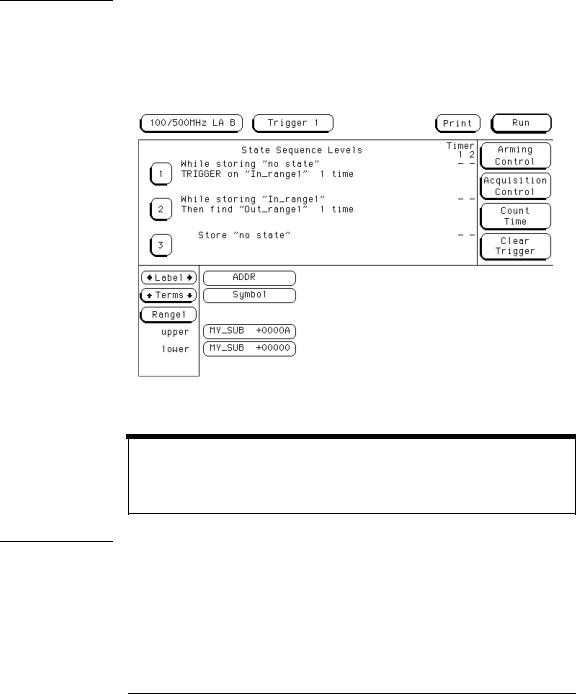
4Under State Sequence Levels, enter the following sequence specification:
∙While storing “no state” Trigger on “In_range1” 1 time
∙While storing “In_range1” Then find “Out_range1” 1 time
∙Store “no state”
1–3
Triggering
To store and time the execution of a subroutine
Example |
Suppose you want to trigger on entry to a routine called MY_SUB. You can |
|
|
define the address of MY_SUB in the Format menu, allowing you to reference |
|
|
the symbol name when setting up the trace specification. Assume that |
|
|
MY_SUB extends for 0A hex locations. You can set up the trigger sequencer |
|
|
as shown in the display. |
|
|
|
|
|
|
|
Trigger Setup for Storing Execution of a Subroutine
For processors that do prefetching of instructions or have pipelined architectures, you may want to add part or all of the depth of the pipeline to the start address for In_Range1 to ensure that the analyzer does not trigger on a prefetched but unexecuted state.
1–4

Triggering
To trigger on the nth iteration of a loop
To trigger on the nth iteration of a loop
Traditional debugging requires print statements around the area of interest. This is not possible in most embedded systems designs. But, the analyzer allows you to view the system’s behavior when a particular event occurs. Suppose that your system behaves incorrectly on the last iteration of a loop, which, in this instance, happens to be the 10th iteration. You can use the analyzer’s triggering capabilities to capture that iteration and subsequent processor activity.
1Select the state analyzer Trigger menu.
2Define the terms LP_START and LP_END to represent the start and end addresses of statements in the loop, and LP_EXIT to represent the first statement executed after the loop terminates.
3Under State Sequence Levels, enter the following sequence specification:
∙While storing “no state” Find LP_END 1 time
∙While storing “anystate” TRIGGER on LP_START 9 times; Else on “LP_EXIT” go to level 1
∙Store “anystate”
The above sequence specification has some advantages and a potential problem. The advantages are that a pipelined processor won’t trigger until it has executed the loop 10 times. Requiring LP_END to be seen at least once first ensures that the processor actually entered the loop; then, 9 more iterations of LP_START is really the 10th iteration of the loop. Also, no trigger occurs if the loop executes less than 10 times: the analyzer sees LP_EXIT and restarts the trigger sequence. The potential problem is that LP_EXIT may be too near LP_END and thus appear on the bus during a prefetch. The analyzer will constantly restart the sequence and will never trigger. The solution to this problem depends on the structure of your code. You may need to experiment with different trigger sequences to find one that captures only the data you wish to view.
1–5

Triggering
To trigger on the nth recursive call of a recursive function
To trigger on the nth recursive call of a recursive function
1Select the state analyzer Trigger menu.
2Define the terms CALL_ADD, F_START, and F_END to represent the called address of the recursive function, and the start and end addresses of the function. Define F_EXIT to represent the address of the first program statement executed after the original recursive call has terminated.
Typically, CALL_ADD is the address of the code that sets up the activation record on the stack, F_START is the address of the first statement in the function, and F_END is the address of the last instruction of the function, which does not necessarily correspond to the address of the last statement. If the start of the function and the address called by recursive calls are the same, or you are not interested in the function initialization code, you can use F_START for both CALL_ADD and F_START.
3Under State Sequence Levels, enter the following sequence specification:
∙While storing “no state” Find “F_END” 1 time
∙While storing “anystate” Then find “F_START” 1 time
∙While storing “anystate” TRIGGER on “CALL_ADD” 20 times Else on “F_EXIT” go to level 1
∙Store “anystate”
As with the trigger specification for “To trigger on the nth iteration of a loop,” this specification helps avoid potential problems on pipelined processors by requiring that the processor already be in the first recursive call before advancing the sequencer. Because it is already in the first recursive call, this example triggers on the 21st recursive call, which is the 22nd entrance to the function. Depending on the exact code used for the calls, you may need to experiment with different trigger sequences to find one that captures only the data you wish to view.
1–6

Triggering
To trigger on the nth recursive call of a recursive function
Triggering on the 22nd Call of a Recursive Function
1–7

Triggering
To trigger on entry to a function
To trigger on entry to a function
This sequence triggers on entry to a function only when it is called by one particular function.
1Select the state analyzer Trigger menu.
2Define the terms F1_START and F1_END to represent the start and end addresses of the calling function. Define F2_START to represent the start address of the called function.
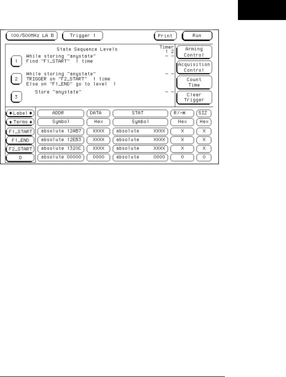
3Under State Sequence Levels, enter the following sequence specification:
∙While storing “anystate” Find “F1_START” 1 time
∙While storing “anystate” TRIGGER on “F2_START” 1 time Else on “F1_END” go to level 1
∙Store “anystate”
This sequence specification assumes there is some conditional logic in function F1 that chooses whether or not to call function F2. Thus, if F1 ends without the analyzer having seen F2, the sequence restarts.
The specification also stores all execution inside function F1, whether or not F2 was called. If you are interested only in the execution of F1, without the code that led to its invocation, you can change the storage specification from “anystate” to “nostate” for the second sequence term.
1–8
Triggering
To trigger on entry to a function
Triggering on Entry to a Function
1–9
Triggering
To capture a write of known bad data to a particular variable
To capture a write of known bad data to a particular variable
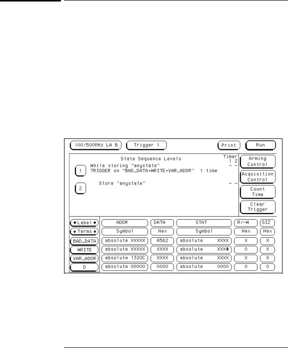
The trigger specification ANDs the bad data on the data bus, write transaction on the status bus, and address of the variable on the address bus.
1Select the state analyzer Trigger menu.
2Define the terms BAD_DATA, WRITE, and VAR_ADDR to represent the bad data value, write status, and the address of the variable.
3Under State Sequence Levels, enter the following sequence specification:
∙While storing “anystate” TRIGGER on “BAD_DATA ∙ WRITE ∙ VAR_ADDR” one time (you use the Combination trigger term to do this)
∙Store “anystate”
Capturing a Bad Write to a Variable
1–10
Triggering
To trigger on a loop that occasionally runs too long
To trigger on a loop that occasionally runs too long
This example assumes the loop normally executes in 14 μs.
1Select the state analyzer Trigger menu.
2Define terms LP_START, LP_END, and Timer1 to represent the start and end addresses of the loop, and the normal duration of the loop.
You can make the sequence specification closer to the problem domain by renaming Timer1 to LOOP_DUR.
3Under State Sequence Levels, enter the following sequence specification:
∙While storing “anystate” Find “LP_START” 1 time
∙While storing “anystate” TRIGGER on “LOOP_DUR 14.00 μs” 1 time Else on “LP_END” go to level 1
You will need to start the LOOP_DUR timer (Timer1) upon entering this state. You do this using the Timer Control field in the menu for sequence level 2.
∙Store “anystate”
Triggering on a Loop Overrun
1–11

Triggering
To verify that all stacks and registers are restored correctly before exiting a subroutine
To verify that all stacks and registers are restored correctly before exiting a subroutine
The exit code for a function will often contain instructions for deallocating stack storage for local variables and restoring registers that were saved during the function call. Some language implementations vary on these points, with the calling function doing some of this work, so you may need to adapt the procedure to suit your system.
1Select the state analyzer Trigger menu.
2Define terms SR_START and SR_END to represent the start and end addresses of the subroutine.
3Under State Sequence Levels, enter the following sequence specification:
∙While storing “anystate” Find “SR_START” 1 time
∙While storing “anystate” Then find “SR_END” 1 time
∙While storing “anystate” TRIGGER on “¹ SR_START” 1 time Else on “SR_START” go to level 2
∙Store “anystate”
Verifying Correct Return from a Function Call
1–12
Triggering
To trigger after all status bus lines finish transitioning
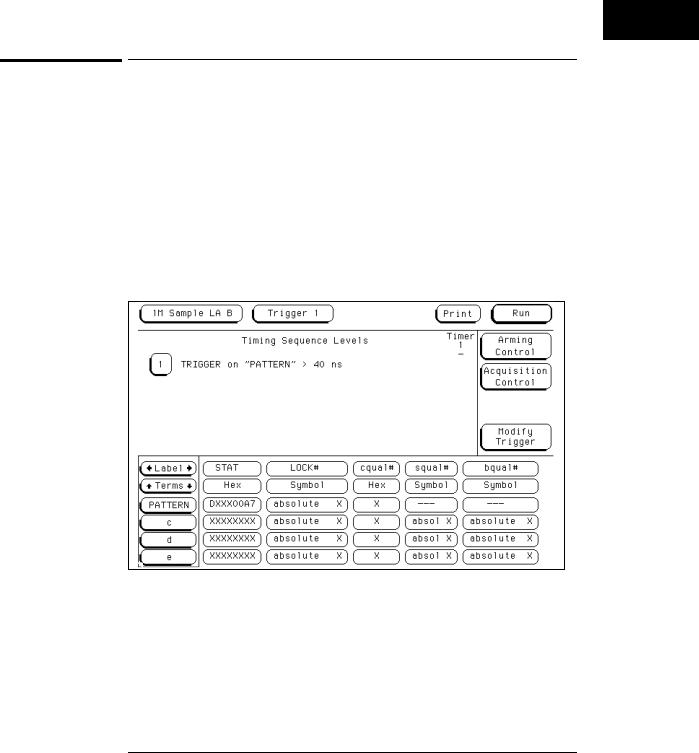
To trigger after all status bus lines finish transitioning
In some applications, you will want to trigger a measurement when a particular pattern has become stable. For example, you might want to trigger the analyzer when a microprocessor’s status bus has become stable during the bus cycle.
1Select the timing analyzer Trigger menu and define a term called PATTERN to represent the value to be found on the label representing the status bus lines.
2Under Timing Sequence Levels, enter the following sequence specification:
TRIGGER on “PATTERN” > 40 ns
Triggering after lines are done transitioning
1–13
Triggering
To find the nth assertion of a chip select line
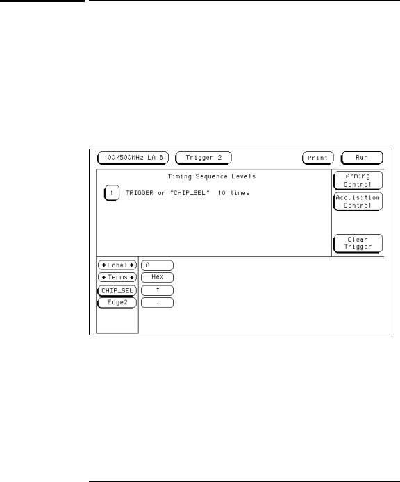
To find the nth assertion of a chip select line
1Select the timing analyzer Trigger menu.
2Define the glitch/edge1 term to represent the asserting transition on the chip select line.
You can rename the Edge1 term to make it correspond more closely to the problem domain, for example, to CHIP_SEL.
3Under Timing Sequence Levels, enter the following sequence specification:
TRIGGER on “CHIP_SEL” 10 times
Triggering on the 10th Assertion of a Chip Select Line
1–14
Triggering
To verify that the chip select line of a memory chip is strobed after the address is stable
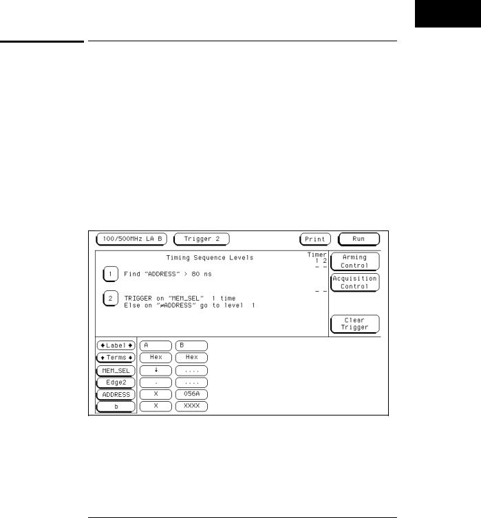
To verify that the chip select line of a memory chip is strobed after the address is stable
1Select the timing analyzer Trigger menu.
2Define a term called ADDRESS to represent the address in question and the Edge1 term to represent the asserting transition on the chip select line.
You can rename the Edge1 term to suit the problem, for example, to MEM_SEL.
3Under Timing Sequence Levels, enter the following sequence specification:
∙Find “ADDRESS” > 80 ns
∙TRIGGER on “MEM_SEL” 1 time Else on “¹ ADDRESS” go to level 1
Verifying Setup Time for Memory Address
1–15

Triggering
To trigger when expected data does not appear on the data bus from a remote device when requested
To trigger when expected data does not appear on the data bus from a remote device when requested
1Select the timing analyzer Trigger menu.
2Define a term called DATA to represent the expected data, the Edge1 term to represent the chip select line of the remote device, and the Timer1 term to identify the time limit for receiving expected data.
You can rename the Edge1 and Timer1 terms to match the problem domain, for example, to REM_SEL and ACK_TIME.
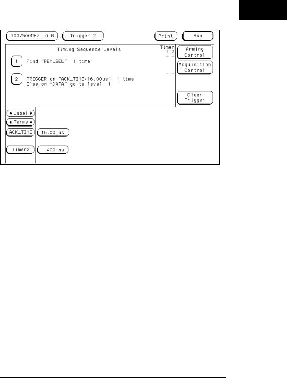
3Under Timing Sequence Levels, enter the following sequence specification:
∙Find “REM_SEL” 1 time
∙TRIGGER on “ACK_TIME > 16.00 μs” 1 time Else on “DATA” go to level 1
You will need to use the Timer Control field in the sequence setup for sequence level 2 to start the ACK_TIME timer upon entering that sequence level.
This sequence specification causes the analyzer to trigger when the data does not occur in 16 μs or less. If it does occur within 16 μs, the sequence restarts. Specifications of this type are useful in finding intermittent problems. You can set up and run the trace, then cycle the system through temperature and voltage variations, using automatic equipment if necessary. The failure will be captured and saved for later review.
1–16
Triggering
To trigger when expected data does not appear on the data bus from a remote device when requested
Triggering When I/O Data Not Returned
1–17
Triggering
To test minimum and maximum pulse limits
To test minimum and maximum pulse limits
1Select the timing analyzer Trigger menu.
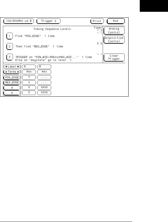
2Define the Edge1 term to represent the positive-going transition, and define the Edge2 term to represent the negative-going transition on the line with the pulse to be tested.
You can rename these terms to POS_EDGE and NEG_EDGE.
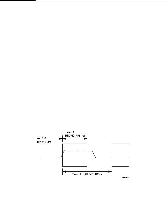
3Define the Timer1 term to represent the minimum pulse width, and the Timer2 term to represent the maximum pulse width.
You can rename these terms to MIN_WID and MAX_WID. In this example, Timer1 was set to 496 ns and Timer2 was set to 1 μs. Both timers start when sequence level 2 is active.
4Under Timing Sequence Levels, enter the following sequence specification:
∙Find “POS_EDGE” 1 time
∙Then find “NEG_EDGE” 1 time
∙TRIGGER on “MIN_WID 496 ns + MAX_WID 1.00 μs” 1 time Else on “anystate” go to level 1
Because both timers start when entering sequence level 2, they start as soon as the positive edge of the pulse occurs. Once the negative edge occurs, the sequencer transitions to level 3. If at that point, the MIN_WID timer is less than 496 ns or the MAX_WID timer is greater than 1 μs, the pulse width has been violated and the analyzer should trigger. Otherwise, the sequence is restarted.
Measurement of Minimum and Maximum Pulse Width Limits
1–18
Triggering
To test minimum and maximum pulse limits
Triggering when a Pulse Exceeds Minimum or Maximum Limits
1–19
Triggering
To detect a handshake violation
To detect a handshake violation
1Select the timing analyzer Trigger menu.
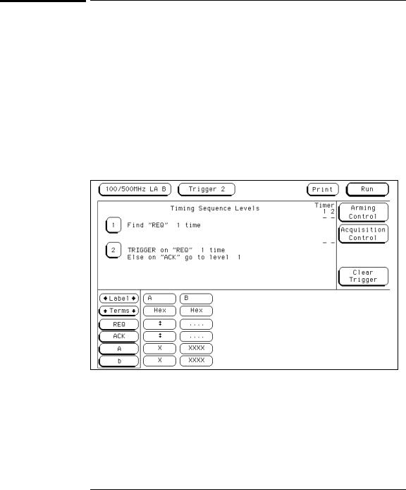
2Define the Edge1 term to represent either transition on the first handshake line, and the Edge2 term to represent either transition on the second handshake line.
You can rename these terms to match your problem, for example, to REQ and ACK.
3Under Timing Sequence Levels, enter the following sequence specification:
∙Find “REQ” 1 time
∙TRIGGER on “REQ” 1 time Else on “ACK” go to level 1
Triggering on a Handshake Violation
1–20
Loading...