


HP 12076A LAN/1000 Link
Node Manager's Manual
Software Services and Technology Division
11000 Wolfe Road
Cupertino, CA 95014%9804
Manual Part No.12076790002 |
Printed in U.S.A. March, 1994 |
E0394 |
Second Edition |

NOTICE
The information contained in this document is subject to change without notice.
HEWLETT7PACKARD MAKES NO WARRANTY OF ANY KIND WITH REGARD TO THE MATERIAL, INCLUDING, BUT NOT LIMITED TO, THE IMPLIED WARRANTIES OF MERCHANTABILITY AND FITNESS FOR A PARTICULAR PURPOSE. Hewlett7Packard shall not be liable for errors contained herein or for incidental or consequential damages in connection with the furnishing, performance, or use of this material.
Hewlett7Packard assumes no responsibility for the use or reliability of its software on equipment that is not furnished by Hewlett7Packard.
This document contains proprietary information which is protected by copyright. All rights are reserved. No part of this document may be photocopied, reproduced, or translated to another language without the prior written consent of Hewlett7P ackard Company.
RESTRICTED RIGHTS LEGEND
Use, duplication, or disclosure by the Government is subject to restrictions as set forth in subparagraph (c) (1) (ii) of the Rights in Technical Data and Computer Software clause at
DFARs 252.227.7013.
Copyright E 198571987,1994 by Hewlett7Packard Company
2

Printing History
The Printing History below identifies the edition of this manual and any updates that are included. Periodically, update packages are distributed that contain replacement pages to be merged into the manual, including an updated copy of this printing history page. Also, the update may contain write7in instructions.
Each reprinting of this manual will incorporate all past updates; however, no new information will be added. Thus, the reprinted copy will be identical in content to prior printings of the same edition with its user7inserted update information. New editions of this manual will contain new information, as well as all updates.
First Edition . . . . . . . . . . . . . . . . . . Nov 1985
Update 1 . . . . . . . . . . . . . . . . . . Dec 1986
Update 2 . . . . . . . . . . . . . . . . . . Sep 1987
Second Edition . . . . . . . . . . . . . . . Mar 1994
. . . . . . . . . . . . . . . . . . . . . . . . . . . . . . . . . . . . . .
. . . . . . . . . . . . . . . . . . . . . . . . . . . . . . . . . . . . . .
. . . . . . . . . . . . . . . . . . . . . . . . . . . . . . . . . . . . . .
. . . . . . . . . . . . . . . . . . . . . . . . . . . . . . . . . . . . . .
3/4


Preface
Purpose
This manual describes the HP Node Manager software provided with the HP 92077A RTE"A product. The Node Manager software is used with the ID*67 driver and HP 12076A LAN/1000 Link product. It is intended for network and system managers, and system support personnel, who are required to implement and maintain an IEEE 802.2/802.3 Local Area Network (LAN) consisting of HP 1000 A"Series computers.
With the information contained in this manual, the Node Manager software can be installed and used to configure nodes on the LAN, log certain events, gather node statistics for network use, and perform limited diagnostics.
Caution There is no security provided by the Node Manager software other than what is available through the RTE"A Operating System. Users of Node Manager software have access to commands that can cause communication failure between nodes, and can render network services inoperative. Limited and controlled access to Node Manager software is recommended.
Assumptions
This manual is intended for System Managers or Support personnel who will install or maintain HP 1000 A"Series computers on an IEEE 802.3 Local Area Network. A working knowledge of the RTE"A Operating System and the IEEE 802.2/802.3 standards is presumed.
Related Reading
The following documents should be available as a reference when reading this manual (system manuals were provided with your system). Additional copies may be obtained from Hewlett"Packard Software Materials Operation (SMO), or through your nearest HP Sales and Support Office:
RTE A System Design Manual, part number 92077"90013
RTE A System Generation and Installation Manual, part number 92077"90034
RTE A User's Manual, part number 92077"90002
5

HP 12076A LAN/1000 Link Local Area Network Interface Controller Installation Manual, part number 12076"90001
In addition, a library of data communications publications starting with the latest editions of the IEEE 802.2 and 802.3 Standards will be helpful. For information, contact:
Institute of Electrical and Electronics Engineers, Inc.
345 East 47th Street
New York, N.Y. 10017 U.S.A.
Organization
This manual is organized as follows:
Section 1 |
introduces the Node Manager software. Along with system requirements, |
|
general features and implementation considerations of the software are |
|
provided. |
Section 2 |
positions the Hewlett"Packard offering within the framework of the Open |
|
Systems Interconnection Reference model and the IEEE 802.2 and 802.3 |
|
standards. Transmission frame (packet) structure under the IEEE |
|
standards is reviewed. Much of the terminology here is used throughout |
|
this manual. |
Section 3 |
discusses LAN driver and Node Manager software installation. |
Section 4 |
describes the structure and operation of Node Manager software. |
Section 5 |
describes the use of Node Manager software. Each of the Node Manager |
|
commands and parameter entries is provided. |
Section 6 |
describes remote LANVCP operations. It discusses the software and |
|
procedures for downloading a memory"based system to another computer, |
|
and for using the remote VCP over the LAN. |
Appendix A |
provides error codes and descriptions for errors returned by the Node |
|
Manager software, the LAN driver, and the LANVCP software. |
Appendix B |
provides the screen listing contained in the HELP menu. This listing of the |
|
Node Manager software command summary may be used for quick |
|
reference. |
Appendix C |
illustrates the relationship among the IEEE 802 family of standards. |
Appendix D |
provides a history of changes to this manual in summary format. |
6

Table of Contents
Chapter 1
Introduction
Identification . . . . . . . . . . . . . . . . . . . . . . . . . . . . . . . . . . . . . . . . . . . . . . . . . . . . . . . . . . . . . . . |
1"1 |
Installation . . . . . . . . . . . . . . . . . . . . . . . . . . . . . . . . . . . . . . . . . . . . . . . . . . . . . . . . . . . . . . . . . |
1"1 |
System Requirements . . . . . . . . . . . . . . . . . . . . . . . . . . . . . . . . . . . . . . . . . . . . . . . . . . . . . . . . |
1"1 |
Hardware . . . . . . . . . . . . . . . . . . . . . . . . . . . . . . . . . . . . . . . . . . . . . . . . . . . . . . . . . . . . . . |
1"1 |
Software . . . . . . . . . . . . . . . . . . . . . . . . . . . . . . . . . . . . . . . . . . . . . . . . . . . . . . . . . . . . . . . |
1"3 |
System Memory . . . . . . . . . . . . . . . . . . . . . . . . . . . . . . . . . . . . . . . . . . . . . . . . . . . . . |
1"4 |
LANVCP Operation . . . . . . . . . . . . . . . . . . . . . . . . . . . . . . . . . . . . . . . . . . . . . . . . . |
1"5 |
Node Manager Software Services . . . . . . . . . . . . . . . . . . . . . . . . . . . . . . . . . . . . . . . . . . . . . . |
1"5 |
Configuration Services . . . . . . . . . . . . . . . . . . . . . . . . . . . . . . . . . . . . . . . . . . . . . . . . . . . . |
1"6 |
Statistical Services . . . . . . . . . . . . . . . . . . . . . . . . . . . . . . . . . . . . . . . . . . . . . . . . . . . . . . . |
1"6 |
Diagnostic Services . . . . . . . . . . . . . . . . . . . . . . . . . . . . . . . . . . . . . . . . . . . . . . . . . . . . . . |
1"6 |
Event Logging Services . . . . . . . . . . . . . . . . . . . . . . . . . . . . . . . . . . . . . . . . . . . . . . . . . . . |
1"6 |
Implementation Considerations . . . . . . . . . . . . . . . . . . . . . . . . . . . . . . . . . . . . . . . . . . . . . . . . |
1"7 |
Designating Nodes . . . . . . . . . . . . . . . . . . . . . . . . . . . . . . . . . . . . . . . . . . . . . . . . . . . . . . . |
1"8 |
Chapter 2
General Information
Open Systems Interconnection Model . . . . . . . . . . . . . . . . . . . . . . . . . . . . . . . . . . . . . . . . . . |
2"1 |
IEEE 802 Service Types . . . . . . . . . . . . . . . . . . . . . . . . . . . . . . . . . . . . . . . . . . . . . . . . . . . . . . |
2"3 |
Transmission Frames . . . . . . . . . . . . . . . . . . . . . . . . . . . . . . . . . . . . . . . . . . . . . . . . . . . . . . . . . |
2"3 |
Format . . . . . . . . . . . . . . . . . . . . . . . . . . . . . . . . . . . . . . . . . . . . . . . . . . . . . . . . . . . . . . . . . |
2"4 |
Field Definitions . . . . . . . . . . . . . . . . . . . . . . . . . . . . . . . . . . . . . . . . . . . . . . . . . . . . . . . . |
2"5 |
Preamble . . . . . . . . . . . . . . . . . . . . . . . . . . . . . . . . . . . . . . . . . . . . . . . . . . . . . . . . . . . |
2"5 |
Start Frame Delimiter . . . . . . . . . . . . . . . . . . . . . . . . . . . . . . . . . . . . . . . . . . . . . . . . |
2"5 |
Destination Address . . . . . . . . . . . . . . . . . . . . . . . . . . . . . . . . . . . . . . . . . . . . . . . . . . |
2"5 |
Source Address . . . . . . . . . . . . . . . . . . . . . . . . . . . . . . . . . . . . . . . . . . . . . . . . . . . . . . |
2"7 |
Length . . . . . . . . . . . . . . . . . . . . . . . . . . . . . . . . . . . . . . . . . . . . . . . . . . . . . . . . . . . . . |
2"7 |
Protocol Data Unit . . . . . . . . . . . . . . . . . . . . . . . . . . . . . . . . . . . . . . . . . . . . . . . . . . . |
2"8 |
Destination Service Access Point (DSAP) Address . . . . . . . . . . . . . . . . . . . . |
2"8 |
Source Service Access Point (SSAP) Address . . . . . . . . . . . . . . . . . . . . . . . . . |
2"10 |
Control . . . . . . . . . . . . . . . . . . . . . . . . . . . . . . . . . . . . . . . . . . . . . . . . . . . . . . . . . |
2"11 |
Information . . . . . . . . . . . . . . . . . . . . . . . . . . . . . . . . . . . . . . . . . . . . . . . . . . . . . |
2"13 |
Pad . . . . . . . . . . . . . . . . . . . . . . . . . . . . . . . . . . . . . . . . . . . . . . . . . . . . . . . . . . . . . . . . |
2"15 |
Frame Check Sequence . . . . . . . . . . . . . . . . . . . . . . . . . . . . . . . . . . . . . . . . . . . . . . . |
2"15 |
Invalid Frames . . . . . . . . . . . . . . . . . . . . . . . . . . . . . . . . . . . . . . . . . . . . . . . . . . . . . . . . . . |
2"15 |
Chapter 3
Software Installation
Installation Summary . . . . . . . . . . . . . . . . . . . . . . . . . . . . . . . . . . . . . . . . . . . . . . . . . . . . . . . . |
3"2 |
Modules Provided . . . . . . . . . . . . . . . . . . . . . . . . . . . . . . . . . . . . . . . . . . . . . . . . . . . . . . . . . . . |
3"3 |
Answer File Entries . . . . . . . . . . . . . . . . . . . . . . . . . . . . . . . . . . . . . . . . . . . . . . . . . . . . . . . . . . |
3"3 |
System Relocation . . . . . . . . . . . . . . . . . . . . . . . . . . . . . . . . . . . . . . . . . . . . . . . . . . . . . . . |
3"3 |
Driver Relocation . . . . . . . . . . . . . . . . . . . . . . . . . . . . . . . . . . . . . . . . . . . . . . . . . . . . . . . . |
3"3 |
Table Generation . . . . . . . . . . . . . . . . . . . . . . . . . . . . . . . . . . . . . . . . . . . . . . . . . . . . . . . . |
3"4 |
7

Memory Allocation . . . . . . . . . . . . . . . . . . . . . . . . . . . . . . . . . . . . . . . . . . . . . . . . . . . . . . |
3"6 |
Generate the New System . . . . . . . . . . . . . . . . . . . . . . . . . . . . . . . . . . . . . . . . . . . . . . . . . |
3"6 |
Linking Node Manager Software . . . . . . . . . . . . . . . . . . . . . . . . . . . . . . . . . . . . . . . . . . . . . . . |
3"6 |
Security/1000 . . . . . . . . . . . . . . . . . . . . . . . . . . . . . . . . . . . . . . . . . . . . . . . . . . . . . . . . . . . . |
3"6 |
Using LAN8023.CMD . . . . . . . . . . . . . . . . . . . . . . . . . . . . . . . . . . . . . . . . . . . . . . . . . . . . |
3"7 |
Driver and Node Manager Initialization . . . . . . . . . . . . . . . . . . . . . . . . . . . . . . . . . . . . . . . . . |
3"8 |
Verifying the System . . . . . . . . . . . . . . . . . . . . . . . . . . . . . . . . . . . . . . . . . . . . . . . . . . . . . . . . . |
3"9 |
Chapter 4
Node Manager Operations
Node Manager Modules . . . . . . . . . . . . . . . . . . . . . . . . . . . . . . . . . . . . . . . . . . . . . . . . . . . . . . |
4"1 |
Command Processing . . . . . . . . . . . . . . . . . . . . . . . . . . . . . . . . . . . . . . . . . . . . . . . . . . . . . . . . |
4"2 |
NM and NM2 Modules . . . . . . . . . . . . . . . . . . . . . . . . . . . . . . . . . . . . . . . . . . . . . . . . . . . |
4"2 |
Command Entry Errors . . . . . . . . . . . . . . . . . . . . . . . . . . . . . . . . . . . . . . . . . . . . . . . |
4"2 |
NMGR Module . . . . . . . . . . . . . . . . . . . . . . . . . . . . . . . . . . . . . . . . . . . . . . . . . . . . . . . . . |
4"3 |
Command Execution Errors . . . . . . . . . . . . . . . . . . . . . . . . . . . . . . . . . . . . . . . . . . . |
4"3 |
Files and Directories . . . . . . . . . . . . . . . . . . . . . . . . . . . . . . . . . . . . . . . . . . . . . . . . . . . . . . . . . |
4"4 |
Root Directory . . . . . . . . . . . . . . . . . . . . . . . . . . . . . . . . . . . . . . . . . . . . . . . . . . . . . . . . . . |
4"5 |
Help Menu . . . . . . . . . . . . . . . . . . . . . . . . . . . . . . . . . . . . . . . . . . . . . . . . . . . . . . . . . . . . . |
4"5 |
Link File Directories . . . . . . . . . . . . . . . . . . . . . . . . . . . . . . . . . . . . . . . . . . . . . . . . . . . . . |
4"5 |
MCAST.TXT . . . . . . . . . . . . . . . . . . . . . . . . . . . . . . . . . . . . . . . . . . . . . . . . . . . . . . . . |
4"5 |
EL.TXT . . . . . . . . . . . . . . . . . . . . . . . . . . . . . . . . . . . . . . . . . . . . . . . . . . . . . . . . . . . . |
4"7 |
Driver Interface . . . . . . . . . . . . . . . . . . . . . . . . . . . . . . . . . . . . . . . . . . . . . . . . . . . . . . . . . . . . . |
4"8 |
Logical Units . . . . . . . . . . . . . . . . . . . . . . . . . . . . . . . . . . . . . . . . . . . . . . . . . . . . . . . . . . . |
4"8 |
Writing Packets . . . . . . . . . . . . . . . . . . . . . . . . . . . . . . . . . . . . . . . . . . . . . . . . . . . . . . . . . . |
4"8 |
Reading Packets . . . . . . . . . . . . . . . . . . . . . . . . . . . . . . . . . . . . . . . . . . . . . . . . . . . . . . . . . |
4"8 |
Driver's Class Table . . . . . . . . . . . . . . . . . . . . . . . . . . . . . . . . . . . . . . . . . . . . . . . . . . |
4"8 |
Packet Routing . . . . . . . . . . . . . . . . . . . . . . . . . . . . . . . . . . . . . . . . . . . . . . . . . . . . . . |
4"9 |
Saving Orphan Packets . . . . . . . . . . . . . . . . . . . . . . . . . . . . . . . . . . . . . . . . . . . . . . . . . . . |
4"10 |
LANIC Card Configuration Data . . . . . . . . . . . . . . . . . . . . . . . . . . . . . . . . . . . . . . . . . . |
4"11 |
RAM & NOVRAM . . . . . . . . . . . . . . . . . . . . . . . . . . . . . . . . . . . . . . . . . . . . . . . . . . |
4"11 |
Driver's Copy . . . . . . . . . . . . . . . . . . . . . . . . . . . . . . . . . . . . . . . . . . . . . . . . . . . . . . . |
4"12 |
Node Manager Software Initialization . . . . . . . . . . . . . . . . . . . . . . . . . . . . . . . . . . . . . . . . . . |
4"13 |
Posting Its Class Number . . . . . . . . . . . . . . . . . . . . . . . . . . . . . . . . . . . . . . . . . . . . . . . . . |
4"13 |
Finding Link File Directories . . . . . . . . . . . . . . . . . . . . . . . . . . . . . . . . . . . . . . . . . . . . . . |
4"15 |
Other Initialization Considerations . . . . . . . . . . . . . . . . . . . . . . . . . . . . . . . . . . . . . . . . . |
4"16 |
Entering User Commands . . . . . . . . . . . . . . . . . . . . . . . . . . . . . . . . . . . . . . . . . . . . . |
4"16 |
Initialization Errors . . . . . . . . . . . . . . . . . . . . . . . . . . . . . . . . . . . . . . . . . . . . . . . . . . |
4"16 |
Post Initialization . . . . . . . . . . . . . . . . . . . . . . . . . . . . . . . . . . . . . . . . . . . . . . . . . . . . |
4"17 |
Packet Filter Addressing Modes . . . . . . . . . . . . . . . . . . . . . . . . . . . . . . . . . . . . . . . . . . . . . . . |
4"18 |
Multiple LANIC Cards . . . . . . . . . . . . . . . . . . . . . . . . . . . . . . . . . . . . . . . . . . . . . . . . . . . . . . . |
4"20 |
Disk Access . . . . . . . . . . . . . . . . . . . . . . . . . . . . . . . . . . . . . . . . . . . . . . . . . . . . . . . . . . . . . |
4"20 |
Command Routing . . . . . . . . . . . . . . . . . . . . . . . . . . . . . . . . . . . . . . . . . . . . . . . . . . . . . . . |
4"20 |
Chapter 5
Using Node Manager
Parameter Notation . . . . . . . . . . . . . . . . . . . . . . . . . . . . . . . . . . . . . . . . . . . . . . . . . . . . . . . . . . |
5"1 |
Getting Started . . . . . . . . . . . . . . . . . . . . . . . . . . . . . . . . . . . . . . . . . . . . . . . . . . . . . . . . . . . . . . |
5"2 |
Running the Node Manager Software . . . . . . . . . . . . . . . . . . . . . . . . . . . . . . . . . . . . . . . |
5"2 |
Exiting the Node Manager Software . . . . . . . . . . . . . . . . . . . . . . . . . . . . . . . . . . . . . . . . |
5"3 |
Using the Help Facility . . . . . . . . . . . . . . . . . . . . . . . . . . . . . . . . . . . . . . . . . . . . . . . . . . . |
5"3 |
Entering Commands . . . . . . . . . . . . . . . . . . . . . . . . . . . . . . . . . . . . . . . . . . . . . . . . . . . . . |
5"4 |
Using the Command Stack . . . . . . . . . . . . . . . . . . . . . . . . . . . . . . . . . . . . . . . . . . . . |
5"4 |
8

Error Messages . . . . . . . . . . . . . . . . . . . . . . . . . . . . . . . . . . . . . . . . . . . . . . . . . . . . . . . . . . |
5"5 |
Command Entry . . . . . . . . . . . . . . . . . . . . . . . . . . . . . . . . . . . . . . . . . . . . . . . . . . . . . |
5"5 |
Timeout Error Messages . . . . . . . . . . . . . . . . . . . . . . . . . . . . . . . . . . . . . . . . . . . . . . |
5"6 |
Command Execution . . . . . . . . . . . . . . . . . . . . . . . . . . . . . . . . . . . . . . . . . . . . . . . . . |
5"6 |
Node Manager Commands . . . . . . . . . . . . . . . . . . . . . . . . . . . . . . . . . . . . . . . . . . . . . . . . . . . . |
5"7 |
Parameter Defaults . . . . . . . . . . . . . . . . . . . . . . . . . . . . . . . . . . . . . . . . . . . . . . . . . . . . . . |
5"7 |
Group I: Commands Not Containing the FileAddress Parameter . . . . . . . . . . . |
5"8 |
Group II: Commands Containing the FileAddress Parameter . . . . . . . . . . . . . . |
5"9 |
Retrieving the ADR Parameter . . . . . . . . . . . . . . . . . . . . . . . . . . . . . . . . . . . . . . . . |
5"10 |
Configuration Commands . . . . . . . . . . . . . . . . . . . . . . . . . . . . . . . . . . . . . . . . . . . . . . . . . . . . . |
5"10 |
Read Link Configuration Command (RC) . . . . . . . . . . . . . . . . . . . . . . . . . . . . . . . . . . . . . . . |
5"11 |
Multicast Address Considerations . . . . . . . . . . . . . . . . . . . . . . . . . . . . . . . . . . . . . . |
5"11 |
RC Command Examples . . . . . . . . . . . . . . . . . . . . . . . . . . . . . . . . . . . . . . . . . . . . . . |
5"13 |
Set Link Configuration Command (SC) . . . . . . . . . . . . . . . . . . . . . . . . . . . . . . . . . . . . . |
5"17 |
Station Address Considerations . . . . . . . . . . . . . . . . . . . . . . . . . . . . . . . . . . . . . . . . |
5"19 |
Download Server Station Address Considerations . . . . . . . . . . . . . . . . . . . . . . . . . |
5"20 |
File Server Station Address Considerations . . . . . . . . . . . . . . . . . . . . . . . . . . . . . . |
5"20 |
Packet Filter Mode Considerations . . . . . . . . . . . . . . . . . . . . . . . . . . . . . . . . . . . . . |
5"20 |
SC Command Examples . . . . . . . . . . . . . . . . . . . . . . . . . . . . . . . . . . . . . . . . . . . . . . |
5"21 |
Update Link Configuration Command (UC) . . . . . . . . . . . . . . . . . . . . . . . . . . . . . . . . . |
5"22 |
UC Command Example . . . . . . . . . . . . . . . . . . . . . . . . . . . . . . . . . . . . . . . . . . . . . . |
5"24 |
Insert Multicast Address Command (IM) . . . . . . . . . . . . . . . . . . . . . . . . . . . . . . . . . . . . |
5"25 |
IM Command Examples . . . . . . . . . . . . . . . . . . . . . . . . . . . . . . . . . . . . . . . . . . . . . . |
5"26 |
Delete Multicast Address Command (DM) . . . . . . . . . . . . . . . . . . . . . . . . . . . . . . . . . . |
5"27 |
DM Command Examples . . . . . . . . . . . . . . . . . . . . . . . . . . . . . . . . . . . . . . . . . . . . . |
5"28 |
Create Link File Directories Command (CD) . . . . . . . . . . . . . . . . . . . . . . . . . . . . . . . . |
5"29 |
CD Command Example . . . . . . . . . . . . . . . . . . . . . . . . . . . . . . . . . . . . . . . . . . . . . . . |
5"30 |
Purge Link File Directories Command (PD) . . . . . . . . . . . . . . . . . . . . . . . . . . . . . . . . . |
5"31 |
PD Command Example . . . . . . . . . . . . . . . . . . . . . . . . . . . . . . . . . . . . . . . . . . . . . . . |
5"32 |
Check Link File Existence Command (CK) . . . . . . . . . . . . . . . . . . . . . . . . . . . . . . . . . . |
5"32 |
CK Command Examples . . . . . . . . . . . . . . . . . . . . . . . . . . . . . . . . . . . . . . . . . . . . . . |
5"33 |
Diagnostic Commands . . . . . . . . . . . . . . . . . . . . . . . . . . . . . . . . . . . . . . . . . . . . . . . . . . . . . . . . |
5"34 |
The Rep Parameter . . . . . . . . . . . . . . . . . . . . . . . . . . . . . . . . . . . . . . . . . . . . . . . . . . |
5"34 |
LANIC Self"Test Command (TC) . . . . . . . . . . . . . . . . . . . . . . . . . . . . . . . . . . . . . . . . . . |
5"35 |
TC Command Examples . . . . . . . . . . . . . . . . . . . . . . . . . . . . . . . . . . . . . . . . . . . . . . |
5"36 |
Do External Loopback to MAU Command (EL) . . . . . . . . . . . . . . . . . . . . . . . . . . . . . |
5"38 |
EL Command Examples . . . . . . . . . . . . . . . . . . . . . . . . . . . . . . . . . . . . . . . . . . . . . . |
5"39 |
Issue TEST Loopback Command (TEST) . . . . . . . . . . . . . . . . . . . . . . . . . . . . . . . . . . . |
5"41 |
DSAP Considerations . . . . . . . . . . . . . . . . . . . . . . . . . . . . . . . . . . . . . . . . . . . . . . . . |
5"42 |
Self"Addressed TEST Packets . . . . . . . . . . . . . . . . . . . . . . . . . . . . . . . . . . . . . . . . . . |
5"42 |
Errors . . . . . . . . . . . . . . . . . . . . . . . . . . . . . . . . . . . . . . . . . . . . . . . . . . . . . . . . . . . . . . |
5"42 |
TEST Command Examples . . . . . . . . . . . . . . . . . . . . . . . . . . . . . . . . . . . . . . . . . . . . |
5"42 |
XID Command (XID) . . . . . . . . . . . . . . . . . . . . . . . . . . . . . . . . . . . . . . . . . . . . . . . . . . . . |
5"44 |
DSAP Considerations . . . . . . . . . . . . . . . . . . . . . . . . . . . . . . . . . . . . . . . . . . . . . . . . |
5"45 |
Self"Addressed XID Packets . . . . . . . . . . . . . . . . . . . . . . . . . . . . . . . . . . . . . . . . . . . |
5"45 |
Errors . . . . . . . . . . . . . . . . . . . . . . . . . . . . . . . . . . . . . . . . . . . . . . . . . . . . . . . . . . . . . . |
5"45 |
XID Command Examples . . . . . . . . . . . . . . . . . . . . . . . . . . . . . . . . . . . . . . . . . . . . . |
5"46 |
Event Log Commands . . . . . . . . . . . . . . . . . . . . . . . . . . . . . . . . . . . . . . . . . . . . . . . . . . . . . . . . |
5"47 |
Read Event Log File Command (RE) . . . . . . . . . . . . . . . . . . . . . . . . . . . . . . . . . . . . . . . |
5"48 |
List Facility . . . . . . . . . . . . . . . . . . . . . . . . . . . . . . . . . . . . . . . . . . . . . . . . . . . . . . . . . |
5"49 |
RE Command Examples . . . . . . . . . . . . . . . . . . . . . . . . . . . . . . . . . . . . . . . . . . . . . . |
5"50 |
Statistics Commands . . . . . . . . . . . . . . . . . . . . . . . . . . . . . . . . . . . . . . . . . . . . . . . . . . . . . . . . . |
5"52 |
Statistics Description . . . . . . . . . . . . . . . . . . . . . . . . . . . . . . . . . . . . . . . . . . . . . . . . . |
5"54 |
Read Link Statistics Counters Command (RS) . . . . . . . . . . . . . . . . . . . . . . . . . . . . . . . |
5"56 |
RS Command Example . . . . . . . . . . . . . . . . . . . . . . . . . . . . . . . . . . . . . . . . . . . . . . . |
5"57 |
9

Zero Link Statistics Counters Command (ZS) . . . . . . . . . . . . . . . . . . . . . . . . . . . . . . . . |
5"58 |
ZS Command Example . . . . . . . . . . . . . . . . . . . . . . . . . . . . . . . . . . . . . . . . . . . . . . . |
5"58 |
Chapter 6
LANVCP Operations
Memory"Based System, LAN, and VCP . . . . . . . . . . . . . . . . . . . . . . . . . . . . . . . . . . . . . . . . . |
6"1 |
Hardware and Software Requirements . . . . . . . . . . . . . . . . . . . . . . . . . . . . . . . . . . . . . . . . . . |
6"1 |
IPL_BUILD and IPL_EDIT - Configuration Files . . . . . . . . . . . . . . . . . . . . . . . . . . . . . . . |
6"2 |
Examples . . . . . . . . . . . . . . . . . . . . . . . . . . . . . . . . . . . . . . . . . . . . . . . . . . . . . . . . . . . . . . . |
6"4 |
Format of IPL_TABLE.TXT . . . . . . . . . . . . . . . . . . . . . . . . . . . . . . . . . . . . . . . . . . . . . . |
6"5 |
Selecting the System File to Download . . . . . . . . . . . . . . . . . . . . . . . . . . . . . . . . . . . . . . . . . . |
6"6 |
DISPATCH - Monitoring LAN Packets . . . . . . . . . . . . . . . . . . . . . . . . . . . . . . . . . . . . . . . . |
6"6 |
VCPMT Monitor . . . . . . . . . . . . . . . . . . . . . . . . . . . . . . . . . . . . . . . . . . . . . . . . . . . . . . . . . . . . |
6"7 |
RMVCP - Remote VCP . . . . . . . . . . . . . . . . . . . . . . . . . . . . . . . . . . . . . . . . . . . . . . . . . . . . . |
6"8 |
RMVCP Commands . . . . . . . . . . . . . . . . . . . . . . . . . . . . . . . . . . . . . . . . . . . . . . . . . . . . . |
6"8 |
/BREAK . . . . . . . . . . . . . . . . . . . . . . . . . . . . . . . . . . . . . . . . . . . . . . . . . . . . . . . . . . . |
6"9 |
/EXIT . . . . . . . . . . . . . . . . . . . . . . . . . . . . . . . . . . . . . . . . . . . . . . . . . . . . . . . . . . . . . . |
6"9 |
/HELP . . . . . . . . . . . . . . . . . . . . . . . . . . . . . . . . . . . . . . . . . . . . . . . . . . . . . . . . . . . . . |
6"9 |
/READ . . . . . . . . . . . . . . . . . . . . . . . . . . . . . . . . . . . . . . . . . . . . . . . . . . . . . . . . . . . . . |
6"9 |
/WAIT . . . . . . . . . . . . . . . . . . . . . . . . . . . . . . . . . . . . . . . . . . . . . . . . . . . . . . . . . . . . . |
6"10 |
VCP Messages From the Remote Node/Client . . . . . . . . . . . . . . . . . . . . . . . . . . . . . . . |
6"10 |
Examples . . . . . . . . . . . . . . . . . . . . . . . . . . . . . . . . . . . . . . . . . . . . . . . . . . . . . . . . . . . |
6"11 |
RMVCP Memory Dump Session . . . . . . . . . . . . . . . . . . . . . . . . . . . . . . . . . . . . . . . . . . . |
6"12 |
Downloading Over a LAN Link . . . . . . . . . . . . . . . . . . . . . . . . . . . . . . . . . . . . . . . . . . . . . . . . |
6"13 |
Appendix A
Error Codes & Descriptions
NMGR Error Codes . . . . . . . . . . . . . . . . . . . . . . . . . . . . . . . . . . . . . . . . . . . . . . . . . . . . . . . . . |
A"1 |
Driver Error Codes . . . . . . . . . . . . . . . . . . . . . . . . . . . . . . . . . . . . . . . . . . . . . . . . . . . . . . . . . . |
A"2 |
LANVCP Error Codes . . . . . . . . . . . . . . . . . . . . . . . . . . . . . . . . . . . . . . . . . . . . . . . . . . . . . . . |
A"3 |
Appendix B |
|
NM Command Summary |
|
Appendix C |
|
IEEE 802 Family Relationships |
|
Appendix D |
|
Record of Changes |
|
10
List of Illustrations
Figure 1"1 |
HP 1000 A"Series Connected to an IEEE 802.3 LAN . . . . . . . . . . . . . . . . . |
1"2 |
Figure 1"2 |
Node Manager Software Relationships . . . . . . . . . . . . . . . . . . . . . . . . . . . . . |
1"4 |
Figure 1"3 |
Node Manager Software Services . . . . . . . . . . . . . . . . . . . . . . . . . . . . . . . . . |
1"5 |
Figure 2"1 |
Layers of the OSI Model . . . . . . . . . . . . . . . . . . . . . . . . . . . . . . . . . . . . . . . . |
2"1 |
Figure 2"2 |
HP 12076A Relationships to Standards . . . . . . . . . . . . . . . . . . . . . . . . . . . . |
2"2 |
Figure 2"3 |
IEEE 802.3 Frame and Location of IEEE 802.2 Sublayer . . . . . . . . . . . . . |
2"4 |
Figure 2"4 |
IEEE 802.2 Sublayer Fields . . . . . . . . . . . . . . . . . . . . . . . . . . . . . . . . . . . . . . |
2"4 |
Figure 4"1 |
NM Software Modules . . . . . . . . . . . . . . . . . . . . . . . . . . . . . . . . . . . . . . . . . . |
4"1 |
Figure 4"2 |
Typical User Command Processing Through Node Manager Modules . . . |
4"2 |
Figure 4"3 |
Link Files in File Server Node . . . . . . . . . . . . . . . . . . . . . . . . . . . . . . . . . . . . |
4"4 |
Figure 4"4 |
Node Manager Software Initialization for Posting Class Numbers . . . . . . |
4"14 |
Figure 5"1 |
Deciphering the Packet Error Byte, ERR# . . . . . . . . . . . . . . . . . . . . . . . . . |
5"49 |
Figure C"1 |
IEEE 802 Family Relationships . . . . . . . . . . . . . . . . . . . . . . . . . . . . . . . . . . . |
C"1 |
Tables
Table 4"1 |
Initial Factory Settings Contained in NOVRAM . . . . . . . . . . . . . . . . . . . . . |
4"12 |
Table 4"2 |
Receive Packet Filter Modes . . . . . . . . . . . . . . . . . . . . . . . . . . . . . . . . . . . . . |
4"19 |
Table 5"1 |
ADR and LU# Defaults for Group I Commands . . . . . . . . . . . . . . . . . . . . |
5"8 |
Table 5"2 |
ADR, FileAddress, and LU# Defaults for Group II Commands . . . . . . . |
5"9 |
Table 5"3 |
Definitions of the RC Command Parameter, PAR# . . . . . . . . . . . . . . . . . . |
5"12 |
Table 5"4 |
Receive Packet Filter Mode Settings . . . . . . . . . . . . . . . . . . . . . . . . . . . . . . . |
5"12 |
Table 5"5 |
LANIC Card Status Bit Definitions . . . . . . . . . . . . . . . . . . . . . . . . . . . . . . . . |
5"15 |
Table 5"6 |
SC PAR# Definitions . . . . . . . . . . . . . . . . . . . . . . . . . . . . . . . . . . . . . . . . . . . |
5"18 |
Table 5"7 |
PAR"Value Range . . . . . . . . . . . . . . . . . . . . . . . . . . . . . . . . . . . . . . . . . . . . . . . |
5"19 |
Table 5"8 |
Interpretation of TC Command Self"Test Failed Bits . . . . . . . . . . . . . . . . . |
5"36 |
Table 5"9 |
Interpretation of EL Loopback Test Bits . . . . . . . . . . . . . . . . . . . . . . . . . . . |
5"39 |
Table 5"10 |
IEEE 802.2 Control Field Designations . . . . . . . . . . . . . . . . . . . . . . . . . . . . |
5"49 |
Table 5"11 |
Statistics Information Summary . . . . . . . . . . . . . . . . . . . . . . . . . . . . . . . . . . . |
5"53 |
Table A"1 |
Command Execution Errors Returned by the NMGR Module . . . . . . . . . |
A"1 |
Table A"2 |
Driver Error Codes . . . . . . . . . . . . . . . . . . . . . . . . . . . . . . . . . . . . . . . . . . . . . |
A"2 |
11/12


Introduction
The HP Node Manager software is a utility for administering HP 1000 A"Series computers as nodes (or •links") on an IEEE 802.2/802.3 Local Area Network (LAN). Because it contains a subset of Network Link Management services, the Node Manager software provides for the testing, monitoring, and management of both local and remote nodes on the LAN. This manual will provide you with the information to install and use the Node Manager software.
Identification
The Node Manager and LAN driver software associated with the LAN/1000 Link product are provided with the RTE"A Operating System, product number HP 92077A. Modules associated with the software have part numbers with prefix 91830 (that is, 91830"xxxxx).
Installation
Node Manager software is normally installed with the interface driver (ID*67) on each A"Series computer attached to the LAN. For LAN driver (ID*67) and Node Manager software installation information, refer to Chapter 3.
System Requirements
Hardware
Node Manager software operates on HP 1000 A"Series computers that are connected to an IEEE 802.3 Local Area Network (LAN). Figure 1"1 illustrates this connection.
Although Figure 1"1 shows only one card per host computer, the Node Manager software can manage or will work with up to eight Local Area Network Interface Controller (LANIC) cards.
Introduction 1%1
As Figure 1"1 illustrates, a LANIC card connects to the IEEE 802 LAN through an IEEE 802.3 card edge connector cable, an Attachment Unit Interface (AUI) cable, and a Medium Attachment Unit (MAU).
A7Series I/O Cardcage
|
|
|
LANIC |
Select Code |
Select Code |
|
|
|
|||
|
|
|
|
|
|
|
|
|
CARD |
LU |
LU |
|
|
|
|
|
|
|
|
|
|
Station Address |
Station Address |
|
|
|
|
|
|
|
|
|
|
|
|
|
|
|
|
|
|
CARD CABLE
AUI CABLE |
|
|
MAU |
|
TAP |
50 OHM |
TAP |
TERMINATOR |
MAU |
A7Series I/O Cardcage
LANIC
CARD
|
|
|
|
|
|
|
|
|
|
|
|
|
CARD CABLE |
|
|
|
|
||||||||
|
|
|
|
|
|
|
|
|
|
AUI CABLE |
||
|
|
|
|
|
|
|
|
|
|
|||
|
|
|
|
|
|
|
|
|
|
|||
|
MAU |
|
COAXIAL |
|||||||||
|
|
|||||||||||
|
|
|
|
|
|
|
|
|
|
CABLE |
||
|
|
|
|
|
|
|
|
|
|
|||
|
|
|
|
|
|
|
|
|
|
|||
|
|
|
|
|
|
|
|
|
|
|
|
|
|
|
|
|
|
|
|
||||||
|
TAP |
|
|
50 OHM |
||||||||
|
|
|
|
|
|
|
|
|
|
TERMINATOR |
||
AUI CABLE
CARD CABLE
LANIC
CARD
A7Series I/O Cardcage
Select Code
LU
Station Address
|
Figure 1%1. HP 1000 A%Series Connected to an IEEE 802.3 LAN |
There are several system requirements associated with each LANIC: |
|
Select Code |
The select code is an octal number that is set by switches located on |
|
the LANIC. Each LANIC card (or any I/O card for that matter) |
|
installed in a host computer must have a unique select code (see the |
HP 12076A LAN/1000 Link Local Area Network Interface Controller Installation Manual, part number 12076"90001, for switch location and setting information).
Logical Unit Numbers Each LANIC card installed in a host computer requires one logical unit (LU) number. This number is unique in the host system and is set during system generation where it is mapped to the card's select code (see the HP 12076A LAN/1000 Link Local Area Network Interface Controller Installation Manual, part number 12076"90001, for additional information).
1%2 Introduction

Station Address |
Each LANIC card in the network is identified by a unique number |
|
called a Station Address. This is a 12"digit hexadecimal number. |
|
When shipped from the factory, each LANIC contains a globally |
|
administered Station Address stored in (and labeled on) nonvolatile |
|
static RAM (NOVRAM). Globally administered means that, in |
|
addition to Hewlett"Packard, it is unique across manufacturers. |
|
This address can be altered from Node Manager software. |
|
Note that a LANIC card's select code and LU number are unique |
|
only to its host computer system, while its Station Address is unique |
|
to the LAN. |
|
When a single computer system is connected to several separate |
|
LANs (that is, it contains multiple LANIC cards), each LANIC card |
|
installed must still contain a unique station address for proper Node |
|
Manager software operation. |
Software
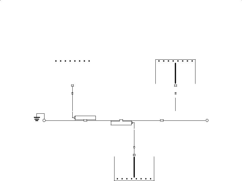
The HP Node Manager software operates under the RTE"A Operating System and accesses interface driver ID*67. This is depicted in Figure 1"2.
In addition, Figure 1"2 positions HP Node Manager software relative to other network related software operating on the system. Generally, this includes applications that utilize network services such as remote file transfer, remote virtual terminal access, or remote process communication. Application and network services software may be supplied by the user or Hewlett"Packard. (Consult your nearest Sales and Support Office for the latest availability of Hewlett"Packard networking products.)
Introduction 1%3
NETWORK SERVICES SOFTWARE FOR HP 1000 A7SERIES COMPUTERS (USER7WRITTEN OR SUPPLIED
BY HEWLETT7PACKARD)
NODE MANAGER SOFTWARE FOR CONFIGURATION, EVENT%LOGGING, STATISTICS AND DIAGNOSTICS
INTERFACE DRIVER SOFTWARE
Part of the
RTE7A Operating System
LAN INTERFACE CONTROLLER Connects Host to LAN
(Up to 8 per Host Computer)
LOCAL AREA NETWORK (LAN)
(Cable and Connecting Devices)
Figure 1%2. Node Manager Software Relationships
System Memory
Node Manager software uses approximately 85 pages (1 Kword per page) of system memory for operation. It consists primarily of three modules with approximate requirements as follows:
NM |
: 32 pages |
NM2 |
: 25 pages |
NMGR |
: 26 pages |
During system generation and installation, memory must be allocated for class numbers (refer to Chapter 3 ). Node Manager software requires two class numbers for proper operation.
1%4 Introduction
LANVCP Operation
LAN Virtual Control Panel (LANVCP) server software for downloading systems or controlling •front panel" operations of a remote node is provided with VC+ (HP 92078A). For a given LANIC card, the LANVCP server software and the Node Manager software receive packets through the same •channel", which is governed by the design of the driver and other software. An intermediate program, DISPATCH, is provided to inspect and properly route incoming packets to the appropriate program or software module. DISPATCH must be used when both the Node Manager and other LANVCP software access the same LANIC card.
The server software required for LANVCP operation are the following modules: DISPATCH, RMVCP, VCPMT, IPL_BUILD and IPL_EDIT. These modules are shipped in the /VCPLUS/LANVCP directory. LANVCP operation and these required modules are described in more detail in Chapter 6.
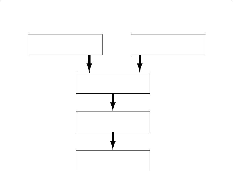
Node Manager Software Services
The Node Manager software provides four primary categories of services: Configuration, Statistics, Diagnostics and Event Logging. Since Node Manager software at one node can •talk to" Node Manager software at another node, these services may be accessed locally or remotely. This is illustrated in Figure 1"3.
End User
Terminal
User Interface
Commands From
Local User Interface
Commands |
|
|
|
|
Commands |
||
Node Management Server |
|||||||
From Remote |
|
|
|
to Remote |
|||
|
|
||||||
Server |
|
|
|
|
Server |
||
|
|
|
|
|
|
|
|
|
|
Access to |
|
|
|
||
|
|
Node Manager Services |
|
|
|
||
Configuration 
 Statistics
 Diagnostics
 Event Logging
Figure 1%3. Node Manager Software Services
Introduction 1%5

Configuration Services
Node Manager software may be used to configure a node. Configuration refers to the setting of various interface card and driver parameters that govern a node's behavior, as well as maintaining special data in software directories and files.
For example, a node may be configured into one or more modes for receiving and accepting packets from the LAN. These Packet Filter Modes (Individual, Multicast, Broadcast, and Promiscuous) are described later.
In addition, a node's Station Address and Download Server Station Address stored on the LANIC card may be temporarily or permanently altered.
Other items configurable include the node's Retry Limit, and whether or not to save and log •bad" or •trace" packets. These and others will be discussed in detail later in this manual.
Statistical Services
Node Manager software may be used to access and provide a number of useful statistics of node performance. These include, for example, •Good Bytes" transmitted, •Good Packets" transmitted, transmission errors, receiving errors, collisions, and packets discarded. In addition, the statistical counters may be reset. A complete list of statistical data available and how to retrieve it (local and remote nodes) are provided later in this manual.
Diagnostic Services
Node Manager software can be used for limited diagnostics of the local node, and of a remote node if communications to the remote Node Manager software remains intact.
For example, you can initiate an interface card self"test that checks card hardware and firmware operation. For the integrity of the connection between the interface card and LAN coaxial cable, you can initiate an External Loopback test. In addition, special IEEE 802.3 packets (TEST, and XID packets) may be transmitted to remote nodes, where they are processed and returned.
Finally, Node Manager software can check for the existence of applicable files and directories of both local and remote nodes.
Event Logging Services
On occasion, received packets cannot be delivered to an intended program (•orphan" packets), or do not meet IEEE 802.2/802.3 criteria (•bad" packets). Or, it may be desirable to track unsuccessfully transmitted packets (•trace" packets). When a node is properly configured, the Node Manager software will log key information from these packets to an Event Log file saved on disk. This information may be accessed through Node Manager software for examination and analysis. Further details of this feature are provided later.
1%6 Introduction

Implementation Considerations
Depending on a node's function, Node Manager software may be implemented at three basic levels. These are illustrated in Table 1"1.
Table 1%1. Types of Nodes
Type |
Description |
When Used |
|
|
|
Slave Node |
Disk7 or memory7based nodes that |
Minimum configuration nodes used |
|
provide Node Manager Server |
to execute7only Node Manager |
|
duties from remote nodes only. |
commands. |
Manager Node |
Preferably disk7based, but may be |
Used to manage local or remote |
|
memory7based nodes, that provide |
nodes, any of which may be slave |
|
Node Manager Server duties from a |
nodes. At least one LAN/1000 node |
|
local User Interface and from |
must be a Manager Node. |
|
remote nodes. |
|
File Server Node |
A disk7based Manager Node that |
Used to store special link data of |
|
stores and maintains special link file |
nodes being managed (including |
|
data of the local and remote nodes |
itself). Managed nodes access this |
|
(usually memory7based nodes). |
data through Node Manager soft7 |
|
|
ware. |
|
|
|
Slave nodes are those operating with the minimum number of Node Manager software modules. They are execute"only nodes, and report to another system concerning their current status. You cannot directly access Node Manager software from a Slave node because it does not contain the Node Manager User Interface modules needed. Each HP 1000 A"Series computer on the LAN should have this level of Node Manager software installed.
In Manager Nodes, all Node Manager software modules are installed. Each node on the LAN that is running Node Manager software should be accessible to a designated Manager Node. It is recommended that Manager Nodes be disk"based, but this is not required. Also, more than one node on a LAN may be designated as a Manager Node.
A File Server Node also contains all Node Manager software modules, but must be disk"based. It is used to •permanently" save certain link information of designated nodes in files on disk (Event Log, and Multicast Address list). Because of its node"to"node communication capability, Node Manager software can retrieve and update this information over the LAN.
File Server Nodes perform these services for itself, and memory"based or disk"based nodes. They allow a centralized network management approach for the collection of link data from a group of nodes. More than one node on a LAN may serve as a File Server Node when the applicable nodes are properly configured.
Introduction 1%7

Designating Nodes
Designating nodes on a LAN to one or more of the above types is application dependent. The following should be considered:
Economy |
If the network considerations dictate that a disk is not needed at a |
|
particular node, then a minimum system for execute"only capabilities may |
|
be a good choice. If this is the case, a Slave Node containing only the Node |
|
Manager software File Server module (NMGR, described later) is |
|
configured. This module requires approximately 26"pages of physical |
|
memory. |
Performance |
Software overhead and disk accesses by Node Manager software may |
|
impact node performance. Depending on the application, network accesses |
|
by Node Manager may add to network traffic, but this should be negligible. |
|
Slave Nodes might be considered for high performance, execute"only |
|
applications, and are normally configured to update or retrieve file data at |
|
a remote disk"based node over the LAN. |
|
At least one HP 1000 node on the LAN must be a Manager Node and |
|
contain all Node Manager software modules. If file storage for other nodes |
|
on the network is required, it may be a File Server node as well. |
Security |
The Node Manager software is a powerful utility with significant impact on |
|
LAN operations. Security will depend upon the user's selective |
|
configuration of Node Manager software modules operating on any |
|
particular node. The Node Manager •User Interface" modules (NM and |
|
NM2, described later) installed on a node will permit users to reconfigure |
|
the network virtually without restriction. For this reason, it is |
|
recommended that User Interface modules be configured only on nodes |
|
where the person designated as the Network Manager exercises direct |
|
control. |
High Availability |
Maximum uptime operation for the network or individual nodes may be |
|
important. Individual nodes that fail may lose their link configuration data. |
|
File Server Nodes maintaining this information on disk should be located in |
|
areas least likely to be disturbed. |
|
A distribution of File Server Nodes around the network may help to |
|
minimize the number of nodes downed by a failed File Server Node. |
|
In continuous process applications, battery backup and spare LANIC cards |
|
at Manager and File Server Nodes may be considered. |
1%8 Introduction
General Information
This section provides the foundation for understanding the underlying operation of the Node Manager software.
If you are already familiar with IEEE 802.2 and 802.3 terminology and concepts, this section may be a review. However, it also contains specific information regarding the Hewlett"Packard implementation of the standards.
Open Systems Interconnection Model
Hewlett"Packard's Local Area Networking implementation was guided by the International Standards Organization (ISO) Open Systems Interconnection (OSI) reference model. The model is based on a layered architecture that facilitates a modular approach for network communications development. The seven layers of the model are shown in Figure 2"1.
Application Layer 7
Presentation Layer 6
Session Layer 5
Transport Layer 4
Network Layer 3
Data Link Layer 2
Physical Layer 1
Figure 2%1. Layers of the OSI Model
General Information 2%1

Along with the LAN coaxial cable, the hardware provided with the HP 12076A LAN/1000 Link product and the driver satisfy the first two layers of the OSI model by conforming to the Institute of Electrical and Electronic Engineers (IEEE) standards 802.2 Type 1 and 802.3. The relationships among the HP 12076A, IEEE standards, and OSI model are shown in Figure 2"2.
. |
. |
|
|
|
|
||
. |
. |
|
|
|
|
||
|
Network Layer 3 |
|
|
|
|
|
|
|
|
|
|
|
|
|
|
|
|
|
|
|
|
|
|
|
|
|
|
|
Logical Link Control |
|
|
|
|
|
|
|
|
Driver ID*67 |
|
|
Data Link Layer 2 |
|
|
802.2 |
Type 1 and 2 Services |
|
|
|
|
|
|
|
|
Type 1 Services |
|
|
|
|
|
|
Medium Access Control |
|
|
|
|
|
|
|
|
|
|
|
|
|
|
802.3 |
|
|
LANIC Card, |
|
|
|
|
|
|
||
|
Physical Layer 1 |
|
|
Physical Signalling |
|
Cables, & LAN |
|
|
|
|
|
|
|||
|
|
|
|
|
Hardware |
||
|
|
|
|
|
|
|
|
|
|
|
|
|
|
|
|
|
|
|
|
|
|
|
|
|
OSI |
|
|
|
IEEE 802 |
|
HP 12076A |
|
MODEL |
|
|
|
Standard |
|
Implementation |
|
|
|
|
|
|
|
|
Figure 2%2. HP 12076A Relationships to Standards
Useful communications with other computer nodes, other local area networks, or other general networks may be accomplished by meeting the additional requirements of OSI layers 3 through 7. These layers may be met by software supplied by the user, third parties, and Hewlett"Packard. (Consult your nearest HP Sales and Support Office for the availability of networking software products.)
Note
Although it accesses the LANIC card driver, the HP Node Manager software should not be misconstrued as meeting or containing layers 3 through 7 of the OSI model. As a tool for performing various Network Management services on an IEEE 802.3 LAN, it does conform to a Hewlett"Packard Network Manage ment Architecture that employs a special HP Network Management Protocol.
2%2 General Information

IEEE 802 Service Types
The IEEE standards allow two types of services that can be provided to the next layer of software:
Type 1 |
designates unacknowledged connectionless service. A successfully trans" |
|
mitted packet is presumed to be received by a receiving node. There is no |
|
requirement at the physical or data link layers for the receiving node to |
|
acknowledge packet receipt. |
Type 2 |
designates connection"oriented services. A data link layer connection must |
|
be established, and there is flow control and error recovery. A sending |
|
node is guaranteed that its successfully transmitted packet was properly |
|
received by the receiving node. |
Class 1 stations support Type 1 services only, whereas Class 2 stations support Type 1 and Type 2 services at the data link layer.
Note
Hewlett"Packard's implementation at the driver and interface card level is for Class 1 stations. Type 2 services, if required, are provided in higher levels of software. For example, some HP Node Manager software transmissions require replies from remote nodes; improper or response failure result in retransmis" sion or error messages to the user.
Transmission Frames
When transmitted or received on the LAN coaxial cable medium, a bit stream that conforms to the IEEE 802.3 Standard is called a frame. Communications over the LAN is conducted through the transfer of one or more frames.
Note
In this manual, the terms •frames" and •packets" are generally used inter" changeably. Although •frame" is more aptly used in physical transmission level discussions, while •packet" applies more to data exchange in higher levels of software, the use of •packet" has grown through common usage. Note, how" ever, that a packet at one level may be quite different from a packet at another, and care should be taken to avoid confusion. It is hoped that usage here is self" evident and clear.
General Information 2%3

Format
An IEEE 802.3 packet (or more properly, Medium Access Control Frame) consists of eight (8) fields. A packet starts with a Preamble, and ends with a Frame Check Sequence. One of the fields, the Protocol Data Unit, is used to implement the Logical Link Control protocol defined by the IEEE 802.2 Standard. This is illustrated in Figure 2"3. Under the IEEE 802.2 Standard, the Protocol Data Unit field is further divided into additional fields, as illustrated in Figure 2"4.
|
|
IEEE 802.3 |
|
|
|
|
|
Last Field |
|
Logical Link |
|
|
|
|
First Field |
Transmitted |
|
Control |
|
|
|
|
Transmitted |
|
|
|
|
|
|
|
|
Frame |
Pad |
Protocol |
|
Source |
Destination |
Start of |
|
Check |
(if |
Data |
Length |
Address |
Address |
Frame |
Preamble |
Sequence |
needed) |
Unit |
|
|
|
Delimiter |
|
4 |
(0-43 |
3-1500 |
2 |
6 |
6 |
1 |
7 |
bytes |
bytes) |
bytes |
bytes |
bytes |
bytes |
byte |
bytes |
|
|
|
|
|
|
|
|
IEEE 802.3
Medium Access Control Frame
Figure 2%3. IEEE 802.3 Frame and Location of IEEE 802.2 Sublayer
|
IEEE 802.2 PROTOCOL DATA UNIT |
|
|
|||
|
|
|
|
|
|
|
|
INFORMATION |
|
SSAP |
|
DSAP |
|
|
CONTROL |
ADDRESS |
ADDRESS |
|
||
|
|
|
|
|
|
|
|
Integral number |
8 bits |
8 bits |
|
8 bits |
|
|
of Bytes |
|
|
|||
|
(Type 1) |
|
|
|
|
|
|
|
|
|
|
|
|
|
|
|
|
|
|
|
Last Byte |
|
|
|
First Byte |
||
Transmitted |
|
|
|
Transmitted |
||
Figure 2%4. IEEE 802.2 Sublayer Fields
Standard or custom communication protocols between higher layer processes are employed in the Information field of the Protocol Data Unit. For example, Node Manager software communications between a local and remote node is accomplished through a Hewlett"Packard Network Management protocol embedded in the Protocol Data Unit Information field.
Excluding the Preamble and Start Frame Delimiter, a packet must be at least 64 bytes, and can be up to 1518 bytes long.
2%4 General Information

Field Definitions
Preamble
The Preamble consists of seven (7) bytes of alternating •1s" and •0s", as shown below. It is inserted into a transmitted packet by LANIC card hardware. For received packets, the LANIC card uses the preamble for signal synchronization. The preamble is not incorporated into the Frame Check Sequence algorithm.
last bit |
first bit |
transmitted |
transmitted |
01010101 01010101 01010101 01010101 01010101 01010101 01010101
Preamble Sequence
Start Frame Delimiter
The Start Frame Delimiter is a single byte that marks the start of the frame. It is also inserted into the packet by the LANIC card hardware. It is not included in the Frame Check Sequence algorithm.
last bit transmitted |
first bit transmitted |
11010101
Start Frame Delimiter Byte
Destination Address
The Destination Address field is used to specify the node, or nodes, for which a packet is intended. For an individual node, it is the station address of the LANIC card. For a group of nodes, it is the •Multicast Address" configured in those nodes. For all IEEE 802.3 nodes on the LAN, it is the •Broadcast Address". These addresses are discussed below.
Note
The Node Manager software can be used for configuring the LANIC card's mode for receiving packets based on the packet's Destination Address. This is discussed in Chapters 4 and 5.
General Information 2%5

The Destination Address field is 48 bits (6 bytes) long, as follows: (In this manual, the Destination Address is normally expressed as a 12"digit hexadecimal number.)
msb |
|
|
|
|
|
|
lsb (transmitted first) |
||
7 |
6 |
5 |
4 |
3 |
2 |
1 |
0 |
|
|
|
|
|
|
|
|
|
|
Most Significant Byte |
|
MA |
MA |
MA |
MA |
MA |
MA |
U/L |
I/G |
||
(transmitted first) |
|||||||||
|
|
|
|
|
|
|
|
|
|
MA |
MA |
MA |
MA |
MA |
MA |
MA |
MA |
|
|
|
|
|
|
|
|
|
|
|
|
MA |
MA |
MA |
MA |
MA |
MA |
MA |
MA |
|
|
|
|
|
|
|
|
|
|
|
|
CA |
CA |
CA |
CA |
CA |
CA |
CA |
CA |
|
|
|
|
|
|
|
|
|
|
|
|
CA |
CA |
CA |
CA |
CA |
CA |
CA |
CA |
|
|
|
|
|
|
|
|
|
|
|
|
CA |
CA |
CA |
CA |
CA |
CA |
CA |
CA |
Least Significant Byte |
|
|
|
|
|
|
|
|
|
(transmitted last) |
|
where:
CA = Card Address bits comprising the lower six hex digits
MA =Manufacturer's Address bits. Note that the two least significant bits of the most significant byte have the following meanings:
U/L |
= |
0 |
Globally Administered Address |
|
= |
1 |
Locally Administered Address |
I/G |
= |
0 |
Individual node address |
|
= |
1 |
Group of nodes address |
The U/L (Universal/Local) bit determines whether the address is globally administered, or locally administered. A •globally administered address" implies a universally unique address as administered by the IEEE. When shipped from the factory, each Hewlett"Packard LANIC card contains such an address: a unique Manufacturer's Address (08 00 09 hex) assigned to Hewlett"Packard, and the lower six hex digits assigned by Hewlett"Packard. A •locally administered address" is controlled by the user, and is probably not universally unique.
The I/G bit defines the Destination Address as an individual or group address. An •individual" address is associated with a particular station on the network and implies that a single LANIC card is addressed, whereas a •group" address implies more than one station (or card) is addressed.
A group address in the Destination Address Field refers to a •Multicast" or •Broadcast" address. In addition to its individual address, each LANIC card on the LAN can be configured to accept common addresses shared by subgroups of LANIC cards. Such addresses are referred to as •Multicast" addresses; a node's Multicast Address List allows a node to be tied to several different subgroups for receiving common packets.
A •Broadcast" address is a multicast address that denotes the set of all stations on a LAN. It is predefined by the IEEE to consist of all •1s" in the Destination Address Field. By convention and
2%6 General Information

under firmware control, each LANIC card on the LAN will accept a packet that contains a Broadcast Destination Address.
An example of a Destination Address Field containing the address 08 00 09 00 02 0B (hex) is shown below. Because the first two digits are 08, it is a globally administered, individual station address (U/L and I/G bits are both •0").
msb |
|
|
|
|
|
|
lsb (transmitted first) |
|
7 |
6 |
5 |
4 |
3 |
2 |
1 |
0 |
|
|
|
|
|
|
|
|
|
|
0 |
0 |
0 |
0 |
1 |
0 |
0=U |
0=I |
08 (hexadecimal) |
|
|
|
|
|
|
|
|
|
0 |
0 |
0 |
0 |
0 |
0 |
0 |
0 |
00 |
|
|
|
|
|
|
|
|
|
0 |
0 |
0 |
0 |
1 |
0 |
0 |
1 |
09 |
|
|
|
|
|
|
|
|
|
0 |
0 |
0 |
0 |
0 |
0 |
0 |
0 |
00 |
|
|
|
|
|
|
|
|
|
0 |
0 |
0 |
0 |
0 |
0 |
1 |
0 |
02 |
|
|
|
|
|
|
|
|
|
0 |
0 |
0 |
0 |
1 |
0 |
1 |
1 |
0B |
|
|
|
|
|
|
|
|
|
Example of Destination Address Field with address 08 00 09 00 02 0B (hex)
Source Address
The Source Address field contains the Station Address of the LANIC card from which a packet is sent. It is the same length as the Destination Address field.
When the Node Manager software formats a packet for transmission, empty space is allocated for the Source Address. The LANIC card inserts the Station Address stored on the card into this space.
Length
The Length field provides the number of valid data bytes that follow in the Protocol Data Unit field. For an IEEE 802.2 and 802.3 packet, the Length field can be 1500 (decimal) bytes maximum. Note that for short data fields, the Length field should not include the invalid data inserted by the •pad" function discussed later.
General Information 2%7

Protocol Data Unit
The Protocol Data Unit field contains data to implement the IEEE 802.2 Logical Link Control protocol, and to implement higher layers of software protocol for peer"to"peer communication processes (such as Node Manager"to"Node Manager software residing on separate nodes). The number of bytes of valid data (up to 1500 bytes) is specified by the Length field. If valid data is less than 46 bytes, a Pad field is automatically added by the LANIC card to maintain minimum packet transmission size.
The Protocol Data Unit is comprised of the DSAP, SSAP, and Information fields (as defined by the IEEE 802.2 Standard). Each of these fields is described next.
Destination Service Access Point (DSAP) Address
The Logical Link Control DSAP field contains a single address that identifies one or more service access points (SAPs) to which the information field is directed. (SAP addresses generally provide the logical connections with Network Layer processes of the OSI model.) When it identifies one service access point, or Network Layer process, it is an •Individual DSAP". When it identifies multiple service access points, it is a •Group DSAP". The format of the DSAP address field is described below.
Note
Hewlett"Packard software does not support operation with packets containing a Group DSAP. For operation with Group DSAP packets, user"written routines are required. Refer to the HP 12079A LAN/1000 Link Direct Driver Access Manual product, part number 12079"90001, for additional information.
|
|
|
|
(msb) |
|
|
|
|
|
|
(lsb) |
||||
|
|
|
Last Bit |
|
|
|
|
|
First Bit |
||||||
|
|
Transmitted |
|
|
|
|
Transmitted |
||||||||
|
|
|
|
|
|
|
|
|
|
|
|
|
|
|
|
|
|
|
|
D |
|
D |
D |
D |
D |
D |
Dx |
I/G |
|
||
|
|
|
|
|
|
|
|
|
|
|
|
|
|
|
|
|
|
|
|
|
|
|
|
DSAP Address Field |
|
|
|
|
|||
where: |
|
|
|
|
|
|
|
|
|
|
|
|
|
|
|
D |
represents a DSAP address bit. |
|
|
|
|
|
|
|
|||||||
Dx |
0 indicates the DSAP is locally administered (user"defined) |
||||||||||||||
|
1 indicates it is administered by the IEEE (see below) |
||||||||||||||
I/G |
is an Individual/Group type designation bit indicating whether the packet data is |
||||||||||||||
|
directed to an individual DSAP or a Group DSAP, as follows: |
||||||||||||||
|
I/G |
= 0 |
|
Individual DSAP, intended for a single process |
|||||||||||
|
I/G |
= 1 |
|
Group DSAP, intended for more than one process |
|||||||||||
2%8 General Information

A legal (user"defined) DSAP address takes the following form (note the •0" in the second bit):
|
(msb) |
|
(lsb) |
||||||||
Last Bit |
First Bit |
||||||||||
Transmitted |
Transmitted |
||||||||||
|
|
|
|
|
|
|
|
|
|
|
|
|
D |
D |
D |
D |
D |
D |
0 |
I/G |
|
||
|
|
|
|
|
|
|
|
|
|
|
|
Legal DSAP Address
Certain DSAPs are defined by the IEEE 802.2 Standard for reserved use, that is, they are administered by the IEEE. They are of the following form (note the •1" in the second bit):
|
(msb) |
|
(lsb) |
||||||||
Last Bit |
First Bit |
||||||||||
Transmitted |
Transmitted |
||||||||||
|
|
|
|
|
|
|
|
|
|
|
|
|
D |
D |
D |
D |
D |
D |
1 |
I/G |
|
||
|
|
|
|
|
|
|
|
|
|
|
|
Reserved DSAP Address for IEEE 802 Definition
For example, the IEEE administers the following DSAP values as follows:
DSAP Value |
|
Description |
|
FF (hex) |
|
Global DSAP, consisting of the I/G bit set to •1", and the seven DSAP |
|
|
|
address bits set to •1". The Global DSAP designates the group of all active |
|
|
|
DSAPs to receive the packet data. |
|
02 (hex) |
|
DSAP for individual Logical Link Control management functions (as |
|
|
|
defined by the IEEE), consisting of the I/G bit set to •0", and the seven |
|
|
|
DSAP address bits set to •0000001". (Do not associate this DSAP with the |
|
|
|
Hewlett"Packard Node Manager software.) |
|
03 (hex) |
|
DSAP for group Logical Link Control management functions, consisting of |
|
|
the I/G bit set to •1", and the seven DSAP address bits set to •0000001". |
||
06 (hex) |
DSAP for Internet Protocol (IP), based upon a Defense Advanced |
||
|
Research Projects Agency (DARPA) standard for an internetwork protocol. |
||
|
The I/G bit is set to •0", and the seven DSAP address bits are set to |
||
|
•0000011". (Note: HP networking software uses IP and therefore requires |
||
|
|
the use of this DSAP. This is in addition to HP reserved SAPs described |
|
|
|
below.) |
|
A special predefined value is the •Null" DSAP. The Null address neither identifies a Network Layer process nor management function. Instead, it addresses the Medium Access Control sublayer, which in this case is the LANIC card and firmware.
00 (hex) |
Null DSAP, consisting of the I/G bit set to •0" and the seven DSAP address |
|
bits set to •0". With the HP 12076A implementation, the card firmware |
|
detects a Null DSAP in incoming XID or TEST packets (defined later) and |
|
responds appropriately. The driver and upper level software are not |
|
accessed. |
General Information 2%9

Hewlett"Packard reserves certain SAPs for operation of HP software. They are:
F0 (hex): |
(reserved) |
F4 (hex): |
HP Link Level LAN Diagnostic Software DSAP |
F8 (hex): |
HP Network and Node Manager Software DSAP |
|
(also may be used for remote VCP and FCL) |
FC (hex): |
HP Network Services DSAP for PROBE protocol |
Source Service Access Point (SSAP) Address
The Logical Link Control SSAP field contains a single address that identifies a service access point (SAP) from which the information field is sent. (Note that Group SSAPs are not defined.) The format of the SSAP address field is as follows:
|
|
(msb) |
|
|
|
|
|
|
|
(lsb) |
||||
|
Last Bit |
|
|
|
|
|
|
|
First Bit |
|||||
|
Transmitted |
|
|
|
|
|
Transmitted |
|||||||
|
|
|
|
|
|
|
|
|
|
|
|
|
|
|
|
|
S |
|
S |
S |
S |
|
S |
S |
Sx |
C/R |
|
||
|
|
|
|
|
|
|
|
|
|
|
|
|
|
|
|
|
|
|
|
|
SSAP Address Field |
|
|
|
|
||||
where: |
|
|
|
|
|
|
|
|
|
|
|
|
|
|
S |
indicates SSAP address bits |
|
|
|
|
|
|
|||||||
Sx |
0 indicates the SSAP is locally administered (user"defined) |
|||||||||||||
|
1 indicates it is administered by the IEEE (see below) |
|||||||||||||
C/R |
is a Command/Response bit indicating whether the packet data from this |
|||||||||||||
|
SSAP is an initial outgoing command, or a response resulting from some |
|||||||||||||
|
previous incoming command, as follows: |
|||||||||||||
C/R = 0 Packet data is a command from this SSAP
C/R = 1 Packet data is a response from this SSAP
A legal (user"defined) SSAP address takes the following form (note the •0" in the second bit):
|
(msb) |
|
|
|
|
|
|
(lsb) |
||||
Last Bit |
|
|
|
|
|
First Bit |
||||||
Transmitted |
|
|
|
|
Transmitted |
|||||||
|
|
|
|
|
|
|
|
|
|
|
|
|
|
S |
|
S |
S |
S |
S |
S |
0 |
C/R |
|
||
|
|
|
|
|
|
|
|
|
|
|
|
|
|
|
|
|
|
Legal SSAP Address |
|
|
|
|
|||
2%10 General Information
 Loading...