


INSTRUCTIONS FOR INSTALLATION & USE
WD63, WD64
Hotpoint recommends, for your own safety and to ensure you get the best possible results from your Washer Dryer, you read through this booklet and follow these steps thoroughly.
STEP 1 Electrical Guide
Choose a location for your washer dryer, where possible on a solid floor, with the electrical sockets and water supply taps easily accessible.
Allow sufficient space: 600mm width, 600m depth and 900mm height.
DO NOT install in a bath or shower room.
WARNING: This appliance must be earthed.
STEP 3 Dispenser Drawer
Read through this section to familiarise yourself with the different compartments within the dispenser drawer.
Hotpoint recommend the Persil range of detergent products.
NOTE: Always follow manufacturer’s dosage recommendations.
STEP 2 Installation Guide
packaging material in a safe remove any labels.
through thoroughly to understand each stage begin.
may be charged for a service call if a washer dryer is caused by
or misuse.
STEP 4 Wash Guide
A wash chart is provided to help you to select your required programme.
Examples given for the maximum washing load weight for different fabric types.
STEP 5 Options Guide
All available optional wash features are explained within this section - These allow you to adjust your selected wash programme to suit your needs.
NOTE: In addition to the temperature of the incoming water, the selection of optional wash features will affect the programme times.
STEP 6 Drying Guide
A guide to drying times is provided for independent drying programmes, along with a list of items not suitable for tumble drying.
Examples given for the maximum drying load weight for different fabric types.
NOTE: Always make sure the mains button is in the OFF position before selecting an independent drying programme.
STEP 7 Wash & Auto Dry Programme
explanation
DO
NOTE: Hotpoint recommend, on completion of your programme, that you switch off both the electricity and water supply to the appliance.
STEP 8
READ BEFORE CONTACTING SERVICE!
Troubleshooting
Please refer to the Troubleshooting section if you have any problems when using your washer dryer.
There may be nothing wrong!
Read the rest of these instructions to get the best from your appliance, remember to fill in your guarantee registration.
Keep these instructions in a safe place for quick reference.
STEP 1 |
Electricity Supply |
WARNING: The appliance must be earthed.
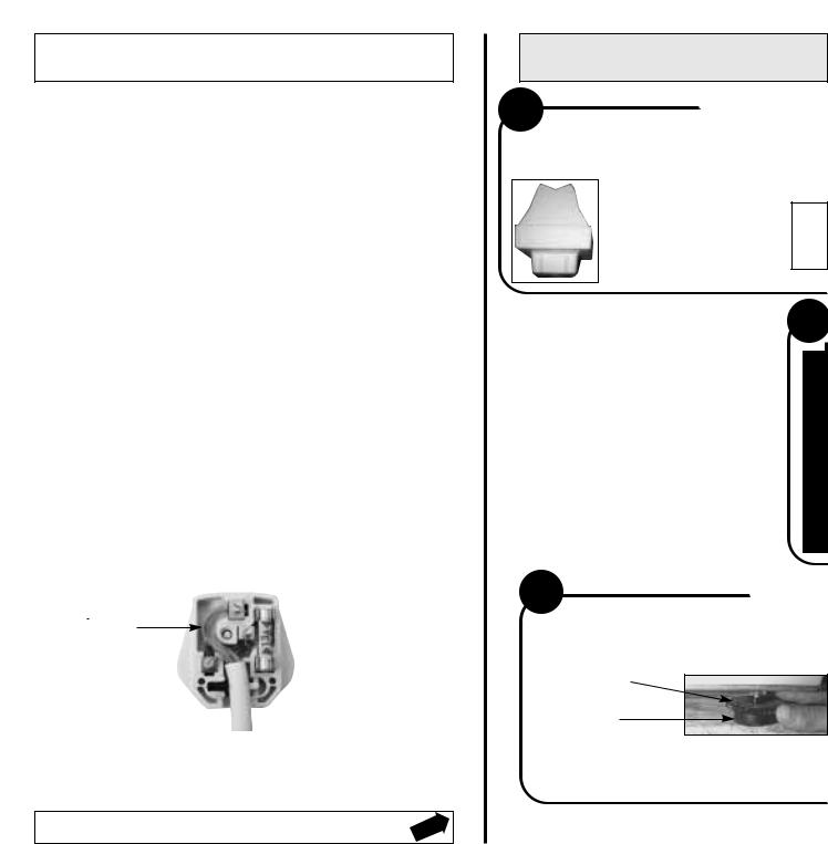
Fuses
Your appliance comes fitted with a plug and a 13A fuse. If you need to replace the fuse, only those rated at 13A and ASTA approved to BS1362 should be used. To change fuse lift holder to vertical position and lift fuse out. To replace, insert fuse and push fuse holder down into locked position. Correct replacement is identified by colour coding or the marking on base of plug.
WARNING: Do not use plug unless fuse holder is in locked position.
Changing the Mains Lead
A special lead can be ordered from Hotpoint Service
UK: 08709 066 066 or Republic of Ireland: 1850 302 200 If you have damaged the existing lead or require a longer one a charge will be made. It is strongly advised that this work is carried out by a qualified electrician.
Changing the Plug
Cut off and dispose of the supplied plug if it does not fit your socket.
WARNING: To avoid a shock hazard do not insert the discarded plug into a socket anywhere else.
IMPORTANT: WIRES IN THE MAINS LEAD ARE COLOURED IN ACCORDANCE WITH THE FOLLOWING CODE:
Green/Yellow |
- |
Earth |
Blue |
- |
Neutral |
Brown |
- |
Live |
If you change the plug, the colour of wires in the mains lead may not correspond with the colour of the markings identifying terminals in the plug. You should therefore wire it as shown:
Green and yellow (Earth) wire to terminal marked ‘E’, symbol  , or coloured
green and yellow.
Blue (Neutral) wire to  terminal marked ‘N’ or
coloured black.
13A ASTA approved fuse to BS1362.
 Brown (Live) wire to terminal marked ‘L’ or coloured red.
CE marking certifies that this appliance conforms to the following EEC directives:
Low Voltage Equipment - 72/23/EEC & 93/68/EEC
Electromagnetic Compatibility - 89/336/EEC, 92/31/EEC & 93/68/EEC
STEP 2
1 POLYSTYRENE BLOCK...
NOTE: YOU MAY NEED A SECOND PERSON TO HELP Y RAISE AND LOWER THE APPLIANCE.
This is part of the packaging and should have come away with the polystyrene base -
IF IT HAS NOT... REMOVE IT!
4
NOT
MO
AL
W
Y
H
LEV D
(*s
5
LEVEL?...
YOUR MACHINE WILL BE NOISY IF THE TW NOT ADJUSTED SO THE MACHINE STANDS
Each foot has two parts: The Locking Dis
Locking |
Disk |
Foot |
i |
Release the locking disk on the |
ii Turn |
|
two front feet and screw the feet |
on th |
|
in or out until the machine stands |
each |
|
firm and level. |
of th |
|
|
|
|
|
|
Installation
OU
DRAINAGE
E: ALTHOUGH YOU VE THE HOOKED ONG THE GREY
DO NOT
HICHEVER
OU USE, MAKE OOKED END
EL TO, OR ABOVE RAINAGE HOSE ee Getting to Know
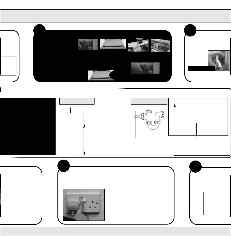
2 REMOVE TRANSIT BRACKETS...
IMPORTANT:
Internal transit brackets are fitted to prevent damage during transit and MUST be removed before use...
Failure to do so may cause damage to your machine!
|
|
|
Remove and |
|
From the rear of the |
|
machine, grip sides of |
|
retain 3 screws |
|
|
|
the worktop lid, lift, slide |
|
from the back of |
|
|
|
and pull towards you. |
|
the worktop lid |
|
|
|
|
Slide and push worktop lid back into position, ensuring front edge is correctly located into the console.
|
|
|
|
|
Remove 4 screws |
|
Remove 3 screws |
||
and the rear transit |
|
and front transit |
||
bracket - retain. |
|
bracket - retain. |
||
|
|
|
|
|
|
|
|
|
|
Replace the work top lid using the 3 original screws.
... we recommend one of the following:
3 CONNECT TO T
PLEASE USE THE NEW HOSES SUPPLIED, FITTED TO THE MACHINE.
DO NOT REMOVE!
Old hoses may cause leaks due to worn out washers.
STANDPIPE METHOD |
UNDER SINK METHOD |
TO
Hooked End Support
HOSE, |
|
|
Insert drainage hose |
|
|
|
|||
|
|
approximately 100mm |
|
|
|
|
|
|
|
|
|
|
into the standpipe. |
OR |
|
............................. |
|||
|
|
|
|
|
THE |
|
|
Standpipe height: |
|
|
|
|
|
|
|
|
|
minimum 500mm |
|
|
|
|
from the floor. |
|
|
|
|
|
|
|
|
|
|
|
cut off the blocked end of the under sink drainage unit.
800mm from floor
Fix the hooked |
Attach the GREY |
end support at |
drainage hose to the |
a minimum |
under sink drainage |
800mm from |
securely, using a |
the floor. |
clip. |
O FRONT FEET ARE FIRM AND LEVEL.
k and The Foot
ONLY the locking disk e two front feet until is up against the base e machine.
6
CONNECT TO THE POWER SUPPLY...
PLUG YOUR MACHINE INTO AN ELECTRICAL SOCKET WHICH IS EASILY ACCESSIBLE. SWITCH ON
NOTE: Hotpoint recommend extension leads are not used.
Move your machine into position, take care not to trap or kink the hoses.
TO CHECK ALL PARTS CLEAN THE INSIDE OF
SELECT A 95˚ WHITE
WIT
THIS WILL TAKE A

HE WATER SUPPLY...
i Check both hot and cold water supplies are running freely...
ii Connect fill hoses to water supply taps:
-Red or Grey Hose end to Hot
-Blue Hose end to Cold
TURN ON BOTH TAPS
If you have no hot water
supply...
A cold fill adaptor is available from your local Hotpoint authorised Service Centre or by
calling the Genuine Parts & Accessories Hotline (see KEY CONTACTS).
OF THE INSTALLATION AND TO THOROUGHLY YOUR MACHINE:
COTTON WASH PROGRAMME (refer to STEP 4)
HOUT ANY LAUNDRY |
|
and |
|
WITHOUT ANY DETERGENT |
PPROXIMATELY 2hrs 30mins TO COMPLETE
STEP 3 The Dispenser Drawer
Changing the Main
Wash Indicator:
The main wash indicator has been fitted to dispense powder detergent only.
If you wish to use liquid detergent, reposition the main wash indicator as shown below:
1 Pull the drawer out until it reaches its stop.
2 Press down on button, to release the drawer latch and remove the drawer.
3 Lift the main wash indicator out of slots, rotate and reposition for Liquid, ensuring it is secure.
4 Relocate the drawer and push back into place.
1 |
2 |
3 |
4 |
5 |
6 |
Index: |
1. Drawer latch
2. Button
3. Main wash indicator
4. Main wash compartment
5. Prewash compartment
6. Fabric conditioner compartment
Dispensing Powder
Detergent
To achieve optimum wash results we recommend that you use the detergent manufacturers dispensing cup, to dispense no more than 300ml of powder.
Dispensing Fabric
Conditioner
Pour fabric conditioner into the compartment.
We recommend that you do not exceed the maximum level indicated.
Cleaning the Dispenser Drawer &
Compartments:
It is advisable to clean the dispenser drawer regularly:
Remove the drawer, see ‘Changing the Main Wash Indicator’, wash the dispenser drawer and clean out the compartment.
Dry thoroughly and relocate.
 Loading...