


Y8150 Fresh Air Ventilation System,
W8150 Fresh Air Ventilation Control
PRODUCT DATA
FEATURES
APPLICATION
The Y8150 Fresh Air Ventilation System, W8150 Fresh Air Ventilation Control provide fresh air to a home. The control operates a fresh air intake damper and, when necessary, activates the main HVAC blower to efficiently meet ASHRAE ventilation rates.
•Designed to help meet local ventilation codes and standards, including ASHRAE 62.2-2010 standard, “Ventilation and Acceptable Indoor Air Quality in Low-Rise Residential Buildings.”
•Microcontroller optimizes the air delivery schedule to make efficient use of normal HVAC run times.
•Easy-to-use input dials allow customized ventilation for each installation.
•Test mode that includes immediate feedback to installer to confirm that air delivery requirements of selected ventilation standard are being met.
•Economical supply-only ventilation; works with forced air system.
•Can be used with other equipment, such as an HRV/ ERV, for balanced ventilation.
IMPORTANT
Please read these instructions and keep them in your records.
Put Bar Code Here
68-0282-07

Y8150 FRESH AIR VENTILATION SYSTEM, W8150 FRESH AIR VENTILATION CONTROL
SPECIFICATIONS
Y8150 includes:
W8150A Fresh Air Ventilation Control.
EARD6 Fresh Air Damper.
AT120B Transformer.
Mounting hardware for control.
Homeowner information label.
W8150 includes:
W8150 Fresh Air Ventilation Control.
Mounting hardware for control.
Homeowner information label.
Control (W8150A):
Power Supply: 20-30 Vac, 60 Hz. Power Consumption: 3.5 VA at 24 Vac.
Thermostat Fan Load: 10 mA resistive at 24 Vac. Thermostat Heat Load: 10 mA resistive at 24 Vac. Remote Terminals: 10 mA resistive at 24 Vac.
Relay Contacts:
Fan: 1.5A full load, 7.5A locked rotor at 24 Vac. Damper: 0.6A inductive, 3.1A locked rotor at 24 Vac. Auxiliary: 0.5A inductive, 2.5A locked rotor at 24 Vac.
Damper (EARD6): 24 Vac, 12 VA, 60 Hz.
Operation: Power-open, spring-closed.
Diameter: 6 in.
Transformer (AT120):
Input: 120 Vac.
Output: 27 Vac open circuit, 24 Vac full load at 20 VA. Mounting: Foot mounted.
Temperature: -20 °F to 160 °F (-29 °C to 71 °C).
Humidity: 5 to 90% RH, noncondensing.
Input Setting Ranges:
Bedrooms: 2-5.
Area: 1000-4600 sq ft.
Vent Airflow: 40-160 cfm.
Composite Setting Resolution: +/- 12% of ASHRAE 62.2-2010, recommended ventilation for single-system setup.
AT120B Approvals: UL Component Recognized: Class 2,
File No. 14881.
Location: Device can be installed in unconditioned space. Multiple devices can be installed when operating multiple HVAC systems.
Dimensions: See device dimension diagrams.
4-3/16 (106) |
1-1/4 |
|
(32) |
5-3/4
(146)
M19988A
W8150A Ventilation Control dimensions in in. (mm).
 3-1/2 (89)

3-3/8
(86)
 1-1/2
1-1/2  (38)
(38)
6
(152)
8 (203)
M19989
EARD6 Fresh Air Damper dimensions in in. (mm).
2-13/16 (71) |
3/16 |
|
|
|
(5) |
|
|
|
|
|
1-3/4 |
|
15/16 |
1 |
(44) |
|
(24) |
(25) |
|
3/16 |
|
|
|
(5) |
|
|
|
1-7/8 (48) |
|
|
|
|
|
1-5/8 |
|
|
|
(41) |
|
|
1/16 (2) |
|
|
|
M22022 |
|
|
AT120B Transformer dimensions in in. (mm).
68-0282—07 |
2 |
Y8150 FRESH AIR VENTILATION SYSTEM, W8150 FRESH AIR VENTILATION CONTROL
1 |
GF |
|
XFMR |
20 |
2 |
RC |
|
R |
|
|
|
|
||
3 |
CC |
|
C |
19 |
|
DAMPER |
|
||
4 |
CH |
|
18 |
|
|
|
|||
5 |
W |
|
AUX |
|
6 |
GT |
|
17 |
|
|
|
|||
7 |
|
|
REMOTE |
|
8 |
|
|
16 |
|
|
|
|
||
9 |
|
ON |
|
15 |
|
|
|
|
|
10 |
|
|
|
|
11 |
|
|
|
14 |
12 |
BEDROOMS |
AREA (SQFT) |
VENT AIRFLOW (CFM) |
|
|
13 |
|
|
M19990 |
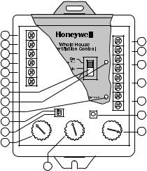
W8150 QUICK GUIDE
No. |
Name |
Description |
Function |
1 |
GF |
Equipment fan |
Allows W8150 to pass thermostat calls and, when necessary, turn on |
|
|
|
system fan for ventilation. This should be the only connection to G on the |
|
|
|
HVAC equipment. |
2 |
RC |
24 Vac cooling system |
Provides power to GF terminal to operate system fan, when necessary. |
|
|
power |
|
3 |
CC |
24 Vac cooling system |
Allows W8150 to monitor when system fan is energized. |
|
|
common |
|
4 |
CH |
24 Vac heating system |
Allows W8150 to monitor thermostat heat calls when W is energized. |
|
|
common |
|
5 |
W |
Heating |
Allows W8150 to monitor when heating is energized. |
|
|
|
|
6 |
GT |
Thermostat (or other |
Allows W8150 to monitor when GT is energized. All external equipment that |
|
|
control) fan terminal |
controls the system fan should be wired to this terminal. |
7 |
Switch |
On (optimal ventilation) |
On (optimal ventilation) – W8150 ventilates, based on control settings. |
|
|
Override |
Override – W8150 runs ventilation continuously. |
|
|
Off (Remote Only) |
Off (Remote Only) – W8150 supplies ventilation only when there is a |
|
|
|
remote call. |
8 |
Light |
Green |
Indicates device is powered and operating normally. Used in Test Mode to |
|
|
|
signal if dial settings meet chosen standard. |
9 |
Light |
Red |
Indicates the device is not operating normally. Used in Test Mode to signal |
|
|
|
if dial settings do not meet chosen standard. |
10 |
DIP1 |
Ventilation limit |
Choose between 60% (default) and 100% maximum fan run time allowed |
|
|
|
by W8150 for ventilation. |
11 |
DIP2 |
Ventilation standard |
Choose between ASHRAE 62.2 (default) and 62-1999 ventilation |
|
|
|
standards. |
12 |
BEDROOMS |
Number of bedrooms |
Used to calculate amount of ventilation necessary. |
|
|
|
|
13 |
AREA |
Square footage of |
Used to calculate amount of ventilation necessary. |
|
(SQ FT) |
conditioned space |
|
14 |
VENT |
Air delivery rate through |
Used to calculate amount of ventilation necessary. |
|
AIRFLOW |
fresh air duct. |
|
|
(CFM) |
|
|
15 |
Test |
Test button |
W8150 checks dial and switch settings, activates ventilation for up to three |
|
|
|
minutes and provides feedback to validate if chosen standard can be met. |
3 |
68-0282—07 |
Y8150 FRESH AIR VENTILATION SYSTEM, W8150 FRESH AIR VENTILATION CONTROL
No. |
Name |
Description |
Function |
16 |
REMOTE |
Remote switch (two |
24 Vac powered contacts allow a remote switch closure to call for |
|
|
terminals) |
ventilation. |
17 |
AUX |
Auxiliary (two terminals) |
24 Vac dry contacts allow W8150 to control an auxiliary device, such as |
|
|
|
exhaust fan or HRV/ERV, with a call for ventilation. |
18 |
DAMPER |
Damper (two terminals) |
24 Vac powered contacts control fresh air damper. |
|
|
|
|
19 |
XFMR C |
24 Vac ventilation control |
Supplies power to W8150 and damper from transformer provided. |
|
|
common |
|
20 |
XFMR R |
24 Vac ventilation control |
Supplies power to W8150 and damper from transformer provided. |
|
|
power |
|
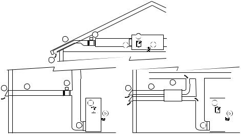
INSTALLATION
A fresh air duct and damper must be installed between the outdoors and the return side of the HVAC equipment. The W8150 control will be mounted near the HVAC system and wired between the thermostat and the fan control.
You will need…
•W8150 Fresh Air Ventilation Control.
•damper.
•transformer.
•insulated ductwork.
•outdoor weather hood.
•starting collar.
•access to 120 Vac power.
•airflow measuring tool.
TIPS:
•To meet ASHRAE 62.2-2010, system must have at least a MERV 6 filter installed.
•In cold climates, balanced ventilation is recommended. An exhaust fan or heat recovery ventilator can be used.
•Humid climates may require additional dehumidification equipment.
Choosing a location…
When choosing locations for equipment, duct connections, and fresh air intake, be sure to consult local code requirements.
Device |
|
|
Number |
Component |
Location |
1 |
Fresh air intake |
Install away from known sources |
|
|
of pollutants such as auto |
|
|
exhaust, dryer vent exhaust or |
|
|
chimney smoke. |
2 |
Fresh air duct |
Install between weather hood and |
|
|
upstream of equipment filter and |
|
|
downstream of any duct-mounted |
|
|
sensor. |
3 |
Damper |
Install damper in fresh air duct, |
|
|
where convenient. Optionally, |
|
|
install heat recovery ventilator. |
4 |
Control |
Locate the control for convenient |
|
|
access and for easy wire routing. |
5 |
Transformer |
Locate where convenient for line |
|
|
voltage connection. |
6 |
Filter |
Locate filter downstream of fresh |
|
|
air intake. |
|
|
|
TYPICAL ATTIC |
|
|
|
|
INSTALLATION |
|
|
|
3 |
4 |
|
|
|
2 |
|
|
|
|
|
|
|
|
|
6 |
5 |
|
|
1 |
|
|
|
|
|
3 |
|
3 |
1 |
2 |
1 |
2 |
HRV/ERV |
|
|
4 |
|
4 |
|
TYPICAL BASEMENT |
|
TYPICAL HRV/ERV |
|
|
INSTALLATION |
|
INSTALLATION |
|
|
|
6 |
|
6 |
M19993
68-0282—07 |
4 |
 Loading...