


ERV/HRV Ventilation Systems
PROFESSIONAL INSTALLATION GUIDE.
GUIDE D’INSTALLATION PROFESSIONNELLE.
 INCLUDED IN THIS BOX
A1 |
A2 |
B |
C |
|
|
G1 |
G2 |
G3 |
D |
E |
F |
|
|
ERV/HRV Ventilation Systems |
|
|
|
|
|
PROFESSIONAL INSTALLATION GUIDE. |
|
|
|
|
GUIDE D’INSTALLATION PROFESSIONNELLE. |
|
|
|
INCLUDED IN THIS BOX |
|
|
|
|
|
|
G4 |
G5 |
G6 |
|
OPTIONAL CONTROLS SOLD SEPARATELY |
|
|
|
Tools required to install ERV/HRV |
ERV/HRV VNT5150H1000 or VNT5150E1000 or |
|
|
|
Aluminum foil tape (UL181B) |
ERV/HRV VNT5200H1000 or VNT5200E1000 |
|
|
|
Standard screwdriver |
Heat/Energy Recovery Core (1) |
|
|
|
Crescent wrench |
|
|
|
|
Hex driver (1/4 in.) |
Filter (2) |
|
|
|
Accessories (not included) |
Professional Installation Guide |
|
|
|
6 in. diameter insulated duct |
Duct Collars (4) |
|
|
|
6 in. diameter duct |
Installation Kit |
|
|
|
Two 6 in. diameter weather hoods |
Optional Controls: 1- Vision Pro IAQ, 2 - True IAQ, |
|
|
|
|
3 - Dehumidistat H8908D, 4 - Prestige IAQ, |
|
|
|
|
5 - 20/40/60 Minute Boost Control, and |
|
|
|
|
6 - W8150 Ventilation Control |
|
|
|
|
|
OPTIONAL CONTROLS SOLD SEPARATELY |
||
Tools required to install ERV/HRV
 Aluminum foil tape (UL181B)
 Standard screwdriver
 Crescent wrench
 Hex driver (1/4 in.)
Accessories (not included)
 6 in. diameter insulated duct
 6 in. diameter duct
 Two 6 in. diameter weather hoods
A1 ERV/HRV VNT5150H1000 or VNT5150E1000 or A2 ERV/HRV VNT5200H1000 or VNT5200E1000 B Heat/Energy Recovery Core (1)
CFilter (2)
D Professional Installation Guide
E Duct Collars (4)
FInstallation Kit
GOptional Controls: 1- Vision Pro IAQ, 2 - True IAQ, 3 - Dehumidistat H8908D, 4 - Prestige IAQ,
5 - 20/40/60 Minute Boost Control, and
6 - W8150 Ventilation Control
69-2480EF-01

Installation Checklist
Included in This Box
A1 ERV/HRV VNT5150H1000 or VNT5150E1000 or
A2 ERV/HRV VNT5200H1000 or VNT5200E1000 B Heat/Energy Recovery Core
C Filter (2)
D Installation Guide
E Duct Collars (4)
FInstallation Kit
Control Options (Sold separately)
G1 - Vision Pro IAQ
G2 - True IAQ
G3 - Dehumidistat H8908D
G4 - Prestige IAQ
G5 - 20/40/60 Minute Boost Control
G6 - W8150 Ventilation Control
Tools Required (Not Supplied)
•Aluminum foil tape (UL1818)
•Standard screwdriver
•Crescent wrench
•Hex driver (1/4 in.)
Accessories (not included)
•6 in. diameter insulated duct
•6 in. diameter duct
•Two 6 in. diameter weather hoods
Warning: Installation must be performed by a qualified service technician and must comply with local codes.
Remove power to the device before installing or servicing the device.
Failure to connect the device according to these instructions may result in damage to the
device or the controls.
Liste de vérification pour l’installation
Contenu
A1 VRÉ/VRC VNT5150H1000 ou VNT5150E1000 ou
A2 VRÉ/VRC VNT5200H1000 ou VNT5200E1000 B Noyau de récupération de chaleur et d’énergie C Filtre (2)
D Guide d’installation
E Raccords de conduit (4)
FTrousse de quincaillerie
Commandes en option (vendues séparément)
G1 - Vision Pro IAQ
G2 - True IAQ
G3 - Déshumidistat H8908D
G4 - Prestige IAQ
G5 - Minuteur de ventilation à haute vitesse (20, 40 ou 60 minutes)
G6 - Régulateur de ventilation W8150
Outils nécessaires (non fournis)
•Ruban d’aluminium (UL1818)
•Tournevis standard
•Clé à molette
•Tournevis à tête hexagonale (1/4 po)
Accessoires (non inclus)
•Conduit isolé de 6 po de diamètre
•Conduit de 6 po de diamètre
•Deux hottes anti-intempéries de 6 po
Avertissement : L’installation doit être effectuée par un technicien qualifié et être conforme aux règlements locaux.
Débranchez l’appareil avant de l’installer ou d’en effectuer l’entretien.
Un branchement de l’appareil non conforme aux présentes instructions pourrait entraîner des dommages à l’appareil lui-même ou aux
commandes.
INSTALLATION INSTRUCTIONS |
INSTRUCTIONS POUR L’INSTALLATION COMMEN- |
|
BEGIN ON PAGE 1 |
||
CENT À LA PAGE 33 |
||
|

ERV/HRV Ventilation System
ABOUT YOUR NEW VENTILATION SYSTEM |
|
Benefits....................................................................... |
2 |
Determining Your Ventilation Needs........................... |
3 |
Specifications.............................................................. |
4 |
External Control Options............................................ |
9 |
INSTALLATION |
|
Install to Fit Your Application.................................... |
10 |
Installation Steps...................................................... |
13 |
Automatic Defrost..................................................... |
18 |
Wiring......................................................................... |
18 |
Prestige™ 2-wire IAQ and RF EIM Wiring......... |
19 |
Prestige™ Thermostat Wiring............................ |
20 |
VisionPRO IAQ Wiring.......................................... |
20 |
General Ventilator Wiring.................................... |
21 |
Standard Furnace Interlock Wiring with |
|
Forced Air System............................................... |
21 |
Alternate Interlock Wiring with |
|
Forced Air System............................................... |
22 |
TrueIAQ (DG115EZIQ) Wiring............................... |
22 |
INSTALLATION (continued) |
|
Dehumidistat Wiring............................................ |
23 |
W8150 Ventilation Control Wiring........................ |
23 |
Honeywell 20/40/60 Minute Boost Control |
|
Timer..................................................................... |
23 |
Control Panel............................................................. |
24 |
Balancing Steps........................................................ |
25 |
Balancing Reset................................................... |
26 |
Checkout................................................................... |
26 |
MAINTENANCE |
|
Periodic Maintenance............................................... |
27 |
Cleaning..................................................................... |
28 |
Troubleshooting........................................................ |
29 |
Parts List................................................................... |
30 |
WARRANTY |
|
5-Year Limited Warranty........................................... |
32 |
•Prior to installing, serious consideration must be taken to ensure this ventilation system will operate properly if integrated to any other type of mechanical system, i.e. a forced air system, or an air handling unit. To ensure proper operation and compatibility of both systems, it is required that the unit’s airflows (intake and exhaust) be balanced, by following the procedures found in this manual
•Install the unit with space to access the front panel controls and the side access panel for maintenance and service.
•To ensure quiet operation, do not place the device directly on the structural supports of the home.
•The product is for residential applications only. Must be installed in accordance with all national and local regulations, building and safety codes
?NEED HELP? For assistance with this product please visit http://yourhome.honeywell.com or call Honeywell Customer Care toll-free at 1-800-468-1502.
Read and save these instructions.
® U.S. Registered Trademark. Patents pending. Copyright © 2010 Honeywell International Inc. All rights reserved.
ERV/HRV Ventilation Systems 69-2480EF—01

About the ERV/HRV Ventilation System
The Honeywell ERV/HRV Ventilation System provides improved indoor air quality through its high performance and efficiency.
Benefits
•Ventilation with sensible heat recovery (ERV and HRV)
•Ventilation with latent heat recovery (ERV only)
•Simplified mounting (hanging)
•Removable duct collars for easy ducting to the unit
•Intuitive balancing via two variable speed motors and a speed control
CAUTION: Electrical shock and fire hazard. Can cause personal and equipment damage.
•Before servicing or cleaning the system, always remove the power cord from the AC wall outlet.
•Wear protective clothing and safety glasses when installing ventilator and working with sheet metal.
•To reduce the hazards of electric shock or fire, do not perform any service to the system other than those stated in the operating manual instructions.
•To reduce the risk of electric shock, this ventilation system comes equipped with a 3-prong plug-in. This plug will fit in a polarized outlet only one way.
•Do not use ventilation system for outdoor application.
•Do not pull or twist power cord when disconnecting it from the ventilation system. Grasp the plug firmly, not the cord.
•Do not modify the power plug in any way; if modified, risk of electric shock, fire, or even damage to the unit may occur.
•Do not use the ventilation system for removal of flammable fumes, gases or connect directly to any appliances.
•Use a 120 VAC outlet only.
•Do not use an extension cord.
•Do not obstruct or cover the air intake or air outlet of the ventilation system.
•Do not modify, repair or disassemble this system. These tasks are to be performed by authorized serviced personnel only. Fire, electrical shock and/or bodily injury may occur if these warnings are not followed.
•To prevent injuries, do not operate the ventilation system, while servicing or maintaining. There are impeller wheels turning at a very high speed that must fully stop rotating prior to accessing the inside of the unit.
•Always assess how the operation of the ventilation system may interact with vented combustion equipment (i.e. Gas Furnace, Oil Furnace, Combustion, Appliances, etc.)
•Ensure unit is properly installed and suspended to prevent falling or dropping injuries.
2 |
ERV/HRV Ventilation Systems 69-2480EF—01 |

Determining Your Ventilation Needs
How much fresh air do you need?
Good air quality is based in part on the capacity of the home’s ventilation system. Usually, the unit’s capacity is measured in CFM (Cubic Feet per Minute) or L/s (Liters per second) of fresh air being distributed in the living space. Use the ASHRAE 62.2 Ventilation Standard, the Room Count Calculation Method, or the Air Change Per Hour (ACH) Method to determine your ventilation needs.
ASHRAE 62.2 Ventilation Standard
ASHRAE 62.2 CFM Sizing Chart
Floor Area (ft2) |
Number of Bedrooms / CFM |
|
|
|
||
|
|
|
|
|
||
0-1 |
2-3 |
4-5 |
6-7 |
>7 |
||
|
||||||
|
|
|
|
|
|
|
< 1500 |
30 |
45 |
60 |
75 |
90 |
|
|
|
|
|
|
|
|
1501 - 3000 |
45 |
60 |
75 |
90 |
105 |
|
3001 - 4500 |
60 |
75 |
90 |
105 |
120 |
|
|
|
|
|
|
|
|
4501 - 6000 |
75 |
90 |
105 |
120 |
135 |
|
|
|
|
|
|
|
|
6001 - 7500 |
90 |
105 |
120 |
135 |
150 |
|
|
|
|
|
|
|
|
> 7500 |
105 |
120 |
135 |
150 |
165 |
|
|
|
|
|
|
|
|
ANSI/ASHRAE STANDARD 62.2-2007 - Ventilation Air Requirements; values in cfm The above chart outlines the minimum requirements for continuous ventilation.
Room Count Calculation Method
Living Space |
Number of Rooms |
x CFM (or L/s) |
= |
CFM Required |
Master Bedroom |
|
x 20 cfm (or 10 L/s) |
= |
|
|
|
|
|
|
Basement |
|
x 20 cfm (or 10 L/s) |
= |
|
|
|
|
|
|
Single bedroom |
|
x 10 cfm (or 5 L/s) |
= |
|
|
|
|
|
|
Living Room |
|
x 10 cfm (or 5 L/s) |
= |
|
|
|
|
|
|
Dining Room |
|
x 10 cfm (or 5 L/s) |
= |
|
|
|
|
|
|
Family Room |
|
x 10 cfm (or 5 L/s) |
= |
|
|
|
|
|
|
Recreation Room |
|
x 10 cfm (or 5 L/s) |
= |
|
|
|
|
|
|
Other |
|
x 10 cfm (or 5 L/s) |
= |
|
|
|
|
|
|
|
|
|
|
|
Kitchen |
|
x 10 cfm (or 5 L/s) |
= |
|
|
|
|
|
|
Bathroom |
|
x 10 cfm (or 5 L/s) |
= |
|
|
|
|
|
|
Laundry Room |
|
x 10 cfm (or 5 L/s) |
= |
|
|
|
|
|
|
Utility Room |
|
x 10 cfm (or 5 L/s) |
= |
|
|
|
|
|
|
|
|
|
|
|
|
Total Ventilation Requirement |
= |
|
|
|
|
|
|
|
Air Change Per Hour (ACH) Method
TOTAL cubic feet X 0.35 per hour = total cubic feet per hour Take total and divide by 60 to get cubic feet per minute (CFM) Example: A 25 ft. x 40 ft. (1,000 sq. ft.) house with basement
1,000 sq. ft. x 8 ft. high x 2 (1st floor + basement) = 16,000 cu. ft. 16,000 cu. ft. x 0.35 ACH = 5,600 cubic feet per hour
5,600 cu. ft. / 60 Minutes = 93 cubic feet per minute (CFM) 93 CFM is your ventilation need
ERV/HRV Ventilation Systems 69-2480EF—01 |
3 |
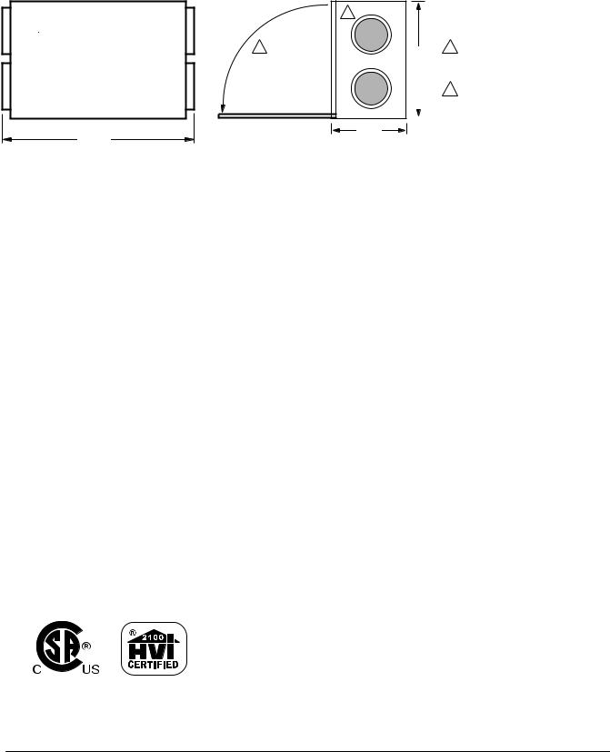
Specifications
Dimensions in inches (mm):
2
1 |
H |
1 |
FRONT CLEARANCE OF 25 INCHES |
|
|
|
(635 MM) IS REQUIRED FOR |
||
|
|
|
|
SERVICING UNIT. |
|
|
|
2 |
ALL DUCT CONNECTIONS ARE |
|
|
|
|
6 IN. (150 MM). |
|
|
|
|
|
|
|
|
|
|
W
L
VNT5150H1000 or VNT5150E1000: H = 22 1/2 in. (572 mm), W = 11 1/2 in. (295 mm), L = 29 1/2 in. (749 mm) VNT5200H1000 or VNT5200E1000: H = 22 1/2 in. (572 mm), W = 16 1/2 in. (422 mm), L = 29 1/2 in. (749 mm)
|
|
|
|
M28919 |
Physical Specifications: |
|
|
|
|
|
|
|
|
|
Model |
Product Weight |
Shipping Weight |
Heat/Energy Core |
Filter Dimensions |
|
|
|
Dimensions |
|
VNT5150H1000 |
|
|
H = 12 in. (305 mm) |
H = 12 in. (305 mm) |
VNT5150E1000 |
42 lbs. (19 kg) |
47.5 lbs. (21.55 kg) |
W = 10 in. (254 mm) |
W = 10 in. (254 mm) |
|
|
|
L = 12 in. (305 mm) |
|
VNT5200H1000 |
|
|
H = 12 in. (305 mm) |
H = 12 in. (305 mm) |
VNT5200E1000 |
50 lbs. (22.68 kg) |
57.5 lbs. (26.08 kg) |
W = 15 in. (381 mm) |
W = 15 in. (381 mm) |
|
|
|
L = 12 in. (305 mm) |
|
Operating Ranges: |
|
Electrical Ratings: |
|
|
Ambient Temperature: 34 to 135 ºF (1 to 57 ºC) |
Input Voltage: 120 VAC, 60 Hz |
|||
Humidity: 0-99% RH |
|
Input Current: 1.5 A |
|
|
|
|
|
Output Power to Terminals: 5 VDC, 1.0 A |
|
|
|
|
|
maximum |
•Drain tubing diameter: 1/2 in. (12.7 mm)
•Flexible Duct (2): 6 in. round for inlet and outlet. Flexible vinyl, compatible for connection to rigid or flexible ducting with sheet metal screws and/or tape.
•Cabinet: 20 gauge galvanized steel
Standards and Certifications:
Install the ERV/HRV Ventilation System according to national and local regulations, building, and safety codes.
4 |
ERV/HRV Ventilation Systems 69-2480EF—01 |
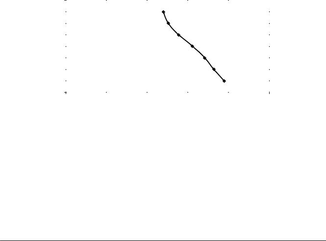
Specifications (continued)
VNT5150H1000 Ventilation Performance
External Static Pressure |
Net Supply Air Flow |
|
|
|
|
|
|
|
|
|
|
Gross Air Flow |
|
|
|||||||||||||||||||||||||||||||||
|
|
|
|
|
Supply |
|
|
|
|
|
|
|
|
|
|
|
|
Exhaust |
|||||||||||||||||||||||||||||
|
|
|
|
|
|
|
|
|
|
|
|
|
|
|
|
|
|
|
|
|
|
|
|
|
|
|
|
|
|
|
|
|
|
|
|
|
|
|
|
|
|||||||
Pa |
|
in. W.C. |
|
|
|
|
L/s |
|
|
|
|
|
|
|
CFM |
|
|
|
L/s |
|
|
|
|
CFM |
|
|
|
|
|
|
L/s |
|
CFM |
||||||||||||||
|
|
|
|
|
|
|
|
|
|
|
|
|
|
|
|
|
|
|
|
|
|
|
|
|
|
|
|
|
|
|
|
|
|
|
|
|
|
|
|
|
|
|
|
|
|
|
|
25 |
|
|
0.1 |
|
|
|
92 |
|
|
|
|
|
|
|
195 |
|
|
|
|
|
92 |
|
|
|
|
196 |
|
|
|
|
|
|
113 |
|
241 |
||||||||||||
|
|
|
|
|
|
|
|
|
|
|
|
|
|
|
|
|
|
|
|
|
|
|
|
|
|
|
|
|
|
|
|
|
|
|
|
|
|
|
|
|
|
|
|
|
|
|
|
50 |
|
|
0.2 |
|
|
|
85 |
|
|
|
|
|
|
|
182 |
|
|
|
|
|
86 |
|
|
|
|
183 |
|
|
|
|
|
|
105 |
|
223 |
||||||||||||
|
|
|
|
|
|
|
|
|
|
|
|
|
|
|
|
|
|
|
|
|
|
|
|
|
|
|
|
|
|
|
|
|
|
|
|
|
|
|
|
|
|
|
|
|
|
|
|
75 |
|
|
0.3 |
|
|
|
80 |
|
|
|
|
|
|
|
171 |
|
|
|
|
|
81 |
|
|
|
|
172 |
|
|
|
|
|
|
91 |
|
193 |
||||||||||||
|
|
|
|
|
|
|
|
|
|
|
|
|
|
|
|
|
|
|
|
|
|
|
|
|
|
|
|
|
|
|
|
|
|
|
|
|
|
|
|
|
|
|
|
|
|
|
|
100 |
|
|
0.4 |
|
|
|
73 |
|
|
|
|
|
|
|
156 |
|
|
|
|
|
74 |
|
|
|
|
157 |
|
|
|
|
|
|
84 |
|
178 |
||||||||||||
125 |
|
|
0.5 |
|
|
|
65 |
|
|
|
|
|
|
|
139 |
|
|
|
|
|
66 |
|
|
|
|
140 |
|
|
|
|
|
|
75 |
|
159 |
||||||||||||
150 |
|
|
0.6 |
|
|
|
59 |
|
|
|
|
|
|
|
126 |
|
|
|
|
|
60 |
|
|
|
|
127 |
|
|
|
|
|
|
65 |
|
137 |
||||||||||||
|
|
|
|
|
|
|
|
|
|
|
|
|
|
|
|
|
|
|
|
|
|
|
|
|
|
|
|
|
|
|
|
|
|
|
|
|
|
|
|
|
|
|
|
|
|
|
|
175 |
|
|
0.7 |
|
|
|
56 |
|
|
|
|
|
|
|
120 |
|
|
|
|
|
57 |
|
|
|
|
120 |
|
|
|
|
|
|
57 |
|
120 |
||||||||||||
|
|
|
|
|
|
|
|
|
|
|
|
|
|
|
|
|
|
|
|
|
|
|
|
|
|
|
|
|
|
|
|
|
|
|
|
|
|
|
|
|
|
|
|
|
|
|
|
200 |
|
|
0.8 |
|
|
|
50 |
|
|
|
|
|
|
|
107 |
|
|
|
|
|
50 |
|
|
|
|
107 |
|
|
|
|
|
|
48 |
|
103 |
||||||||||||
|
|
|
|
|
|
|
|
|
|
|
|
|
|
|
|
|
|
|
|
|
|
|
|
|
|
|
|
|
|
|
|
|
|
|
|
|
|
|
|
|
|
|
|
|
|
|
|
225 |
|
|
0.9 |
|
|
|
45 |
|
|
|
|
|
|
|
95 |
|
|
|
|
|
45 |
|
|
|
|
96 |
|
|
|
|
|
|
40 |
|
86 |
||||||||||||
250 |
|
|
1.0 |
|
|
|
37 |
|
|
|
|
|
|
|
79 |
|
|
|
|
|
38 |
|
|
|
|
80 |
|
|
|
|
|
|
34 |
|
73 |
||||||||||||
|
|
|
|
|
|
|
|
|
|
|
|
|
|
|
|
|
|
|
|
|
VNT5150H1000 |
|
|
|
|
|
|
|
|
|
|
|
|
|
|
|
|
|
|
|
|||||||
|
|
|
|
|
|
|
|
|
|
|
|
|
|
|
|
|
|
|
|
|
AIR FLOW (L/S) |
|
|
|
|
|
|
|
|
|
|
|
|
|
|
|
|
|
|
|
|
|
|||||
|
|
|
0.8 |
0 |
10 |
20 |
|
30 |
|
40 |
50 |
60 |
70 |
80 |
|
90 |
|
100 |
110 |
|
|
200 |
|
|
|||||||||||||||||||||||
|
|
|
0.7 |
|
|
|
|
|
|
|
|
|
|
|
|
|
|
|
|
|
|
|
|
|
|
|
|
|
|
|
|
|
|
|
|
|
|
|
|
|
|
|
|
|
175 |
|
|
|
|
|
|
|
|
|
|
|
|
|
|
|
|
|
|
|
|
|
|
|
|
|
|
|
|
|
|
|
|
|
|
|
|
|
|
|
|
|
|
|
|
|
|
|
|
||
|
|
|
0.6 |
|
|
|
|
|
|
|
|
|
|
|
|
|
|
|
|
|
|
|
|
|
|
|
|
|
|
|
|
|
|
|
|
|
|
|
|
|
|
|
|
|
150 |
|
|
|
|
|
|
|
|
|
|
|
|
|
|
|
|
|
|
|
|
|
|
|
|
|
|
|
|
|
|
|
|
|
|
|
|
|
|
|
|
|
|
|
|
|
|
|
|
||
|
EXTERNAL |
0.5 |
|
|
|
|
|
|
|
|
|
|
|
|
|
|
|
|
|
|
|
|
|
|
|
|
|
|
|
|
|
|
|
|
|
|
|
|
|
|
|
|
|
125 |
|
|
|
|
|
|
|
|
|
|
|
|
|
|
|
|
|
|
|
|
|
|
|
|
|
|
|
|
|
|
|
|
|
|
|
|
|
|
|
|
|
|
|
|
|
|
|
||||
|
|
|
|
|
|
|
|
|
|
|
|
|
|
|
|
|
|
|
|
|
|
|
|
|
|
|
|
|
|
|
|
|
|
|
|
|
|
|
|
|
|
|
EXTERNAL |
||||
|
|
STATIC |
0.4 |
|
|
|
|
|
|
|
|
|
|
|
|
|
|
|
|
|
|
|
|
|
|
|
|
|
|
|
|
|
|
|
|
|
|
|
|
|
|
|
|
|
100 |
STATIC |
|
|
|
|
|
|
|
|
|
|
|
|
|
|
|
|
|
|
|
|
|
|
|
|
|
|
|
|
|
|
|
|
|
|
|
|
|
|
|
|
|
|
|
|
|||||
|
PRESSURE |
|
|
|
|
|
|
|
|
|
|
|
|
|
|
|
|
|
|
|
|
|
|
|
|
|
|
|
|
|
|
|
|
|
|
|
|
|
|
|
|
|
|
PRESSURE |
|||
|
(IN. W. C) |
0.3 |
|
|
|
|
|
|
|
|
|
|
|
|
|
|
|
|
|
|
|
|
|
|
|
|
|
|
|
|
|
|
|
|
|
|
|
|
|
|
|
|
|
75 |
(PA) |
||
|
|
|
|
|
|
|
|
|
|
|
|
|
|
|
|
|
|
|
|
|
|
|
|
|
|
|
|
|
|
|
|
|
|
|
|
|
|
|
|
|
|
|
|
|
|
||
|
|
|
0.2 |
|
|
|
|
|
|
|
|
|
|
|
|
|
|
|
|
|
|
|
|
|
|
|
|
|
|
|
|
|
|
|
|
|
|
|
|
|
|
|
|
|
50 |
|
|
|
|
|
|
|
|
|
|
|
|
|
|
|
|
|
|
|
|
|
|
|
|
|
|
|
|
|
|
|
|
|
|
|
|
|
|
|
|
|
|
|
|
|
|
|
|
||
|
|
|
|
|
|
|
|
NET SUPPLY AIR FLOW |
|
|
|
|
|
|
|
|
|
|
|
|
|
|
|
|
|
|
|
|
|
|
|
|
|
|
|
|
|
|
|
||||||||
|
|
|
0.1 |
|
|
|
|
|
|
|
|
|
|
|
|
|
|
|
|
|
|
|
|
|
|
|
|
|
|
|
|
|
|
|
|
|
|
|
|
|
|
|
|
|
25 |
|
|
|
|
|
0 |
|
|
|
|
|
|
|
|
|
|
|
|
|
|
|
|
|
|
|
|
|
|
|
|
|
|
|
|
|
|
|
|
|
|
|
|
|
|
|
|
|
0 |
|
|
|
|
|
|
0 |
|
|
|
50 |
|
|
|
|
|
|
|
100 AIR FLOW (CFM) 150 |
|
|
|
|
200 |
|
|
|
|
|
|
250 |
M32358 |
||||||||||||||||||
VNT5150H1000 Energy Performance
|
Supply Temperature |
Net Supply Air Flow |
Average |
Sensible |
Apparent |
|||
|
Power |
Recovery |
Sensible |
|||||
|
|
|
|
|
||||
|
|
|
|
|
|
|
|
|
|
°C |
°F |
L/s |
CFM |
Watts |
Efficiency % |
Effectiveness % |
|
Heating |
0 |
32 |
31 |
66 |
88 |
66 |
78 |
|
0 |
32 |
42 |
89 |
104 |
64 |
76 |
||
|
||||||||
|
|
|
|
|
|
|
|
|
|
0 |
32 |
56 |
119 |
114 |
63 |
72 |
|
|
|
|
|
|
|
|
|
|
|
-25 |
-13 |
32 |
67 |
86 |
59 |
77 |
|
|
|
|
|
|
|
|
|
|
ERV/HRV Ventilation Systems 69-2480EF—01 |
5 |
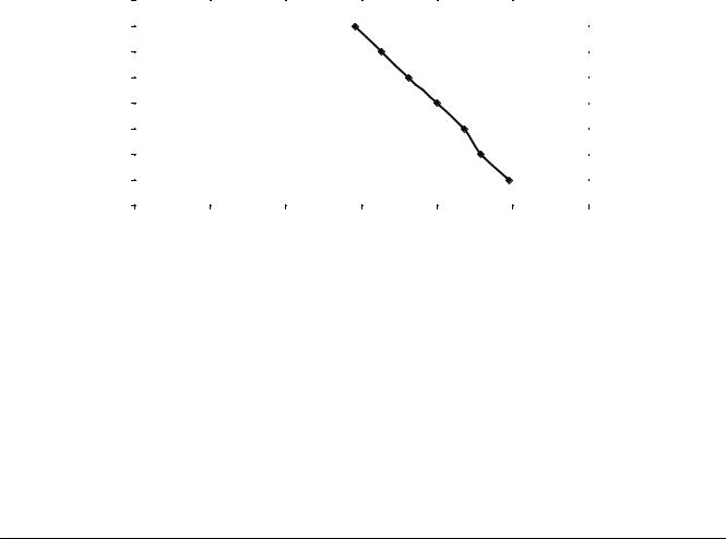
Specifications (continued)
VNT5200H1000 Ventilation Performance
|
|
External Static |
|
|
|
|
|
Net Supply Air Flow |
|
|
|
|
|
|
|
|
|
|
|
|
|
|
|
|
Gross Air Flow |
|
|
|
||||||||||||||||||||||||||||||||
|
|
|
Pressure |
|
|
|
|
|
|
|
|
|
|
|
|
|
|
|
|
Supply |
|
|
|
|
|
|
|
|
|
|
|
|
|
Exhaust |
||||||||||||||||||||||||||
|
|
|
|
|
|
|
|
|
|
|
|
|
|
|
|
|
|
|
|
|
|
|
|
|
|
|
|
|
|
|
|
|
|
|
|
|
|
|
|
|
|
|
|
|
|
|
|
|||||||||||||
|
|
Pa |
|
in. W.C. |
|
|
|
|
|
L/s |
|
|
|
|
|
|
|
CFM |
|
|
|
|
|
|
L/s |
|
|
|
|
CFM |
|
|
|
|
L/s |
|
CFM |
|||||||||||||||||||||||
|
|
|
|
|
|
|
|
|
|
|
|
|
|
|
|
|
|
|
|
|
|
|
|
|
|
|
|
|
|
|
|
|
|
|
|
|
|
|
|
|
|
|
|
|
|
|
|
|
|
|
|
|
|
|
|
|
|
|
|
|
|
25 |
|
|
|
0.1 |
|
|
|
|
|
|
|
|
117 |
|
|
|
|
|
|
|
248 |
|
|
|
|
|
|
118 |
|
|
|
|
|
|
|
250 |
|
|
|
|
|
|
|
130 |
|
277 |
|
||||||||||||
|
|
|
|
|
|
|
|
|
|
|
|
|
|
|
|
|
|
|
|
|
|
|
|
|
|
|
|
|
|
|
|
|
|
|
|
|
|
|
|
|
|
|
|
|
|
|
|
|
|
|
|
|
|
|
|
|
|
|
|
|
|
50 |
|
|
|
0.2 |
|
|
|
|
|
|
|
|
108 |
|
|
|
|
|
|
|
229 |
|
|
|
|
|
|
109 |
|
|
|
|
|
|
|
231 |
|
|
|
|
|
|
|
119 |
|
253 |
|
||||||||||||
|
|
|
|
|
|
|
|
|
|
|
|
|
|
|
|
|
|
|
|
|
|
|
|
|
|
|
|
|
|
|
|
|
|
|
|
|
|
|
|
|
|
|
|
|
|
|
|
|
|
|
|
|
|
|
|
|
|
|
|
|
|
75 |
|
|
|
0.3 |
|
|
|
|
|
|
|
|
102 |
|
|
|
|
|
|
|
218 |
|
|
|
|
|
|
103 |
|
|
|
|
|
|
|
220 |
|
|
|
|
|
|
|
110 |
|
234 |
|
||||||||||||
|
|
|
|
|
|
|
|
|
|
|
|
|
|
|
|
|
|
|
|
|
|
|
|
|
|
|
|
|
|
|
|
|
|
|
|
|
|
|
|
|
|
|
|
|
|
|
|
|
|
|
|
|
|
|
|
|
|
|
|
|
|
100 |
|
|
|
0.4 |
|
|
|
|
|
|
|
|
94 |
|
|
|
|
|
|
|
200 |
|
|
|
|
|
|
95 |
|
|
|
|
|
|
|
202 |
|
|
|
|
|
|
|
101 |
|
216 |
|
||||||||||||
|
125 |
|
|
|
0.5 |
|
|
|
|
|
|
|
|
85 |
|
|
|
|
|
|
|
181 |
|
|
|
|
|
|
86 |
|
|
|
|
|
|
|
183 |
|
|
|
|
|
|
|
92 |
|
197 |
|
||||||||||||
|
150 |
|
|
|
0.6 |
|
|
|
|
|
|
|
|
77 |
|
|
|
|
|
|
|
163 |
|
|
|
|
|
|
78 |
|
|
|
|
|
|
|
165 |
|
|
|
|
|
|
|
82 |
|
175 |
|
||||||||||||
|
|
|
|
|
|
|
|
|
|
|
|
|
|
|
|
|
|
|
|
|
|
|
|
|
|
|
|
|
|
|
|
|
|
|
|
|
|
|
|
|
|
|
|
|
|
|
|
|
|
|
|
|
|
|
|
|
|
|
|
|
|
175 |
|
|
|
0.7 |
|
|
|
|
|
|
|
|
69 |
|
|
|
|
|
|
|
146 |
|
|
|
|
|
|
70 |
|
|
|
|
|
|
|
148 |
|
|
|
|
|
|
|
71 |
|
151 |
|
||||||||||||
|
|
|
|
|
|
|
|
|
|
|
|
|
|
|
|
|
|
|
|
|
|
|
|
|
|
|
|
|
|
|
|
|
|
|
|
|
|
|
|
|
|
|
|
|
|
|
|
|
|
|
|
|
|
|
|
|
|
|
|
|
|
200 |
|
|
|
0.8 |
|
|
|
|
|
|
|
|
61 |
|
|
|
|
|
|
|
129 |
|
|
|
|
|
|
61 |
|
|
|
|
|
|
|
131 |
|
|
|
|
|
|
|
60 |
|
128 |
|
||||||||||||
|
|
|
|
|
|
|
|
|
|
|
|
|
|
|
|
|
|
|
|
|
|
|
|
|
|
|
|
|
|
|
|
|
|
|
|
|
|
|
|
|
|
|
|
|
|
|
|
|
|
|
|
|
|
|
|
|
|
|
|
|
|
225 |
|
|
|
0.9 |
|
|
|
|
|
|
|
|
52 |
|
|
|
|
|
|
|
110 |
|
|
|
|
|
|
52 |
|
|
|
|
|
|
|
111 |
|
|
|
|
|
|
|
49 |
|
104 |
|
||||||||||||
|
250 |
|
|
|
1.0 |
|
|
|
|
|
|
|
|
45 |
|
|
|
|
|
|
|
96 |
|
|
|
|
|
|
|
|
46 |
|
|
|
|
|
|
|
97 |
|
|
|
|
|
|
|
40 |
|
86 |
|
||||||||||
|
|
|
|
|
|
|
|
|
|
|
|
|
|
|
|
|
|
|
|
|
|
|
|
|
|
|
|
VNT5200H1000 |
|
|
|
|
|
|
|
|
|
|
|
|
|
|
|
|
|
|
|
|
||||||||||||
|
|
|
|
|
|
|
|
|
|
|
|
|
|
|
|
|
|
|
|
|
|
|
|
|
|
|
|
AIR FLOW (L/S) |
|
|
|
|
|
|
|
|
|
|
|
|
|
|
|
|
|
|
|
|
|
|
|
|
||||||||
|
|
|
|
|
|
0.8 |
0 |
|
10 |
|
20 |
30 |
40 |
50 |
60 |
70 |
80 |
90 |
|
100 |
110 |
120 |
130 |
140 |
200 |
|
|
|
||||||||||||||||||||||||||||||||
|
|
|
|
|
|
0.7 |
|
|
|
|
|
|
|
|
|
|
|
|
|
|
|
|
|
|
|
|
|
|
|
|
|
|
|
|
|
|
|
|
|
|
|
|
|
|
|
|
|
|
|
|
|
|
|
|
|
|
175 |
|
|
|
|
|
|
|
|
|
|
|
|
|
|
|
|
|
|
|
|
|
|
|
|
|
|
|
|
|
|
|
|
|
|
|
|
|
|
|
|
|
|
|
|
|
|
|
|
|
|
|
|
|
|
|
|
|
|
|
|
|
|
||
|
|
|
|
|
|
0.6 |
|
|
|
|
|
|
|
|
|
|
|
|
|
|
|
|
|
|
|
|
|
|
|
|
|
|
|
|
|
|
|
|
|
|
|
|
|
|
|
|
|
|
|
|
|
|
|
|
|
|
150 |
|
|
|
|
|
|
|
|
|
|
|
|
|
|
|
|
|
|
|
|
|
|
|
|
|
|
|
|
|
|
|
|
|
|
|
|
|
|
|
|
|
|
|
|
|
|
|
|
|
|
|
|
|
|
|
|
|
|
|
|
|
|
||
|
|
|
EXTERNAL |
0.5 |
|
|
|
|
|
|
|
|
|
|
|
|
|
|
|
|
|
|
|
|
|
|
|
|
|
|
|
|
|
|
|
|
|
|
|
|
|
|
|
|
|
|
|
|
|
|
|
|
|
|
125 |
EXTERNAL |
||||
|
|
|
|
|
|
|
|
|
|
|
|
|
|
|
|
|
|
|
|
|
|
|
|
|
|
|
|
|
|
|
|
|
|
|
|
|
|
|
|
|
|
|
|
|
|
|
|
|
|
|
|
|
||||||||
|
|
|
|
|
|
|
|
|
|
|
|
|
|
|
|
|
|
|
|
|
|
|
|
|
|
|
|
|
|
|
|
|
|
|
|
|
|
|
|
|
|
|
|
|
|
|
|
|
|
|
|
|
|
|
||||||
|
|
|
STATIC |
0.4 |
|
|
|
|
|
|
|
|
|
|
|
|
|
|
|
|
|
|
|
|
|
|
|
|
|
|
|
|
|
|
|
|
|
|
|
|
|
|
|
|
|
|
|
|
|
|
|
|
|
|
100 |
STATIC |
||||
|
|
|
PRESSURE |
|
|
|
|
|
|
|
|
|
|
|
|
|
|
|
|
|
|
|
|
|
|
|
|
|
|
|
|
|
|
|
|
|
|
|
|
|
|
|
|
|
|
|
|
|
|
|
|
|
|
|
|
PRESSURE |
||||
|
|
|
(IN. W. C) |
0.3 |
|
|
|
|
|
|
|
|
|
|
|
|
|
|
|
|
|
|
|
|
|
|
|
|
|
|
|
|
|
|
|
|
|
|
|
|
|
|
|
|
|
|
|
|
|
|
|
|
|
|
75 |
(PA) |
||||
|
|
|
|
|
|
|
|
|
|
|
|
|
|
|
|
|
|
|
|
|
|
|
|
|
|
|
|
|
|
|
|
|
|
|
|
|
|
|
|
|
|
|
|
|
|
|
|
|
|
|
|
|
|
|
|
|
|
|
||
|
|
|
|
|
|
0.2 |
|
|
|
|
|
|
|
|
|
|
|
|
|
|
|
|
|
|
|
|
|
|
|
|
|
|
|
|
|
|
|
|
|
|
|
|
|
|
|
|
|
|
|
|
|
|
|
|
|
|
50 |
|
|
|
|
|
|
|
|
|
|
|
|
|
|
|
|
|
|
|
|
|
|
|
|
|
|
|
|
|
|
|
|
|
|
|
|
|
|
|
|
|
|
|
|
|
|
|
|
|
|
|
|
|
|
|
|
|
|
|
|
|
|
||
|
|
|
|
|
|
0.1 |
|
|
|
|
|
|
|
|
|
|
|
|
|
|
|
|
|
|
|
|
|
|
|
|
|
|
|
|
|
|
|
|
|
|
|
|
|
|
|
|
|
|
|
|
|
|
|
|
|
|
25 |
|
|
|
|
|
|
|
|
|
|
|
|
|
NET SUPPLY AIR FLOW |
|
|
|
|
|
|
|
|
|
|
|
|
|
|
|
|
|
|
|
|
|
|
|
|
|
|
|
|
|
|
|
|
|
|
|
|
|
|
||||||||||||
|
|
|
|
|
|
0 |
|
|
|
|
|
|
|
|
|
|
|
|
|
|
|
|
|
|
|
|
|
|
|
|
|
|
|
|
|
|
|
|
|
|
|
|
|
|
|
|
|
|
|
|
|
|
|
|
|
|
0 |
|
|
|
|
|
|
|
|
|
|
0 |
|
|
|
|
|
|
|
|
50 |
|
|
|
|
|
100 |
|
|
|
|
|
150 |
|
|
|
200 |
|
|
|
|
250 |
|
|
|
|
|
|
300 |
|
|
|
|||||||||||||
|
|
|
|
|
|
|
|
|
|
|
|
|
|
|
|
|
|
|
|
|
|
|
|
|
|
|
|
|
AIR FLOW (CFM) |
|
|
|
|
|
|
|
|
|
|
|
|
|
|
|
|
|
M32354 |
|||||||||||||
VNT5200H1000 Energy Performance |
|
|
|
|
|
|
|
|
|
|
|
|
|
|
|
|
|
|
|
|
|
|
|
|
|
|
|
|
|
|
|
|
|
|||||||||||||||||||||||||||
|
|
|
|
|
|
|
|
|
|
|
|
|
|
|
|
|
|
|
|
|
|
|
|
|
|
|
|
|
|
|
|
|
|
|
|
|
|
|
|
|
|
|
|
|
|
|
|
|
|
|
|
|
|
|
|
|
||||
|
|
Supply Temperature |
|
Net Supply Air Flow |
|
|
|
Average |
|
|
|
|
|
|
Sensible |
|
|
|
Apparent |
|
||||||||||||||||||||||||||||||||||||||||
|
|
|
|
|
|
Power |
|
|
|
|
|
|
Recovery |
|
|
|
Sensible |
|
||||||||||||||||||||||||||||||||||||||||||
|
|
|
|
|
|
|
|
|
|
|
|
|
|
|
|
|
|
|
|
|
|
|
|
|
|
|
|
|
|
|
|
|
|
|
|
|
|
|
|
|
|
|
|
|||||||||||||||||
|
|
|
°C |
|
|
|
°F |
|
|
|
|
|
|
|
|
L/s |
|
|
|
|
CFM |
|
|
|
Watts |
|
|
|
|
Efficiency % |
|
|
Effectiveness % |
|
||||||||||||||||||||||||||
|
|
|
|
|
|
|
|
|
|
|
|
|
|
|
|
|
|
|
|
|
|
|
|
|
|
|
|
|
|
|
|
|
|
|
|
|
|
|
|
|
|
|
|
|
|
|
|
|
|
|
|
|
|
|
|
|
|
|||
|
Heating |
|
0 |
|
|
|
32 |
|
|
|
|
|
|
|
|
55 |
|
|
|
118 |
|
|
|
|
|
106 |
|
|
|
|
|
|
|
|
|
|
61 |
|
|
|
|
|
|
|
71 |
|
||||||||||||||
|
|
|
|
|
|
|
|
|
|
|
|
|
|
|
|
|
|
|
|
|
|
|
|
|
|
|
|
|
|
|
|
|
|
|
|
|
|
|
|
|
|
|
|
|
|
|
|
|
|
|
|
|
|
|
|
|
|
|
|
|
|
|
0 |
|
|
|
32 |
|
|
|
|
|
|
|
|
75 |
|
|
|
160 |
|
|
|
|
|
132 |
|
|
|
|
|
|
|
|
|
|
58 |
|
|
|
|
|
|
|
65 |
|
|||||||||||||||
|
|
|
|
|
|
|
|
|
|
|
|
|
|
|
|
|
|
|
|
|
|
|
|
|
|
|
|
|
|
|
|
|
|
|
|
|
|
|
|
|||||||||||||||||||||
|
|
|
|
|
|
|
|
|
|
|
|
|
|
|
|
|
|
|
|
|
|
|
|
|
|
|
|
|
|
|
|
|
|
|
|
|
|
|
|
|
|
|
|
|
|
|
|
|
|
|
|
|
|
|
|
|
|
|||
|
|
|
0 |
|
|
|
32 |
|
|
|
|
|
|
|
|
87 |
|
|
|
185 |
|
|
|
|
|
150 |
|
|
|
|
|
|
|
|
|
|
55 |
|
|
|
|
|
|
|
62 |
|
||||||||||||||
|
|
|
|
|
|
|
|
|
|
|
|
|
|
|
|
|
|
|
|
|
|
|
|
|
|
|
|
|
|
|
|
|
|
|
|
|
|
|
|
|
|
|
|
|
|
|
|
|
|
|
|
|
|
|
|
|
|
|||
|
|
|
-25 |
|
|
|
-13 |
|
|
|
|
|
|
|
57 |
|
|
|
120 |
|
|
|
|
|
105 |
|
|
|
|
|
|
|
|
|
|
58 |
|
|
|
|
|
|
|
72 |
|
|||||||||||||||
6 |
ERV/HRV Ventilation Systems 69-2480EF—01 |
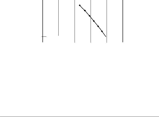
Specifications (continued)
VNT5150E1000 Ventilation Performance
External Static Pressure |
|
Net Supply Air Flow |
|
|
|
|
|
|
|
|
|
|
|
|
Gross Air Flow |
|
|||||||||||||||||||||||||
|
|
|
|
|
|
|
Supply |
|
|
|
|
|
|
|
|
|
Exhaust |
||||||||||||||||||||||||
|
|
|
|
|
|
|
|
|
|
|
|
|
|
|
|
|
|
|
|
|
|
|
|
|
|
|
|
|
|
|
|
|
|
||||||||
Pa |
in. W.C. |
|
|
L/s |
|
|
|
|
|
|
CFM |
|
|
|
L/s |
|
|
|
|
|
|
CFM |
|
|
|
|
|
|
L/s |
CFM |
|||||||||||
|
|
|
|
|
|
|
|
|
|
|
|
|
|
|
|
|
|
|
|
|
|
|
|
|
|
|
|
|
|
|
|
|
|
|
|
|
|
|
|
|
|
25 |
0.1 |
|
|
92 |
|
|
|
|
|
|
197 |
|
|
|
|
|
|
96 |
|
|
|
|
|
|
204 |
|
|
|
|
|
|
93 |
199 |
||||||||
|
|
|
|
|
|
|
|
|
|
|
|
|
|
|
|
|
|
|
|
|
|
|
|
|
|
|
|
|
|
|
|
|
|
|
|
|
|
|
|
|
|
50 |
0.2 |
|
|
87 |
|
|
|
|
|
|
185 |
|
|
|
|
|
|
93 |
|
|
|
|
|
|
199 |
|
|
|
|
|
|
88 |
186 |
||||||||
|
|
|
|
|
|
|
|
|
|
|
|
|
|
|
|
|
|
|
|
|
|
|
|
|
|
|
|
|
|
|
|
|
|
|
|
|
|
|
|
|
|
75 |
0.3 |
|
|
82 |
|
|
|
|
|
|
173 |
|
|
|
|
|
|
88 |
|
|
|
|
|
|
186 |
|
|
|
|
|
|
82 |
175 |
||||||||
|
|
|
|
|
|
|
|
|
|
|
|
|
|
|
|
|
|
|
|
|
|
|
|
|
|
|
|
|
|
|
|
|
|
|
|
|
|
|
|
|
|
100 |
0.4 |
|
|
75 |
|
|
|
|
|
|
160 |
|
|
|
|
|
|
83 |
|
|
|
|
|
|
176 |
|
|
|
|
|
|
76 |
162 |
||||||||
125 |
0.5 |
|
|
69 |
|
|
|
|
|
|
146 |
|
|
|
|
|
|
76 |
|
|
|
|
|
|
162 |
|
|
|
|
|
|
70 |
148 |
||||||||
150 |
0.6 |
|
|
62 |
|
|
|
|
|
|
132 |
|
|
|
|
|
|
72 |
|
|
|
|
|
|
152 |
|
|
|
|
|
|
63 |
134 |
||||||||
|
|
|
|
|
|
|
|
|
|
|
|
|
|
|
|
|
|
|
|
|
|
|
|
|
|
|
|
|
|
|
|
|
|
|
|
|
|
|
|
|
|
175 |
0.7 |
|
|
55 |
|
|
|
|
|
|
116 |
|
|
|
|
|
|
67 |
|
|
|
|
|
|
143 |
|
|
|
|
|
|
55 |
117 |
||||||||
|
|
|
|
|
|
|
|
|
|
|
|
|
|
|
|
|
|
|
|
|
|
|
|
|
|
|
|
|
|
|
|
|
|
|
|
|
|
|
|
|
|
200 |
0.8 |
|
|
48 |
|
|
|
|
|
|
102 |
|
|
|
|
|
|
60 |
|
|
|
|
|
|
127 |
|
|
|
|
|
|
48 |
103 |
||||||||
|
|
|
|
|
|
|
|
|
|
|
|
|
|
|
|
|
|
|
|
|
|
|
|
|
|
|
|
|
|
|
|
|
|
|
|
|
|
|
|
|
|
225 |
0.9 |
|
|
41 |
|
|
|
|
|
|
88 |
|
|
|
|
|
|
54 |
|
|
|
|
|
|
114 |
|
|
|
|
|
|
42 |
89 |
||||||||
250 |
1.0 |
|
|
38 |
|
|
|
|
|
|
81 |
|
|
|
|
|
|
42 |
|
|
|
|
|
|
89 |
|
|
|
|
|
|
39 |
82 |
||||||||
|
|
|
|
|
|
|
|
|
|
|
|
|
|
|
VNT5150E1000 |
|
|
|
|
|
|
|
|
|
|
|
|
|
|
|
|
|
|||||||||
|
|
|
|
|
|
|
|
|
|
|
|
|
|
|
|
AIR FLOW (L/S) |
|
|
|
|
|
|
|
|
|
|
|
|
|
|
|
|
|
|
|
|
|||||
|
|
0 |
10 |
20 |
30 |
40 |
50 |
60 |
70 |
80 |
90 |
100 |
110 |
|
|
200 |
|
|
|||||||||||||||||||||||
|
|
0.8 |
|
|
|
|
|
|
|
|
|
|
|
|
|
|
|
|
|
|
|
|
|
|
|
|
|
|
|
|
|
|
|
|
|
|
|
|
|
|
|
|
|
|
|
|
|
|
|
|
|
|
|
|
|
|
|
|
|
|
|
|
|
|
|
|
|
|
|
|
|
|
|
|
|
|
|
|
|
|
|
||
|
|
0.7 |
|
|
|
|
|
|
|
|
|
|
|
|
|
|
|
|
|
|
|
|
|
|
|
|
|
|
|
|
|
|
|
|
|
|
|
|
175 |
|
|
|
|
|
|
|
|
|
|
|
|
|
|
|
|
|
|
|
|
|
|
|
|
|
|
|
|
|
|
|
|
|
|
|
|
|
|
|
|
|
|
||
|
|
0.6 |
|
|
|
|
|
|
|
|
|
|
|
|
|
|
|
|
|
|
|
|
|
|
|
|
|
|
|
|
|
|
|
|
|
|
|
|
150 |
|
|
|
|
|
|
|
|
|
|
|
|
|
|
|
|
|
|
|
|
|
|
|
|
|
|
|
|
|
|
|
|
|
|
|
|
|
|
|
|
|
|
||
|
EXTERNAL |
0.5 |
|
|
|
|
|
|
|
|
|
|
|
|
|
|
|
|
|
|
|
|
|
|
|
|
|
|
|
|
|
|
|
|
|
|
|
|
125 |
EXTERNAL |
|
|
|
|
|
|
|
|
|
|
|
|
|
|
|
|
|
|
|
|
|
|
|
|
|
|
|
|
|
|
|
|
|
|
|
|
|
|
|
||||
|
|
|
|
|
|
|
|
|
|
|
|
|
|
|
|
|
|
|
|
|
|
|
|
|
|
|
|
|
|
|
|
|
|
|
|
|
|
|
|
||
|
STATIC |
0.4 |
|
|
|
|
|
|
|
|
|
|
|
|
|
|
|
|
|
|
|
|
|
|
|
|
|
|
|
|
|
|
|
|
|
|
|
|
100 |
STATIC |
|
|
|
|
|
|
|
|
|
|
|
|
|
|
|
|
|
|
|
|
|
|
|
|
|
|
|
|
|
|
|
|
|
|
|
|
|
|
|
||||
|
PRESSURE |
|
|
|
|
|
|
|
|
|
|
|
|
|
|
|
|
|
|
|
|
|
|
|
|
|
|
|
|
|
|
|
|
|
|
|
|
|
|
PRESSURE |
|
|
(IN. W. C) |
0.3 |
|
|
|
|
|
|
|
|
|
|
|
|
|
|
|
|
|
|
|
|
|
|
|
|
|
|
|
|
|
|
|
|
|
|
|
|
75 |
(PA) |
|
|
|
|
|
|
|
|
|
|
|
|
|
|
|
|
|
|
|
|
|
|
|
|
|
|
|
|
|
|
|
|
|
|
|
|
|
|
|
||||
|
|
0.2 |
|
|
|
|
|
|
|
|
|
|
|
|
|
|
|
|
|
|
|
|
|
|
|
|
|
|
|
|
|
|
|
|
|
|
|
|
50 |
|
|
|
|
|
|
|
|
|
|
|
|
|
|
|
|
|
|
|
|
|
|
|
|
|
|
|
|
|
|
|
|
|
|
|
|
|
|
|
|
|
|
||
0.1NET SUPPLY AIR FLOW  25
25
0.0 |
|
|
|
|
|
|
|
|
|
|
|
0 |
0 |
50 |
100 |
150 |
200 |
250 |
|||||||
AIR FLOW (CFM) |
M32370 |
|
VNT5150E1000 Energy Performance
|
Supply Temperature |
Net Supply Air Flow |
Average |
Sensible |
Apparent |
||
|
Power |
Recovery |
Sensible |
||||
|
|
|
|
|
|||
|
|
|
|
|
|
|
|
|
°C |
°F |
L/s |
CFM |
Watts |
Efficiency % |
Effectiveness % |
|
|
|
|
|
|
|
|
|
0 |
32 |
30 |
64 |
75 |
52 |
67 |
Heating |
|
|
|
|
|
|
|
0 |
32 |
45 |
96 |
100 |
44 |
64 |
|
-15 |
5 |
30 |
64 |
80 |
52 |
67 |
|
|
0 |
32 |
55 |
117 |
126 |
40 |
62 |
|
|
|
|
|
|
|
|
|
35 |
95 |
30 |
64 |
75 |
|
|
|
|
|
|
|
|
Total Recovery Efficiency = 49% |
|
|
|
|
|
|
|
||
ERV/HRV Ventilation Systems 69-2480EF—01 |
7 |

Specifications (continued)
VNT5200E1000 Ventilation Performance
External Static |
Net Supply Air Flow |
|
|
Gross Air Flow |
|
|
||||
|
Pressure |
|
Supply |
|
Exhaust |
|||||
|
|
|
|
|
||||||
Pa |
|
in. W.C. |
L/s |
CFM |
L/s |
|
CFM |
L/s |
|
CFM |
|
|
|
|
|
|
|
|
|
|
|
25 |
|
0.1 |
98 |
208 |
102 |
|
218 |
99 |
|
210 |
|
|
|
|
|
|
|
|
|
|
|
50 |
|
0.2 |
94 |
200 |
99 |
|
210 |
95 |
|
202 |
|
|
|
|
|
|
|
|
|
|
|
75 |
|
0.3 |
87 |
186 |
93 |
|
199 |
88 |
|
188 |
|
|
|
|
|
|
|
|
|
|
|
100 |
|
0.4 |
82 |
175 |
88 |
|
188 |
83 |
|
176 |
125 |
|
0.5 |
74 |
157 |
78 |
|
167 |
75 |
|
159 |
150 |
|
0.6 |
65 |
138 |
72 |
|
152 |
65 |
|
139 |
|
|
|
|
|
|
|
|
|
|
|
175 |
|
0.7 |
60 |
127 |
64 |
|
135 |
60 |
|
128 |
|
|
|
|
|
|
|
|
|
|
|
200 |
|
0.8 |
53 |
112 |
60 |
|
127 |
53 |
|
113 |
|
|
|
|
|
|
|
|
|
|
|
225 |
|
0.9 |
44 |
94 |
54 |
|
114 |
45 |
|
95 |
250 |
|
1 |
38 |
81 |
41 |
|
86 |
39 |
|
82 |
VNT5200E1000
AIR FLOW (L/S)
|
0.8 |
0 |
10 |
20 |
30 |
40 |
50 |
60 |
70 |
80 |
90 |
100 |
110 |
200 |
|
|||||||||||||||||||||||||
|
|
|
|
|
|
|
|
|
|
|
|
|
|
|
|
|
|
|
|
|
|
|
|
|
|
|
|
|
|
|
|
|
|
|
|
|
|
|
||
|
|
|
|
|
|
|
|
|
|
|
|
|
|
|
|
|
|
|
|
|
|
|
|
|
|
|
|
|
|
|
|
|
|
|
|
|
|
|
||
|
0.7 |
|
|
|
|
|
|
|
|
|
|
|
|
|
|
|
|
|
|
|
|
|
|
|
|
|
|
|
|
|
|
|
|
|
|
|
|
|
175 |
|
|
|
|
|
|
|
|
|
|
|
|
|
|
|
|
|
|
|
|
|
|
|
|
|
|
|
|
|
|
|
|
|
|
|
|
|
|
|
|
||
|
0.6 |
|
|
|
|
|
|
|
|
|
|
|
|
|
|
|
|
|
|
|
|
|
|
|
|
|
|
|
|
|
|
|
|
|
|
|
|
|
150 |
|
|
|
|
|
|
|
|
|
|
|
|
|
|
|
|
|
|
|
|
|
|
|
|
|
|
|
|
|
|
|
|
|
|
|
|
|
|
|
|
||
EXTERNAL |
0.5 |
|
|
|
|
|
|
|
|
|
|
|
|
|
|
|
|
|
|
|
|
|
|
|
|
|
|
|
|
|
|
|
|
|
|
|
|
|
125 |
EXTERNAL |
|
|
|
|
|
|
|
|
|
|
|
|
|
|
|
|
|
|
|
|
|
|
|
|
|
|
|
|
|
|
|
|
|
|
|
|
|
||||
|
|
|
|
|
|
|
|
|
|
|
|
|
|
|
|
|
|
|
|
|
|
|
|
|
|
|
|
|
|
|
|
|
|
|
|
|
|
|
||
STATIC |
|
|
|
|
|
|
|
|
|
|
|
|
|
|
|
|
|
|
|
|
|
|
|
|
|
|
|
|
|
|
|
|
|
|
|
|
|
|
|
STATIC |
PRESSURE |
0.4 |
|
|
|
|
|
|
|
|
|
|
|
|
|
|
|
|
|
|
|
|
|
|
|
|
|
|
|
|
|
|
|
|
|
|
|
|
|
100 PRESSURE |
|
(IN. W. C) |
0.3 |
|
|
|
|
|
|
|
|
|
|
|
|
|
|
|
|
|
|
|
|
|
|
|
|
|
|
|
|
|
|
|
|
|
|
|
|
|
75 |
(PA) |
|
|
|
|
|
|
|
|
|
|
|
|
|
|
|
|
|
|
|
|
|
|
|
|
|
|
|
|
|
|
|
|
|
|
|
|
|
||||
|
0.2 |
|
|
|
|
|
|
|
|
|
|
|
|
|
|
|
|
|
|
|
|
|
|
|
|
|
|
|
|
|
|
|
|
|
|
|
|
|
50 |
|
|
|
|
|
|
|
|
|
|
|
|
|
|
|
|
|
|
|
|
|
|
|
|
|
|
|
|
|
|
|
|
|
|
|
|
|
|
|
|
||
|
0.1 |
|
|
|
|
|
|
|
|
|
|
|
|
|
|
|
|
|
|
|
|
|
|
|
|
|
|
|
|
|
|
|
|
|
|
|
|
|
25 |
|
|
|
NET SUPPLY |
AIR FLOW |
|
|
|
|
|
|
|
|
|
|
|
|
|
|
|
|
|
|
|
|
|
|
|
|
|||||||||||||
|
|
|
|
|
|
|
|
|
|
|
|
|
|
|
|
|
|
|
|
|
|
|
|
|
|
|
|
|||||||||||||
|
0.0 |
|
|
|
|
|
|
|
|
|
|
|
|
|
|
|
|
|
|
|
|
|
|
|
|
|
|
|
|
|
|
|
|
|
|
|
|
|
0 |
|
|
0 |
|
|
|
|
|
|
50 |
|
|
|
|
|
100 |
|
|
|
|
|
150 |
|
|
|
|
|
|
200 |
|
|
250 |
M32369 |
|||||||||
|
|
|
|
|
|
|
|
|
|
|
|
|
|
|
|
|
AIR FLOW (CFM) |
|
|
|
|
|
|
|
|
|
|
|
|
|
|
|||||||||
VNT5200E1000 Energy Performance
|
Supply Temperature |
Net Supply Air Flow |
Average |
|
Sensible |
Apparent |
||
|
Power |
|
Recovery |
Sensible |
||||
|
|
|
|
|
|
|||
|
|
|
|
|
|
|
|
|
|
°C |
°F |
L/s |
CFM |
Watts |
|
Efficiency % |
Effectiveness % |
|
0 |
32 |
35 |
74 |
75 |
|
58 |
69 |
Heating |
0 |
32 |
50 |
106 |
100 |
|
51 |
66 |
|
|
|
|
|
|
|
|
|
-15 |
5 |
35 |
74 |
80 |
|
58 |
69 |
|
|
0 |
32 |
70 |
149 |
126 |
|
44 |
64 |
|
|
|
|
|
|
|
|
|
|
35 |
95 |
35 |
74 |
75 |
|
|
|
|
|
|
|
|
|
|
|
|
|
|
|
|
|
|
Total Recovery Efficiency = 53% |
||
8 |
ERV/HRV Ventilation Systems 69-2480EF—01 |
External Control Options
The ERV/HRV unit may be used with one of the following external controls:
Prestige™ (YTHX9321R5012) and Prestige™ IAQ Comfort
System (YTHX9421R5028)
•Controls both heating/cooling and ventilation.
•Wireless sensor for displaying outdoor temperature and humidity.
•Advanced ventilation programming includes economizing and extreme condition shutdown.
•Maintenance and service reminders.
•High definition color display.
VisionPRO (TH8321U1097)and VisionPRO IAQ Total Comfort
System (YTH9421C1010)
•Controls both heating/cooling and ventilation.
•Sensor included for displaying outdoor temperature.
•Intuitive user interface for easy 7-day temperature programming.
•Easy-to-read backlit digital display.
•Maintenance and service reminders.
•Controls other indoor air quality equipment.
TrueIAQ Digital Control (DG115EZIAQ)
•Automatic adjustments maintain fresh air in home.
•Sensor for displaying outdoor temperature and humidity.
•Advanced ventilation programming includes economizing and extreme condition shutdown.
•Maintenance and service reminders.
•Controls other indoor air quality equipment.
Manual Dehumidistat (H8908DSPST) and Automatic
Ventilation Controls (W8150A1000)
•Manual humidity control with intuitive comfort settings.
•Automatic W8150 ventilation control to ASHRAE standard, or for continuous operation.
Boost Control Digital Timer (50053952-020)
• Ventilation boost control for 20/40/60 minutes.
ERV/HRV Ventilation Systems 69-2480EF—01 |
9 |
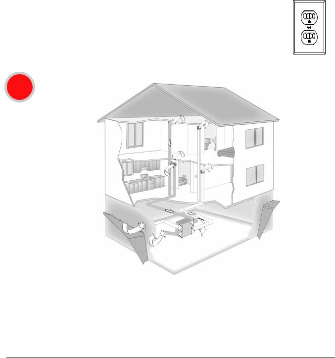
Install to Fit Your Application
NOTE:
AIndependent
10
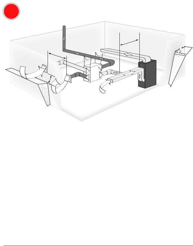
Install to Fit Your Application (continued)
BExhaust at the Source and Supply in the Return
STALE AIR FROM LIVING SPACE,
SUCH AS FROM BATHROOM
OR KITCHEN
TO LIVING
SPACE
6 |
FEET |
|
S
18 |
INCHE |
|
HRV / ERV
3FEET
FORCED AIR
SYSTEM
M28984
This application uses a devoted duct system for the exhausting of stale air accumulated in the home. The fresh air is introduced into the return air duct and is distributed through the home by the existing supply air ductwork of the forced air system.
Make sure when using this application that your fresh air duct connection to the forced air system return air duct is at least 3 feet from the forced air system. You should check with your local code or the forced air system’s manufacturer.
The forced air system’s blower does not have to run when the unit is operating, but is recommended for maximum effectiveness.
NOTE: For the minimum distance between the fresh air connection and the forced air system, check with your local building codes and forced air system manufacturer.
NOTE: For dwellings with multiple forced air systems, Honeywell recommends one ERV/HRV unit per system.
NOTE: Refer to the Wiring section (beginning on page 18) for instructions to connect the unit to operate the forced air system with the ERV/HRV unit.
ERV/HRV Ventilation Systems 69-2480EF—01 |
11 |
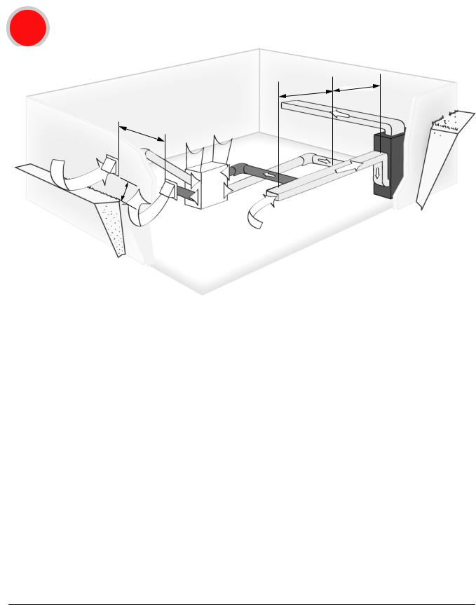
Install to Fit Your Application (continued)
CExhaust and Supply in the Return
3 FEET
6 FEET
TO LIVING SPACE
6 |
FEET |
|
S
18 |
INCHE |
|
FORCED AIR
SYSTEM
HRV / ERV
M28985
When using this application make sure that there is a minimum of 6 feet between the fresh air and exhaust air connections of the ERV/HRV unit in the return air duct. Supply air from the ERV/HRV unit must be at least 3 feet from the forced air system. These distances can be different from one region to another; you should check with your local code or the forced air system’s manufacturer.
NOTE: For minimum distance between return and forced air system, check with your local building codes and forced air system manufacturer.
NOTE: Fresh air must always be down-stream from the exhaust air in the return air duct of the forced air system.
NOTE: Furnace blower is required to operate when ventilation is required. Set the furnace blower to run continuously, or interlock electrically (low voltage).
12 |
ERV/HRV Ventilation Systems 69-2480EF—01 |
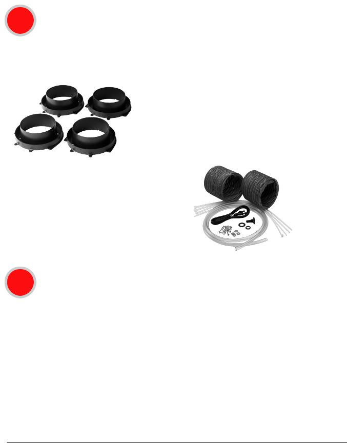
Installation Steps
1Installation Kit
Ensure that you have all of the following installation items:
4 Duct Collars |
Installation Kit: |
|
|
• 2 Flexible 6 in. Vinyl Ducts |
|
|
• 1 Condensation Drain Line (10 in.) |
|
|
• 1 Drain Adapter with Nut |
|
|
• 4 |
Tie Wraps (30 in.) |
|
• 16 Hex-head screws (1/4 x 5/8 in.) |
|
|
• 4 |
Hex-head screws (1/4 x 1 in.) |
|
• 4 |
Washers |
|
• 1 |
Drain cap (VNT5250E100 and VNT5200E1000 only) |
|
• 1 power cord, 120 Vac (not shown) |
|
2Installation Area
The ERV/HRV unit should be installed in a mechanical room or as close to an outside wall as possible.
The ERV/HRV unit must always be installed in an area where the air is conditioned to avoid freezing the condensate line.
The contractor should install the unit in an area that allows the homeowner easy access for maintenance. It is very important to install an electric receptacle (120 Vac) near the unit, a separate circuit breaker
is also recommended. It is best to have access to a condensate drain near the ERV/HRV unit to avoid having to use a condensate pump.
NOTE: Installation is not recommended in unconditioned areas such as an attic or crawl space where the temperature can fall below 32 ºF (0 ºC).
NOTE: Ducting in unconditioned areas must be fully sealed and insulated.
ERV/HRV Ventilation Systems 69-2480EF—01 |
13 |
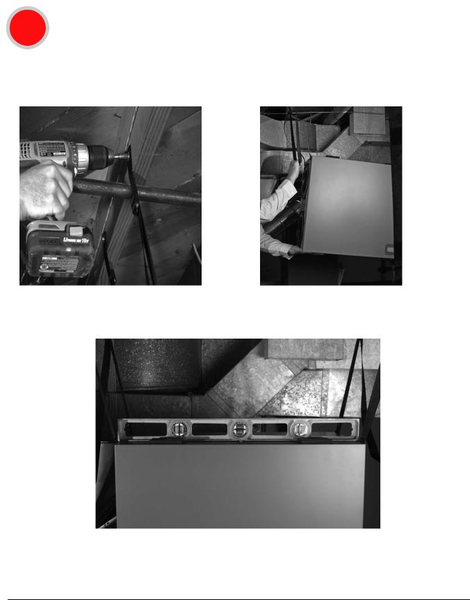
Installation Steps (continued)
3Hanging the ERV/HRV
The ERV/HRV unit enables you to save time and effort by offering a simplified hanging system.
TIP: Removing the core unit makes installation easier since the unit weighs less without the core inside.
1.Attach straps to joist using the supplied washers and four 1 in. hex-head hanging screws.
2.Pull on middle of strap while gently lifting unit upward to raise the unit.
3. Make final adjustments to ensure that the HRV/ERV is level.
NOTE: If the unit is not level, improper drainage will occur and could lead to moisture and leakage problems.
14 |
ERV/HRV Ventilation Systems 69-2480EF—01 |
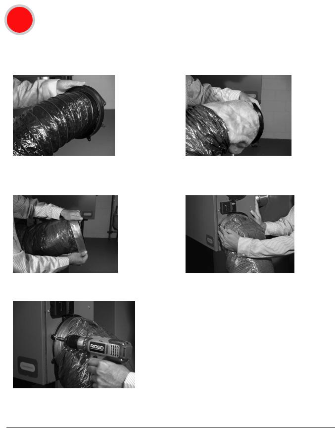
Installation Steps (continued)
4Installing the flex duct to the ERV/HRV
TIP: Honeywell recommends using approximately 16 inches of flexible duct (supplied in kit) between the unit and the rigid duct for noise dampening. The flex duct is mounted to the unit the same way as the insulated flex.
1.Insert the vinyl duct over the hooks on the duct collar and seal with a supplied 30 inch tie wrap.
3. Finish by taping the duct on the collar.
5.Secure collar with the supplied 5/8 in. hex-head screws.
2.Insert insulation inside the outer ring of the duct collar.
4. Slide collar onto unit.
IMPORTANT: Always fix and secure each collar using four of the 5/8 in. screws supplied. This step is critical in order to prevent condensation accumulation.
TIP: Attach the flex duct to the collar first, and then attach the collar to the unit.
ERV/HRV Ventilation Systems 69-2480EF—01 |
15 |
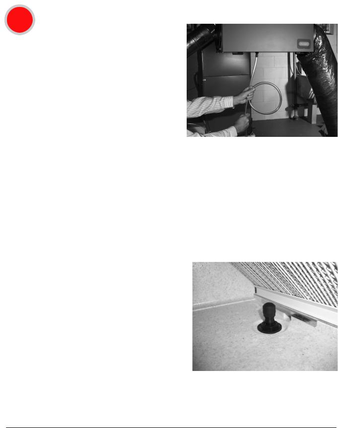
Installation Steps (continued)
5Installing the condensation drain line
Insert the threaded drain adapter through the bottom of the unit and hand tighten the plastic nut supplied with the drain kit.
Use a wrench to tighten the nut another half turn to ensure a complete seal.
Install the condensate tubing by pushing the clear plastic tubing over the drain adapter.
Make a condensate trap by looping the clear plastic tubing. This loop will prevent foul odors from entering the unit.
Use a condensate pump if you don’t have access to the floor drain.
Drainless Application
NOTE: If installing an ERV unit (VNT5150E1000 or VNT5200E1000) in a region where the outdoor temperature does not drop below freezing, the condensate drain line does not need to be installed and the unit may be installed as a drainless application.
1.Insert the threaded drain adapter through the bottom of the ERV with the drain connection inside of the unit as shown in the figure.
2.Fit the rubber washer over the drain adapter and then attach the plastic nut.
3.Hand tighten the plastic nut supplied with the drain kit.
4.Use a wrench to tighten the nut another half turn to ensure a complete seal.
5.Attach the drain cap to the drain adapter inside the unit.
16 |
ERV/HRV Ventilation Systems 69-2480EF—01 |
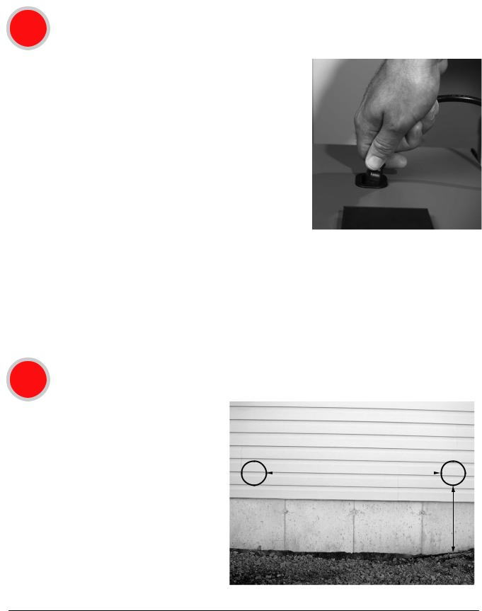
Installation Steps (continued)
6Connecting the power cord
ERV/HRV Power Cord
Insert the power cord on top of the unit. Press firmly to make sure the power cord is secure.
IMPORTANT: Do not plug the power cord into the wall receptacle at this time.
Electric Wall Outlet
Honeywell recommends that the unit has a dedicated receptacle with 120 VAC.
Avoid connecting the unit to the wall receptacle with an extension cord.
Honeywell does not recommend the use of an extension cord. Ensure that the receptacle’s polarization is correct.
NOTE: If the LED light on the ERV/HRV control panel remains green, the motors do not energize, and the controls do not operate; this can indicate that the polarization in the main AC outlet is inverted.
IMPORTANT: Always consult a qualified technician to ensure proper installation of main power.
7Installing outside hoods for the fresh air and the exhaust
Locate the outside hoods at least 18 inches (0.46 m) above grade and at least 72 inches (1.83 m) apart.
NOTE: Do not locate the fresh air vent |
72 (1,829) |
|
|
hood close to known sources of |
|
pollutants such as dryer vents. |
|
18 (457)
IMPORTANT: Always consult your local code for spacing
requirements in your area.
M32372
ERV/HRV Ventilation Systems 69-2480EF—01 |
17 |
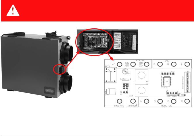
Automated Defrost
The ERV and HRV units are equipped with an automatic defrost feature to eliminate any ice build up on the core.
•Automatic defrost is initiated once every hour when the fresh air supply temperature drops to 23°F (-5°C) or colder.
•The defrost cycle operates by turning off the supply fan while continuing to operate the exhaust fan.
•The exhaust fan speed is adjusted proportionally based on the outdoor temperature, initially operating at low speed.
•As the outdoor temperature continues to drop, the exhaust fan speed will increase, and will operate at maximum speed when the outdoor temperature is -4°F (-20°C) or less.
•Defrost cycle runs for 4 minutes with the supply fan off, followed by 40 minutes of continuous normal operation.
•Defrost cycles will continue to repeat as long as the temperature is 23°F (-5°C) or less.
Wiring
CAUTION: Voltage hazard.
Can cause equipment damage.
Disconnect power from the unit before beginning installation.
Terminal Description
M28986
The wiring terminal block is located behind the control module door on the side of the unit.
To access the terminal block, open the control panel door by swinging it open and to the right as shown above.
18 |
ERV/HRV Ventilation Systems 69-2480EF—01 |
Wiring (continued)
Wiring with Remote Controls
CONT mode - Ventilator runs continuously on low speed. A ventilation call from a control boosts the ventilator into high speed.
INT mode - The ventilator is OFF until a ventilation call from a wall control turns it on in high speed..
Controls Wiring
Follow this diagram if using a Prestige™ 2-wire IAQ and RF EIM.
THM5421R |
R |
(24 VAC) |
|
|
|||
|
TO |
||
|
C |
||
|
THERMOSTAT |
||
|
CONV |
||
|
W |
|
|
|
W2 |
|
|
|
W3 |
|
|
|
Y |
|
|
|
Y2 |
|
|
|
G |
|
|
|
L |
|
|
|
EQUIPMENT |
||
OR |
U3 |
|
|
|
U3 |
|
|
OR |
U3 |
IAQ |
|
U2 |
|||
|
CONTROL |
||
OR |
U1 |
|
|
U1 |
|
||
IAQ DEVICE |
|
||
|
|
||
|
RC |
24 V |
|
|
RH |
POWER |
|
|
|
||
|
R |
|
|
|
C |
|
|
|
S2 |
|
|
|
S2 |
SENSORS |
|
|
S1 |
|
|
S1
SENSOR TYPE |
M28987 |
|
ERV/HRV Ventilation Systems 69-2480EF—01 |
19 |
 Loading...