


UMC800 Controller
Installation and User Guide
Doc. No.: |
51-52-25-61 |
Release: |
F |
Last Revision Date: |
4/01 |
Sensing and Control

Notices and Trademarks
Copyright 2001 by Honeywell
Release F April, 2001
Warranty/Remedy
Honeywell warrants goods of its manufacture as being free of defective materials and faulty workmanship. Contact your local sales office for warranty information. If warranted goods are returned to Honeywell during the period of coverage, Honeywell will repair or replace without charge those items it finds defective. The foregoing is Buyer’s sole remedy and is in lieu of all other warranties, expressed or implied, including those of merchantability and fitness for a particular purpose. Specifications may change without notice. The information we supply is believed to be accurate and reliable as of this printing. However, we assume no responsibility for its use.
While we provide application assistance personally, through our literature and the Honeywell web site, it is up to the customer to determine the suitability of the product in the application.
Sensing and Control
Honeywell
11 West Spring Street
Freeport, Illinois 61032
Honeywell is a U.S. registered trademark of Honeywell
Other brand or product names are trademarks of their respective owners.
ii |
UMC800 Controller Installation and User Guide |
Release F |
|
|
4/01 |

About This Document
Abstract
This document provides descriptions and procedures for the installation, operation and maintenance of the UMC800 Controller hardware.
References
The following list identifies all documents that may be sources of reference for material discussed in this publication.
Document Title |
ID # |
UMC800 Technical Overview Specification |
51-52-03-24 |
UMC800 Operator Interface User Guide |
51-52-25-62 |
UMC800 Control Builder User Guide |
51-52-25-63 |
UMC800 Function Block Reference Guide |
51-52-25-64 |
UMC800 RS232 Communications Reference Manual |
51-52-25-76 |
UMC800 User Utility User’s Guide |
51-52-25-77 |
Modbus® RTU Serial Communications User Manual |
51-52-25-87 |
How to Apply Digital Instrumentation in Severe Electrical Noise Environments |
51-52-05-01 |
Contacts
World Wide Web
The following lists Honeywell’s World Wide Web sites that will be of interest to our customers.
Honeywell Organization |
WWW Address (URL) |
Corporate |
http://www.honeywell.com |
Sensing and Control |
http://www.honeywell.com/sensing |
International |
http://www.honeywell.com/Business/global.asp |
|
|
Telephone
Contact us by telephone at the numbers listed below.
|
Organization |
Phone Number |
|
United States and Canada |
Honeywell |
1-800-423-9883 |
Tech. Support |
|
|
1-888-423-9883 |
Q&A Faxback |
|
|
|
(TACFAQS) |
|
|
1-800-525-7439 Service |
|
Asia Pacific |
Honeywell Asia Pacific |
(852) 2829-8298 |
|
|
Hong Kong |
|
|
Europe |
Honeywell PACE, Brussels, Belgium |
[32-2] 728-2111 |
|
Latin America |
Honeywell, Sunrise, Florida U.S.A. |
(954) 845-2600 |
|
|
|
|
|
Release F |
UMC800 Controller Installation and User Guide |
iii |
4/01 |
|
|
Symbol Definitions
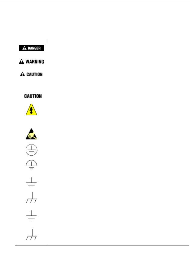
The following table lists those symbols that may be used in this document to denote certain conditions.
Symbol |
Definition |
|
|
This DANGER symbol indicates an imminently hazardous situation, which, if not avoided, will result in death or serious injury.
This WARNING symbol indicates a potentially hazardous situation, which, if not avoided, could result in death or serious injury.
This CAUTION symbol may be present on Control Product instrumentation and literature. If present on a product, the user must consult the appropriate part of the accompanying product literature for more information.
This CAUTION symbol indicates a potentially hazardous situation, which, if not avoided, may result in property damage.
WARNING
PERSONAL INJURY: Risk of electrical shock. This symbol warns the user of a potential shock hazard where HAZARDOUS LIVE voltages greater than 30 Vrms, 42.4 Vpeak, or 60 Vdc may be accessible. Failure to comply with these instructions could result in death or serious injury.
ATTENTION, Electrostatic Discharge (ESD) hazards. Observe precautions for handling electrostatic sensitive devices
Protective Earth (PE) terminal. Provided for connection of the protective earth (green or green/yellow) supply system conductor.
Functional earth terminal. Used for non-safety purposes such as noise immunity improvement. NOTE: This connection shall be bonded to protective earth at the source of supply in accordance with national local electrical code requirements.
Earth Ground. Functional earth connection. NOTE: This connection shall be bonded to Protective earth at the source of supply in accordance with national and local electrical code requirements.
Chassis Ground. Identifies a connection to the chassis or frame of the equipment shall be bonded to Protective Earth at the source of supply in accordance with national and local electrical code requirements.
iv |
UMC800 Controller Installation and User Guide |
Release F |
|
|
4/01 |

Contents |
|
Introduction ............................................................................................. |
1 |
Purpose ........................................................................................................................ |
1 |
UMC800 Controller ...................................................................................................... |
2 |
CE Conformity (Europe)............................................................................................... |
2 |
UMC800 Overview .................................................................................. |
3 |
UMC800 Description .................................................................................................... |
3 |
Feature Summary......................................................................................................... |
4 |
Equipment Identification.......................................................................... |
5 |
Controller Components ................................................................................................ |
5 |
Operator Interface ........................................................................................................ |
7 |
Control Builder.............................................................................................................. |
8 |
Serial Communication Ports....................................................................................... |
10 |
Pre-Installation Considerations ............................................................. |
11 |
Introduction................................................................................................................. |
11 |
Mounting and Wiring ............................................................................. |
15 |
Site Preparation.......................................................................................................... |
15 |
Mounting the Controller.............................................................................................. |
16 |
Plug-in Module Locations........................................................................................... |
18 |
Signal Wiring .............................................................................................................. |
23 |
Wiring Communication Links...................................................................................... |
36 |
Remote Access .......................................................................................................... |
44 |
Power Supply Wiring.................................................................................................. |
51 |
Operation .............................................................................................. |
52 |
Power Up / Power Down ............................................................................................ |
52 |
Operational Modes and Controls ............................................................................... |
53 |
File Downloading........................................................................................................ |
56 |
Code Download.......................................................................................................... |
57 |
Warm Start / Cold Start .............................................................................................. |
58 |
Status Indicators......................................................................................................... |
59 |
RS 485 Port Configuration (Communication Board Option) ...................................... |
61 |
Release F |
UMC800 Controller Installation and User Guide |
v |
4/01 |
|
|

Maintenance ......................................................................................... |
63 |
Overview .................................................................................................................... |
63 |
Routine Maintenance ................................................................................................. |
64 |
Controller Calibration ................................................................................................. |
65 |
Replacement Procedures........................................................................................... |
70 |
Diagnostics and Troubleshooting.......................................................... |
79 |
Overview .................................................................................................................... |
79 |
Controller Diagnostics ................................................................................................ |
79 |
Fault Detection and Troubleclearing .......................................................................... |
81 |
Parts List ............................................................................................... |
91 |
UMC800 Controller .................................................................................................... |
91 |
Specifications........................................................................................ |
93 |
Introduction................................................................................................................. |
93 |
Controller Design........................................................................................................ |
93 |
I/O Module Configuration ........................................................................................... |
93 |
Design ........................................................................................................................ |
97 |
Environmental and Operating Conditions .................................................................. |
99 |
PV Inputs.................................................................................................................. |
100 |
Multilanguage Safety Sheets |
|
Service Centers
vi |
UMC800 Controller Installation and User Guide |
Release F |
|
|
4/01 |

|
Tables |
|
Table 1 |
Controller plug-in I/O module types................................................................................................................ |
6 |
Table 2 |
Communication port descriptions .................................................................................................................. |
10 |
Table 3 |
Operating limits ............................................................................................................................................. |
11 |
Table 4 |
Permissible wiring bundles ............................................................................................................................ |
13 |
Table 5 Power supply input requirements................................................................................................................... |
16 |
|
Table 6 |
I/O module identification............................................................................................................................... |
19 |
Table 7 |
I/O module installation limitations ................................................................................................................ |
20 |
Table 8 |
I/O module identification record.................................................................................................................... |
22 |
Table 9 |
Universal analog input module specifications ............................................................................................... |
25 |
Table 10 |
Summary of communication link connections to controller ........................................................................ |
37 |
Table 11 |
Configuration connector pinouts.................................................................................................................. |
37 |
Table 12 |
Null modem cable construction ................................................................................................................... |
38 |
Table 13 |
Operator interface connector pinouts........................................................................................................... |
40 |
Table 14 Power supply wiring .................................................................................................................................... |
51 |
|
Table 15 Controller mode switch summary ................................................................................................................ |
55 |
|
Table 16 Controller downloading summary ............................................................................................................... |
56 |
|
Table 17 |
Scan rates per inputs configured .................................................................................................................. |
58 |
Table 18 |
Controller status LEDs................................................................................................................................. |
59 |
Table 19 |
Controller status LEDs................................................................................................................................. |
80 |
Table 20 |
Details of the diagnostic summary display .................................................................................................. |
81 |
Table 21 |
Details of the I/O module diagnostics display ............................................................................................. |
87 |
Table 22 |
Controller modem troubleshooting .............................................................................................................. |
89 |
Release F |
UMC800 Controller Installation and User Guide |
vii |
4/01 |
|
|

|
Figures |
|
Figure 1 UMC800 components..................................................................................................................................... |
3 |
|
Figure 2 UMC800 controller hardware......................................................................................................................... |
5 |
|
Figure 3 |
551 operator interface..................................................................................................................................... |
7 |
Figure 4 |
552 operator interface..................................................................................................................................... |
7 |
Figure 5 |
1041 operator interface................................................................................................................................... |
7 |
Figure 6 |
Typical Control Builder graphic display ........................................................................................................ |
8 |
Figure 7 |
UMC800 controller enclosure ...................................................................................................................... |
15 |
Figure 8 |
UMC800 controller enclosure dimensions ................................................................................................... |
17 |
Figure 9 |
UMC800 controller plug-in slots.................................................................................................................. |
18 |
Figure 10 I/O module PWA and terminal ................................................................................................................... |
19 |
|
Figure 11 |
I/O module terminal block (all except 16 point DI) ................................................................................... |
23 |
Figure 12 |
Field wiring shield termination................................................................................................................... |
24 |
Figure 13 |
AI module terminal block connections....................................................................................................... |
25 |
Figure 14 Recommended wiring for one pH sensor input .......................................................................................... |
26 |
|
Figure 15 |
AO module terminal block connections ..................................................................................................... |
27 |
Figure 16 |
DI module terminal block connections....................................................................................................... |
29 |
Figure 17 |
DO module terminal block connections ..................................................................................................... |
30 |
Figure 18 |
DO module relay contact setting ................................................................................................................ |
31 |
Figure 19 PI/FI module terminal block connections.................................................................................................... |
32 |
|
Figure 20 |
PI/FI Module Input Filter Cutoff Frequency setting................................................................................... |
33 |
Figure 21 Pulse / Frequency Input Connections .......................................................................................................... |
33 |
|
Figure 22 Pulse / Frequency card digital output connections ...................................................................................... |
35 |
|
Figure 23 |
Communication port connectors................................................................................................................. |
36 |
Figure 24 |
Ferrite clamp installation ............................................................................................................................ |
39 |
Figure 25 |
Terminal connections ................................................................................................................................. |
41 |
Figure 26 COMM A and B port wiring (2-wire and 4-wire) ...................................................................................... |
42 |
|
Figure 27 |
RS 485 port wiring (2 wire)........................................................................................................................ |
43 |
Figure 28 |
Power supply terminal connections ............................................................................................................ |
51 |
Figure 29 |
Controller mode switch location................................................................................................................. |
54 |
Figure 30 |
Controller status LEDs ............................................................................................................................... |
60 |
Figure 31 COMM A and B ports on CPU module...................................................................................................... |
61 |
|
Figure 32 |
Controller components that contain calibration values............................................................................... |
66 |
Figure 33 |
AI module terminal block........................................................................................................................... |
68 |
Figure 34 AO module jumper ST1 ............................................................................................................................. |
69 |
|
Figure 35 |
Controller components and location........................................................................................................... |
70 |
Figure 36 |
Power supply fuse and CPU battery location ............................................................................................. |
72 |
Figure 37 |
I/O module terminal blocks (not shown: 16 point DI)................................................................................ |
75 |
viii |
UMC800 Controller Installation and User Guide |
Release F |
|
|
4/01 |

Introduction
Purpose
Introduction
Purpose
This Installation and User guide assists in the installation, start up, operation, maintenance and troubleshooting of the UMC800 Controller.
The information in this guide is organized as follows:
Topic
UMC800 Overview
Equipment Identification
Pre-installation
Considerations
Mounting and Wiring
Installation Checkout and
Power Up
Operation
Maintenance
Diagnostics and
Troubleshooting
Parts List
Specifications
Supplemental Installation
Information
Description
Provides a concise description of the UMC800 control system, its applications, architecture and its features
A high-level physical and functional description of the UMC800 components
Lists a number of things to consider when planning the controller installation. Environmental factors as well as methods to minimize interference are discussed.
Information and procedures to successfully install the UMC800 controller and its components. Interconnecting wiring to other UMC800 components is also covered.
Provides a checklist to complete before power up. Covers power up procedure.
Power up and power down routines, operational modes and controls, software download routines, warm and cold start routines, Status LEDs, and scan rates are covered in this section.
Procedures are given covering routine maintenance and the replacement of controller components. Information on I/O module calibration is presented.
Provides description of controller status and error conditions. Provides corrective actions necessary to clear fault conditions.
A list of replacement parts for the controller.
Summary of electrical, physical, environmental and performance specifications.
Provides helpful information for installing digital equipment in severe electrical noise environments.
Refer to document 51-52-05-01 How to Apply Digital Instrumentation in Severe Electrical Noise Environments.
Page
3
5
11
15
44
52
63
79
91
93
––
Release F |
UMC800 Controller Installation and User Guide |
1 |
4/01 |
|
|

Introduction
UMC800 Controller
UMC800 Controller
The UMC800 is industrial process control equipment that must be mounted. The wiring terminals must be enclosed within a panel.
CE Conformity (Europe)
This product is in conformity with the protection requirements of the following European Council Directives: 73/23/EEC, the Low Voltage Directive, and 89/336/EEC, the EMC Directive. Conformity of this product with any other “CE Mark” Directive(s) shall not be assumed.
Deviation from the installation conditions specified in this manual, and the following special conditions, may invalidate this product’s conformity with the Low Voltage and EMC Directives.
ATTENTION
The emission limits of EN 50081-2 are designed to provide reasonable protection against harmful interference when this equipment is operated in an industrial environment. Operation of this equipment in a residential area may cause harmful interference. This equipment generates, uses, and can radiate radio frequency energy and may cause interference to radio and television reception when the equipment is used closer than 30 meters (98 feet) to the antenna(e). In special cases, when highly susceptible apparatus is used in close proximity, the user may have to employ additional mitigating measures to further reduce the electromagnetic emissions of this equipment.
2 |
UMC800 Controller Installation and User Guide |
Release F |
|
|
4/01 |
UMC800 Overview
UMC800 Description
UMC800 Overview
UMC800 Description
The Universal Multiloop Controller (UMC800) is a modular controller designed to address the analog and digital control requirements of small unit processes. With up to 16 analog control loops, four setpoint programmers, and an extensive assortment of analog and digital control algorithms, the UMC800 is an ideal control solution for furnaces, environmental chambers, ovens, reactors, cookers, freeze dryers, extruders, and other processes with similar control requirements.
Accommodating up to 64 universal analog inputs, 16 analog outputs, and 96 digital inputs/outputs, the UMC800 provides the appropriate balance of input and output hardware for these smaller unit processes.
The UMC800 uses separate hardware for control functions and operator interface functions to provide greater installation flexibility. See Figure 1. The controller incorporates card slots capable of supporting up to 16 input and output modules that can be mixed to satisfy the hardware requirements of a specific application. The operator interface uses a color graphic LCD display to provide a variety of display presentations for viewing control loops, setpoint programs, and other analog and digital status.
UMC800
Controller
|
|
|
|
ON |
|
|
|
|
CONFIGURATI |
adir an T L510 1/S |
bat ter y m ay |
expl osi o n. |
truct ions. |
|
atte ry with T |
of a noth er |
ri sk of fire or |
gu ide f or ins |
|
Repla ce b |
only . Use |
prese nt a |
See us ers |
LAY |
|
|
|
|
DISP |
|
|
|
|
A |
|
|
|
|
COMM |
|
|
|
|
COMM B |
_
100230V ~
50/ 60 Hz
100VAMAX. F 3,15 AT
 L1
L1
L2/
N
PC or Laptop with Control Builder Configuration Software, On-Line Help and User Utility Software
RS 485 Serial Communications with Modbus RTU Protocol (Optional)
To Field |
|
|
Operator Interface |
||
Devices |
|
|
Figure 1 UMC800 components
A separate “Control Builder” configuration software program is used for system configuration that operates on a Windows 95or NT-based PC. The software program uses graphic symbols and line drawing connections to create custom control strategies. Menus are provided in the software to allow selection of screens for the operator interface and to customize screen access methods and operator keys. Completed configurations are loaded into the control system using a dedicated communications port in the controller, or optionally, via floppy disk. A separate User Utility software program (also running on a PC) is used to create, edit, save, open and download individual recipe, profile and data storage files. Calibration of the analog input and output modules can be performed through this utility program. A modem connection
Release F |
UMC800 Controller Installation and User Guide |
3 |
4/01 |
|
|

UMC800 Overview
Feature Summary
through the Configuration port allows remote access to the controller via the Control Builder and User Utility programs. This will enable trouble shooting, configuration changes and firmware upgrade.
The optional communications board adds two bi-directional, multi-drop RS 485 serial communication interfaces to the controller CPU module. The COMM A port uses Modbus RTU protocol and is a master/slave link allowing up to 31 controllers to be connected to a single host computer. The computer initiates all communication. COMM B port allows the controller to operate as a master device to up to 16 slave Modbus compatible devices. Data transferred through this port is integrated into the user’s control strategy through read and write function blocks. Applications might include writing controller data (set points, process variables, etc.) to a strip chart recorder to produce a hard copy of process performance, or to read data from other controllers.
Feature Summary
•Up to 16 control loops, including:
−Proportional Integral Derivative (PID),
−ON/OFF,
−Three Position Step Control (TPSC), and
−Carbon Potential.
•Auto-tuning for each control loop
•Up to 64 Universal Analog Inputs
•Up to 16 Analog Outputs
•Up to 96 Digital Inputs/Outputs
•Up to 50 Recipes with up to 50 variables each
•Up to 4 Setpoint Programmers, 3500 total segments
•Setpoint Profile and Recipe storage, up to 70 programs
•Setpoint Scheduler, 10 stored schedules
•Function Block Graphic Configuration with up to 250 blocks
•Large assortment of algorithms for combination of analog and logic functions
•Extensive Alarm and Event monitoring
•Operator interface with a selection of graphic displays
•Carbon Potential, Dewpoint and Relative Humidity Control
•Optional 3-1/2” floppy disk drive for data archiving, setpoint program and recipe storage
•Universal Power (100 to 240 Vac or Vdc) or 24 VA RH)
•UL, CE, and CSA approved, Y2K compliant C/DC (optional)
•Industrial Operating Range (0 °C to 55 °C, 10 % to 90 %
•UL, CE, and CSA Approved, Y2K compliant
4 |
UMC800 Controller Installation and User Guide |
Release F |
|
|
4/01 |

Equipment Identification
Controller Components
Equipment Identification
Controller Components
Enclosure
The UMC800 controller illustrated in Figure 2 consists of a single metal enclosure that houses the following controller components:
•Power supply module that plugs into the controller common backplane.
•CPU module with two serial communications ports. An optional communications board provides two
RS485 serial communication ports (slave and master) that support Modbus® RTU protocol.
•Backplane assembly capable of supporting up to 16 input or output modules.
•Various types of I/O processing modules that plug into the common backplane.
•Removable terminal blocks that connect the I/O modules with the field wiring.
•Battery back-up power for RAM and real time clock in the event of power interruption.
12 |
12 |
12 |
12 |
12 |
12 |
|
|
11 |
11 |
11 |
11 |
11 |
11 |
|
|
10 |
10 |
10 |
10 |
10 |
10 |
|
|
9 |
9 |
9 |
9 |
9 |
9 |
|
|
8 |
8 |
8 |
8 |
8 |
8 |
|
|
7 |
7 |
7 |
7 |
7 |
7 |
|
|
6 |
6 |
6 |
6 |
6 |
6 |
|
|
5 |
5 |
5 |
5 |
5 |
5 |
|
|
4 |
4 |
4 |
4 |
4 |
4 |
|
|
3 |
3 |
3 |
3 |
3 |
3 |
|
|
2 |
2 |
2 |
2 |
2 |
2 |
|
|
1 |
1 |
1 |
1 |
1 |
1 |
|
|
12 |
12 |
12 |
|
|
12 |
12 |
12 |
11 |
11 |
11 |
|
|
11 |
11 |
11 |
10 |
10 |
10 |
|
|
10 |
10 |
10 |
9 |
9 |
9 |
|
|
9 |
9 |
9 |
8 |
8 |
8 |
|
|
8 |
8 |
8 |
7 |
7 |
7 |
|
|
7 |
7 |
7 |
6 |
6 |
6 |
|
|
6 |
6 |
6 |
5 |
5 |
5 |
|
|
5 |
5 |
5 |
4 |
4 |
4 |
|
|
4 |
4 |
4 |
3 |
3 |
3 |
|
|
3 |
3 |
3 |
2 |
2 |
2 |
|
|
2 |
2 |
2 |
1 |
1 |
1 |
|
|
1 |
1 |
1 |
OFFLINE  RUN
RUN
PROGRAM  CONFIGURATION POWER
LoBAT
FORCE
TL5101/S RUN Tadiran may explosion. instructions. with batteryanother orfire for battery of guide Replace ofUse riska user’s  only. present See DISPLAY
 BAT
BAT 
_
100 - 240 V ~
50 / 60 Hz
100 VA MAX.

 F 3,15 A T
 250V
250V
A |
L1 |
|
M |
||
|
||
COM |
L2 / N |
|
|
||
COMM B |
|
Figure 2 UMC800 controller hardware
Release F |
UMC800 Controller Installation and User Guide |
5 |
4/01 |
|
|

Equipment Identification
Controller Components
I/O modules
Eleven different module types can be installed in the controller to support both analog and digital inputs and outputs of various types and signal levels. The signal type and I/O capacity for each module type is indicated in Table 1.
Table 1 Controller plug-in I/O module types
Module Type
Universal Analog Inputs (AI)
Analog Outputs (AO)
Digital Inputs (DI) - 4 types: AC
DC
Logic
16 point
Digital Outputs (DO) - 4 types: AC
AC
High current outputs
DC
Relay
Pulse Input/Frequency Input
pH Power Module
Signal Types |
Maximum |
I/O per |
Maximum no. |
|
|
I/O |
card |
of cards |
|
|
|
|
|
|
mV, V, mA, T/C, RTD, Ohms |
64 |
4 |
16 |
|
0 mA to 20 mA |
16 |
4 |
4 |
|
100/240 Vac |
|
|
|
|
96 |
6 |
16 |
||
24 Vdc |
|
|
|
|
96 |
6 |
16 |
||
Dry contacts |
|
|
|
|
96 |
6 |
16 |
||
(5 mA - 5 Vdc) |
|
|
|
|
Dry contacts |
|
|
|
|
48 |
16 |
3 |
||
100/240 Vac |
|
|
|
|
96 |
6 |
16 |
||
100/240 Vac |
|
|
|
|
|
|
|
||
With: |
12 |
2 |
12 |
|
2 outputs rated @ 2 A |
||||
|
|
|
||
4 outputs rated @ 0.5 A |
|
|
|
|
24 Vdc |
|
|
|
|
96 |
6 |
16 |
||
SPST normally open (NO) or |
|
|
|
|
60 |
6 |
10 |
||
normally closed (NC) contact. |
|
|
|
|
(User configurable) |
|
|
|
|
24 Vdc |
64 |
4 |
16 |
|
± 15 Vdc |
8 |
4 |
2 |
NOTE: Total combined digital I/O is 96 points.
Control architecture
The UMC800 uses a function block configuration architecture to develop control strategies for both analog and digital operations. A function block may represent a physical input or output, a group of physical inputs or outputs, an internal calculation, or an internal function such as a PID algorithm. More than 70 standard UMC800 function block algorithm types are available for configuring analog and logic functions. Typically, a function block algorithm type may be used any number of times up to the limit of 250 blocks. Some of these with specific limitations are:
•Control loops (i.e., PID, ON/OFF, TPSC, and Carbon potential)—eight or sixteen maximum
•Setpoint programmer and associated support blocks—four maximum
•Setpoint Scheduler and associated support blocks—one maximum
•Time proportioning output blocks—sixteen maximum
•Pushbutton blocks—four maximum
• 4 Selector Switch blocks—four maximum
• Modbus Slave blocks—sixteen maximum
6 |
UMC800 Controller Installation and User Guide |
Release F |
|
|
4/01 |
Equipment Identification
Operator Interface
Operator Interface
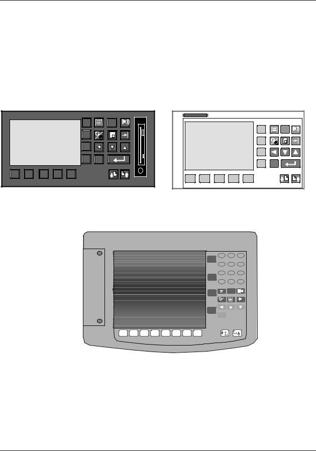
The UMC800 operator interface (Figure 3, Figure 4, and Figure 5) provides a graphic LCD display and a monoplaner keyboard to allow operator access to all controller functions. The operator interface becomes operational once a valid database is configured in the controller. Modification and customization of the operator interface is performed using Control Builder software. With the software, data points can be identified (tagged) using eight character names. Once named, these data points may be accessed by the operator interface using a standard set of display formats and a predefined menu hierarchy. Customized display access and the assignment of selected displays to keyboard buttons may be developed using Control Builder software. Selected displays such as bargraphs, trends, and overview displays will require the user to specify the individual data points to be represented on the display.
|
|
|
|
F1 |
? |
ALARM |
|
|
|
|
F2 |
|
|
|
|
|
|
F3 |
|
|
|
|
|
|
F4 |
ESC |
|
1 |
2 |
3 |
4 |
5 |
|
KB |
|
|
Figure 3 551 operator interface
|
|
|
|
F1 |
? |
ALARM |
|
|
|
|
F2 |
|
|
|
|
|
|
F3 |
|
|
|
|
|
|
F4 |
ESC |
|
1 |
2 |
3 |
4 |
5 |
|
|
Figure 4 552 operator interface
Honeywell
7 8 9
F1
4 5 6
1 2 3
F2
0 . -
?
F3
F4
ESC 
1 |
2 |
3 |
4 |
5 |
6 |
7 |
8 |
|
|
|
|
|
|
||||||||
|
|
|
||||||||
|
|
|
|
|
|
|
|
|
|
|
Figure 5 1041 operator interface
Release F |
UMC800 Controller Installation and User Guide |
7 |
4/01 |
|
|
Equipment Identification
Control Builder
Control Builder
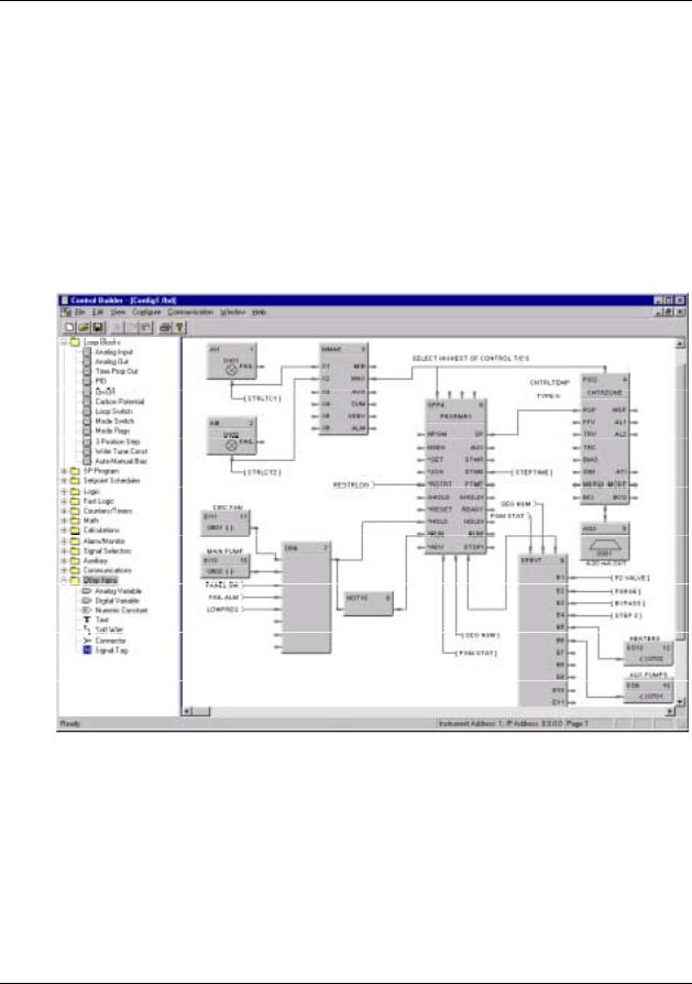
All controller and operator interface configuration is performed using Control Builder software on a separate PC operating with WindowsTM 95 or WindowsTM NT 4.0. All configuration is performed off-line (computer disconnected from the controller and operator interface). The configuration is downloaded in a separate operation as a complete file through a dedicated RS-232 communication port on the controller. Once a configuration is installed into the controller and operator interface, the Control Builder software may be used to monitor areas of the configuration to verify proper operation. Controller configuration development is performed using "Drag and Drop” techniques for positioning graphic icons on a CRT display from a list of available functions. See Figure 6. Signal flow connections from icon to icon complete the controller configuration. The Control Builder software will create a graphic diagram 1 page high by 20 pages wide. The completed diagram may be printed on 20 pages of 8.5" x 11.5" paper. Each configuration is saved as a single PC file. Multiple files may be saved on the PC. The Control Builder can concurrently open multiple configuration files.
Figure 6 Typical Control Builder graphic display
8 |
UMC800 Controller Installation and User Guide |
Release F |
|
|
4/01 |

Equipment Identification
Control Builder
Completed configurations may also be saved on 3.5" floppy disk and loaded into the controller and operator interface through an optional 3.5" floppy disk drive, eliminating the need for a direct connection of a PC to the controller.
Each analog signal flow line of the configuration may be labeled with an 8-character name, 4-character engineering unit definition, and may have a decimal point location specified. Digital signal lines may be identified with an 8-character name and 6-character ON and OFF label.
Signal tag descriptions are used by the operator interface to present on-line status.
Control Builder software may also be used to reconstruct an existing controller configuration by uploading the configuration from the controller for maintenance or diagnostic purposes.
Operator Interface configuration is performed by identifying values to show on predefined display templates and defining the display access buttons.
Control Builder on-line help
The on-line help system provides a convenient and quick way to look up any task you are performing in the Control Builder program. This Windows help system offers context-sensitive help which means that at any time you request help, a help topic appears that pertains to where you are in the program. For example, if you are focused on a particular program window, you will get a help topic that describes that window. If you are in a particular dialog box or entry field, you will get a help topic that describes that dialog box or entry field.
Within a help window there may be hotspots which are shown as highlighted text. If you click on the highlighted text, a pop-up box with a definition or a separate window of information that corresponds to the designated hotspot topic will appear.
The help menu, which is accessible from any main menu, can be used to display an index and the contents of all help topics in the program.
A right-click on a Function Block provides topic help for that block.
User utility
A separate user utility program is available, which is a windows-based program, and is designed for enduser administration tasks of the UMC800. This utility allows you to create, edit, and download recipes, setpoint profiles, setpoint schedules and data storage files. Controller files can be downloaded and uploaded at the PC. Using the communications menu and dialog boxes, communications parameters can be setup to match your PC communications settings. A loopback test can be initiated to verify communications between your PC and the controller, and an error summary provides data for troubleshooting communications problems. The maintenance menu provides access to controller diagnostic data and allows users to initiate calibration of selected I/O modules.
Release F |
UMC800 Controller Installation and User Guide |
9 |
4/01 |
|
|

Equipment Identification
Serial Communication Ports
Serial Communication Ports
The controller contains dedicated serial ports for external communications. These are described in Table 2.
Communication
Port
(on CPU Module)
Configuration
Display
COMM A
(with optional communication board)
COMM B
(with optional communication board)
Table 2 Communication port descriptions
Description
Configuration Port - This RS232 port is a dedicated connection for communications with a PC running the Control Builder configuration program. The communications link layer protocol is proprietary. Communication is through a null modem cable or through a modem.
This RS 422 port is a dedicated connection for communications with the operator interface. Separate power leads included in the cable also supply power to the operator interface. The communications link layer is proprietary and not intended for external use.
RS 485 Serial communication port using Modbus RTU protocol. This port allows the controller to operate as a slave device on a multi-drop bus with up to 31 other UMC800 controllers and Modbus compatible devices. A PC host can be connected to the bus and used for controller configuration and monitoring tasks.
RS 485 Serial communication port using Modbus RTU protocol. This port allows the controller to operate as a master device to up to 16 slave Modbus compatible devices. Data transferred through this port is integrated into the user’s control strategy through read and write function blocks.
10 |
UMC800 Controller Installation and User Guide |
Release F |
|
|
4/01 |

Pre-Installation Considerations
Introduction
Pre-Installation Considerations
Introduction
Installation of the controller consists of mounting and wiring the controller according to the guidelines given in this section. The controller is industrial control equipment that must be panel mounted within an enclosure. The wiring terminals must be enclosed within the enclosure.
Read the pre-installation information, check the model number interpretation [Controller model number (page 21)], and become familiar with your model selections, then proceed with installation.
While the UMC800 has been designed for use in most industrial environments, there are certain requirements that should be considered regarding installation and wiring to ensure optimum performance. Many of the problems associated with electronic control equipment can be traced to the primary ac power system. Disturbance, such as electrical noise, power interruptions, and lightning, must be factored into the planning of the primary power system so the control equipment will perform satisfactorily and continuously.
In addition to the precaution of the separation of signal and power wiring in separate conduits, this section suggests some other measures that can be taken to minimize the effects of electromagnetic interference (EMI) and radio frequency interference (RFI), voltage surges and static electricity.
Operating limits
We recommend that you review and adhere to the operating limits listed in Table 3 when you install the controller.
Table 3 Operating limits
Condition
Ambient Temperature
Relative Humidity
Vibration
Frequency
Acceleration
Mechanical Shock
Acceleration
Duration
Power
Voltage
Frequency (Hz)
Power Consumption
Specifications
32 °F to 131 °F (0 °C to 55 °C)
10 % to 90 % RH at 40 °C (104 °F)
14 Hz to 250 Hz
1 g
1 g
30 ms
100 V to 240 V (24 V optional) 50/60 Hz or dc
100 VA Maximum
Release F |
UMC800 Controller Installation and User Guide |
11 |
4/01 |
|
|

Pre-Installation Considerations
Introduction
Electrical considerations
The controller is considered “open equipment” per EN 61010-1, Safety Requirements for Electrical Equipment for Measurement, Control, and Laboratory Use, Part 1: General Requirements. Conformity with 72/23/EEC, the Low Voltage Directive requires the user to provide adequate protection against a shock hazard. The user shall install this controller in an enclosure that limits OPERATOR access to the rear terminals.
Controller grounding
PROTECTIVE BONDING (grounding) of this controller and the enclosure in which it is installed shall be in accordance with National Electrical Code (ANSI/NFPA 70) and local electrical codes.
Taking electrical noise precautions
Electrical noise is composed of unabated electrical signals that produce undesirable effects in measurements and control circuits.
Digital equipment is especially sensitive to the effects of electrical noise. You should use the following methods to reduce these effects:
•Supplementary bonding of the controller enclosure to a local ground, using a No. 12 (4 mm2) copper conductor, is recommended. This may help minimize electrical noise and transients that may adversely affect the system.
•Separate External Wiring - separate connecting wires into bundles (see Table 4) and route the individual bundles through separate conduits or metal trays.
•Use shielded twisted pair cables for all Analog I/O, Process Variable, RTD, Thermocouple, dc millivolt, low level signal, 4-20 mA, Digital I/O, and computer interface circuits.
•Use suppression devices for additional noise protection. You may want to add suppression devices at the external source. Appropriate suppression devices are commercially available.
•Refer to document 51-52-05-01 How to Apply Digital Instrumentation in Severe Electrical Noise Environments for additional installation guidance.
12 |
UMC800 Controller Installation and User Guide |
Release F |
|
|
4/01 |
Pre-Installation Considerations
Introduction
Permissible wire bundling
Table 4 shows which wire functions should be bundled together.
Table 4 Permissible wiring bundles
Bundle No.
1
Wire Functions
•Line power wiring
•Earth ground wiring
•Control relay output wiring
•Line voltage alarm wiring
2Analog signal wire, such as:
•Input signal wire (thermocouple, 4 mA to 20 mA, etc.)
•4-20 mA output signal wiring
•Slidewire feedback circuit wiring
•Digital input signals
•Communications
3• Low voltage alarm relay output wiring
•Low voltage wiring to solid state type control circuits
Release F |
UMC800 Controller Installation and User Guide |
13 |
4/01 |
|
|

Pre-Installation Considerations
Introduction
14 |
UMC800 Controller Installation and User Guide |
Release F |
|
|
4/01 |
Mounting and Wiring
Site Preparation
Mounting and Wiring
Site Preparation
The UMC800 must be mounted within an enclosure. Hardware is provided to surface mount the controller to a panel or other suitable surface. Be sure that there is sufficient clearance for mounting the controller enclosure and the external wiring.
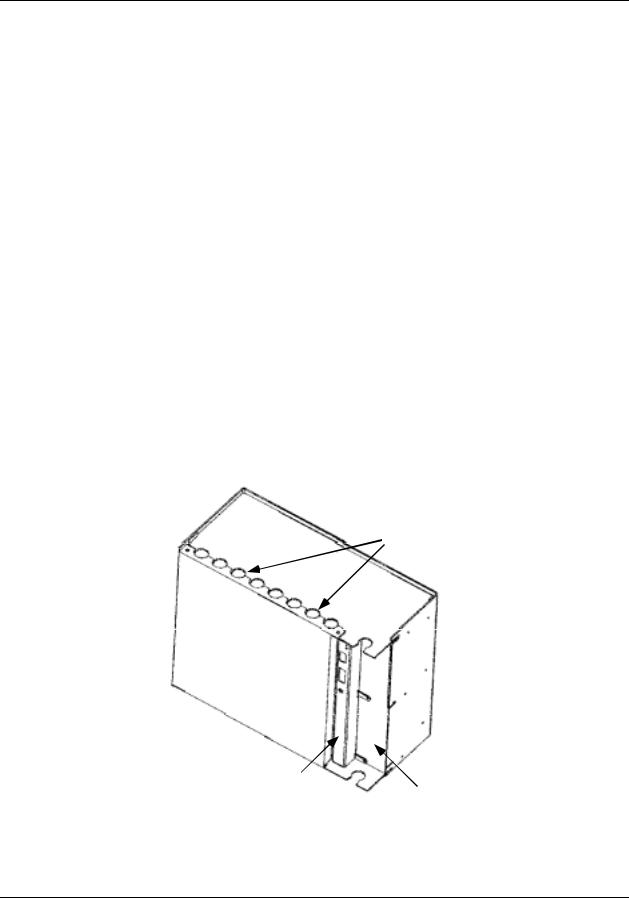
UMC enclosure and components
The controller enclosure houses all circuit assemblies of the UMC controller. See Figure 7. The power supply and CPU are modules that plug into slots on the right hand side of the enclosure. Both modules have metal covers on the front where indicators, switches and connectors are located. All external connections to the power supply and CPU are made on the front panels of these modules.
A front cover can be removed by two screws to access the I/O modules. There are two rows of card guides to accommodate up to 16 plug-in I/O modules. External signal wiring to field devices are made with removable terminal blocks that attach to the front of each I/O module. Optional terminal strips can be used to provide shield termination of field wiring.
Power supply, CPU and I/O modules are connected through a common backplane within the enclosure. All external wiring for power supply and I/O modules are brought out through rubber grommets located at the top and bottom of the enclosure. The CPU features two connections for external communications. One provides a cable connection to a PC for configuration and database file management; the other connection accommodates a cable to the operator interface. An optional communication board provides two RS 485 serial communications ports (slave and master) using Modbus RTU protocol.
External Wiring
Access Holes
Front
Cover
CPU Module
Power Supply
Figure 7 UMC800 controller enclosure
Release F |
UMC800 Controller Installation and User Guide |
15 |
4/01 |
|
|

Mounting and Wiring
Mounting the Controller
Power requirements
The standard supply uses 100/240 Vac or Vdc input ranges for its source. The input requirements are listed in Table 5. Instructions for wiring the power supply are found in Table 5.
Table 5 Power supply input requirements
|
Voltage Input |
Frequency |
Power Consumption |
|
|
|
|
100-240 Vac or dc (+10 % or –15 %) |
50/60 Hz or dc |
100 VA maximum |
|
|
|
|
|
24 |
Vac or dc (optional) |
|
|
24 |
Vac (+25 % or –15 %) or |
50/60 Hz or dc |
100 VA maximum |
24 |
Vdc (+50 % or –8% ) |
|
|
|
|
|
|
Assembling parts
Assemble all parts of the UMC800 along with tools required to mount the UMC800 hardware. You should have these tools on hand:
•Tool box that includes a center punch and a standard complement of flat blade and Phillips head screwdrivers as well as box-end and open-end wrenches.
•A drill tap and drill with number 9 drill bit for drilling clearance holes as applicable.
•Tools for measuring and marking location of clearance holes and cutout on panel as well as cutting a hole in the panel.
Mounting the Controller
Mounting controller enclosure on a panel
The controller enclosure is made to be surface mounted within an enclosure. The controller can be mounted so that the power supply is at the righthand side, or the controller can be rotated 90 degrees so that the power supply is at the top. For either mounting, there must be sufficient space allowed for routing the external wiring.
Four holes at the back of the enclosure are provided for surface mounting with screws. Use the steps in the table below to mount the controller enclosure on a panel.
Step |
Action |
|
|
1Layout mounting hole patterns on panel according to dimensions shown in Figure 8. Or, position controller enclosure on panel and use enclosure as a template.
NOTE: Rotate the mounting dimensions 90 degrees to mount the enclosure sideways with the power supply at the top.
2Drill and tap mounting holes for 1/4-20 (or M6) machine screws (supplied by user).
3Position enclosure on panel so holes in enclosure align with holes in panel. Secure enclosure to panel with 1/4-20 (or M6) machine screws using external tooth washers.
16 |
UMC800 Controller Installation and User Guide |
Release F |
|
|
4/01 |
Mounting and Wiring
Mounting the Controller
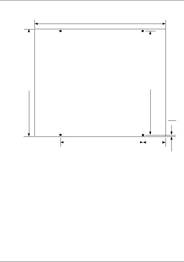
Enclosure mounting dimensions
13.027
330.89
|
|
|
inches |
|
|
|
|
|
|
|
|
|
|
|
|
|
11.77 |
11.37 |
|
||||
Dimensions = _________ |
|
||||||
|
|
|
|
||||
286.26 |
|
||||||
298.96 |
millimeters |
|
|||||
|
|
|
|
||||
|
|
|
|
|
|
|
|
|
|
|
|
|
|
|
|
0.25
6.35
7.0 |
|
|
3.013 |
177.8 |
|
76.53 |
|
NOTE: Allow 7.0” (178 mm) depth to mounting dimensions for controller enclosure and cabling. To mount the controller so that the power supply is at the top, rotate the mounting dimensions 90 degrees.
Figure 8 UMC800 controller enclosure dimensions
Release F |
UMC800 Controller Installation and User Guide |
17 |
4/01 |
|
|
Mounting and Wiring
Plug-in Module Locations
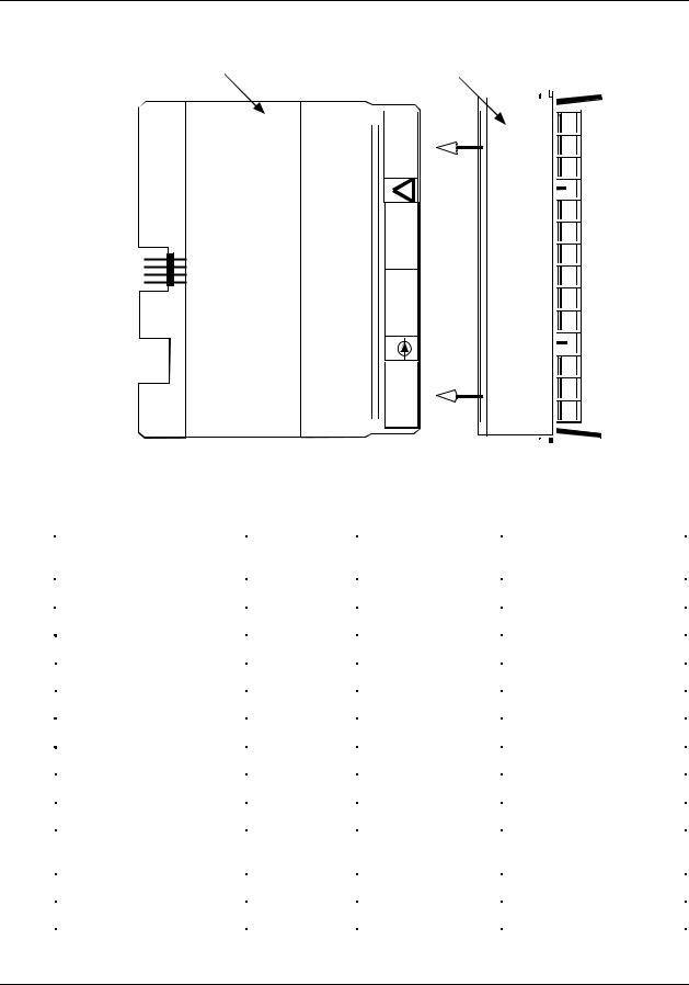
Plug-in Module Locations
Common backplane
The controller backplane provides common connections for the power supply, CPU and I/O modules. All modules are installed into the backplane in their assigned slots designated by the controller model number. [See Controller model number (page 21).] The power supply and CPU occupy the slots on the right side of the enclosure. See Figure 9. Slots for the I/O modules are numbered from 1 to 16 to be consistent with I/O address assignment when using the PC control builder software.
Slots 1-8 (left to right) comprise the lower slots.
Slots 9-16 (left to right) comprise the upper slots.
9 |
10 |
11 |
12 |
13 |
14 |
15 |
16 |
|
|
|
|
|
|
|
|
I/O Module Slots
CPU Power
Supply
1 |
2 |
3 |
4 |
5 |
6 |
7 |
8 |
|
|
|
|
|
|
|
|
Figure 9 UMC800 controller plug-in slots
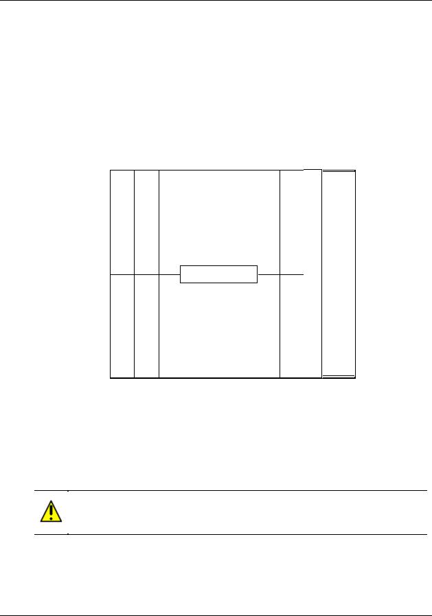
I/O module identification
I/O modules consist of a Printed Wiring Assembly (PWA) and a color-coded terminal block. Each module type is identified by a number label attached to a colored terminal block. Typically, red terminal blocks indicate AC voltage inputs and outputs and black terminal blocks indicate low voltage modules. See Figure 10 for an example. Module type and terminal block identification are described in Table 6.
CAUTION
Do not switch the terminal boards and I/O module PWAs. The color and number designation of the terminal boards should match the correct I/O module type.
18 |
UMC800 Controller Installation and User Guide |
Release F |
|
|
4/01 |
Mounting and Wiring
Plug-in Module Locations
I/O Module |
Terminal |
|
|
PWA |
|
||
Block |
|
||
|
|
||
|
|
|
|
+
OUT4
_
!
+
OUT3
_
+
OUT2
_
0-20mA
+
OUT1
_
Figure 10 I/O module PWA and terminal
Table 6 I/O module identification
Module Type |
|
ID Number |
Terminal Block |
Part Number |
|
|
|
Color |
|
|
|
|
|
|
Analog Input (AI) |
1 |
Black |
46190305-503 |
|
|
|
|
|
|
Analog Output (AO) |
2 |
Black |
46190314-503 |
|
|
|
|
|
|
Digital Input (DI) - Logic |
3 |
Black |
46190311-503 |
|
|
|
|
|
|
Digital Input (DI) - DC |
4 |
Black |
46190347-501 |
|
|
|
|
|
|
Digital Input (DI) - AC |
5 |
Red |
46190350-501 |
|
|
|
|
|
|
Digital Input (DI) - 16 point |
|
B |
Orange or Beige |
46190353-501 |
|
|
|
|
|
Digital Outputs (DO) - Relay |
6 |
Red |
46190308-503 |
|
|
|
|
|
|
Digital Outputs (DO) - DC |
7 |
Black |
46190341-501 |
|
|
|
|
|
|
Digital Outputs (DO) - AC |
8 |
Red |
46190344-501 |
|
|
|
|
|
|
Digital Outputs (DO) - Higher |
|
A |
Red |
46190344-502 |
Current AC |
|
|
|
|
|
|
|
|
|
± 15 Vdc pH Power Module |
|
C |
Black |
51450921-501 |
|
|
|
|
|
Pulse/Frequency Input |
|
D |
Black |
46190360-501 |
|
|
|
|
|
Release F |
UMC800 Controller Installation and User Guide |
19 |
4/01 |
|
|

Mounting and Wiring
Plug-in Module Locations
I/O module limits
The controller backplane accommodates I/O module types, subject to the limitations as shown in Table 7. Slot Locations identify the allowable locations in the controller for each I/O module type. Maximum Allowed describes the maximum I/O configuration for each I/O type in a controller.
Table 7 I/O module installation limitations
I/O Module Type |
Slot Locations |
Maximum Allowed |
|
(See Figure 9) |
|
|
|
|
Universal Analog Input (ID: 1) |
1 through 16 |
16 modules (64 points) |
|
|
|
Analog Output (ID: 2) |
1 through 10 |
4 modules (16 points) |
|
|
|
Digital Input (ID: 3,4,5) |
1 through 16 |
16 modules (96 points)* |
|
|
|
Digital Input 16 point (ID: B) |
14 through 16 |
3 modules (48 points)* |
|
|
|
Digital Output (ID: 6,7,8) |
1 through 8 |
8 modules (48 points)* |
|
|
|
Digital Output (ID: A) |
9 through 16 |
2 modules (12 points)* |
|
|
|
± 15 Vdc pH Power Module (ID: C) |
5, 6 |
2 modules (8 points) |
|
|
|
Pulse/Frequency Input (ID: D) |
1 through 16 |
16 modules (64 points) |
|
|
|
NOTE: Total combined I/O of all types is limited by the 16 available controller I/O slots.
* Total of 96 DI/DOs allowed for all types combined.
20 |
UMC800 Controller Installation and User Guide |
Release F |
|
|
4/01 |

Mounting and Wiring
Plug-in Module Locations
Controller model number
The controller model number specified on your purchase order indicates the I/O module types and the assigned slot location of each I/O module present in the controller. The number fields that identify I/O modules are defined below.
Example of controller model number
Controller Model Number |
8001 - 000 - 0E - 01122300 - 56800000 |
||
I/O module types and controller |
|
|
|
|
|
||
locations for . . . |
Slots 1 to 8 |
Slots 9 to 16 |
|
|
|
|
|
So the number 01122300 - 56800000 indicates that the controller is equipped with I/O module types in the following slot locations:
Controller |
I/O Module Type |
|
|
Controller |
I/O Module Type |
Slot # |
(Module ID) |
|
|
Slot # |
(Module ID) |
|
|
|
|
|
|
1 |
Blank (0) |
|
9 |
DI AC Input (5) |
|
|
|
|
|
|
|
2 |
Analog Input (1) |
|
10 |
DO Relay Output (6) |
|
|
|
|
|
|
|
3 |
Analog Input (1) |
|
11 |
DO AC Output (8) |
|
|
|
|
|
|
|
4 |
Analog Output (2) |
|
12 |
Blank (0) |
|
|
|
|
|
|
|
5 |
Analog Output (2) |
|
13 |
Blank (0) |
|
|
|
|
|
|
|
6 |
DI Logic Input (3) |
|
14 |
Blank (0) |
|
|
|
|
|
|
|
7 |
Blank (0) |
|
15 |
Blank (0) |
|
|
|
|
|
|
|
8 |
Blank (0) |
|
16 |
Blank (0) |
|
|
|
|
|
|
|
NOTE: The numbers (in parenthesis) that identify the I/O module types are defined in Table 6.
Release F |
UMC800 Controller Installation and User Guide |
21 |
4/01 |
|
|
Mounting and Wiring
Plug-in Module Locations
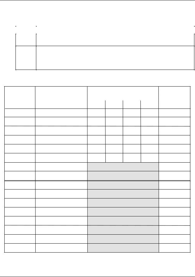
Verify I/O module locations
The table below outlines the steps for identifying and recording the I/O module types in the controller.
Step |
Action |
|
|
1Verify that the module types installed in the controller card slots are correct according to the controller model number. Refer to Table 6 to identify the module types.
2Use to record the location, module type and signal type/range for each I/O module installed in the controller.
NOTE Module types should be installed in accordance with the limitations described in Table 7.
Table 8 I/O module identification record
|
|
Signal Type/Range |
|
|
Controller |
I/O Module Type |
(mV, V, mA, T/C, RTD, Ohms, pH)* |
Terminal Block |
|
Slot No. |
(AI, AO, DI, DO, or PI/FI) |
|
Color |
|
Al Ch 1 Al Ch 2 Al Ch 3 Al Ch 4 |
||||
|
|
|
1
2
3
4
5
6
7
8
9
10
11
12
13
14
15
16
* An Analog Input (AI) Module can be configured to accept multiple input types.
22 |
UMC800 Controller Installation and User Guide |
Release F |
|
|
4/01 |
 Loading...