


 Loading...
UDC2500
Universal Digital Controller
Product Manual
51-52-25-127 April 2007
Honeywell Process Solutions
Industrial Measurement and Control

Notices and Trademarks
Copyright 2007 by Honeywell
Revision 5 April 2007
WARRANTY/REMEDY
Honeywell warrants goods of its manufacture as being free of defective materials and faulty workmanship. Contact your local sales office for warranty information. If warranted goods are returned to Honeywell during the period of coverage, Honeywell will repair or replace without charge those items it finds defective. The foregoing is Buyer's sole remedy and is in lieu of all other warranties, expressed or implied, including those of merchantability and fitness for a particular purpose. Specifications may change without notice. The information we supply is believed to be accurate and reliable as of this printing. However, we assume no responsibility for its use.
While we provide application assistance personally, through our literature and the Honeywell web site, it is up to the customer to determine the suitability of the product in the application.
Honeywell Process Solutions
Industrial Measurement and Control
512 Virginia Drive
Fort Washington, PA 19034
UDC2500 is a U.S. registered trademark of Honeywell
Other brand or product names are trademarks of their respective owners.
4/07 |
UDC2500 Universal Digital Controller Product Manual |
ii |

About This Document
Abstract
This document provides descriptions and procedures for the Installation, Configuration, Operation, and Troubleshooting of your UDC2500 Controller.
Contacts
World Wide Web
The following lists Honeywell’s World Wide Web sites that will be of interest to our customers.
Honeywell Organization |
WWW Address (URL) |
|
|
Corporate |
http://www.honeywell.com |
Industrial Measurement and Control |
http://www.honeywell.com/ps |
Technical tips |
http://content.honeywell.com/ipc/faq |
|
|
Telephone
Contact us by telephone at the numbers listed below.
|
Organization |
Phone Number |
|
|
|
|
|
United States and Canada |
Honeywell |
1-800-423-9883 |
Tech. Support |
|
|
1-800-525-7439 |
Service |
|
|
|
|
4/07 |
UDC2500 Universal Digital Controller Product Manual |
iii |
Introduction
Symbol Definitions
The following table lists those symbols used in this document to denote certain conditions.
Symbol |
Definition |
|
|
This CAUTION symbol on the equipment refers the user to the Product Manual for additional information. This symbol appears next to required information in the manual.
WARNING
PERSONAL INJURY: Risk of electrical shock. This symbol warns the user of a potential shock hazard where HAZARDOUS LIVE voltages greater than 30 Vrms, 42.4 Vpeak, or 60 VDC may be accessible. Failure to comply with these instructions could result in death or serious injury.
ATTENTION, Electrostatic Discharge (ESD) hazards. Observe precautions for handling electrostatic sensitive devices
Protective Earth (PE) terminal. Provided for connection of the protective earth (green or green/yellow) supply system conductor.
Functional earth terminal. Used for non-safety purposes such as noise immunity improvement. NOTE: This connection shall be bonded to protective earth at the source of supply in accordance with national local electrical code requirements.
Earth Ground. Functional earth connection. NOTE: This connection shall be bonded to Protective earth at the source of supply in accordance with national and local electrical code requirements.
Chassis Ground. Identifies a connection to the chassis or frame of the equipment shall be bonded to Protective Earth at the source of supply in accordance with national and local electrical code requirements.
4/07 |
UDC2500 Universal Digital Controller Product Manual |
iv |

|
|
|
Introduction |
|
|
Contents |
|
1 |
INTRODUCTION ................................................................................................... |
1 |
|
1.1 |
|
Overview......................................................................................................................................... |
1 |
1.2 |
|
Function of Displays and Keys ....................................................................................................... |
3 |
1.3 |
|
Process Instrument Explorer Software............................................................................................ |
4 |
1.4 |
|
CE Conformity (Europe)................................................................................................................. |
5 |
2 |
INSTALLATION..................................................................................................... |
7 |
|
2.1 |
|
Overview......................................................................................................................................... |
7 |
2.2 |
|
Condensed Specifications ............................................................................................................... |
8 |
2.3 |
|
Model Number Interpretation ....................................................................................................... |
12 |
2.4 |
|
Control and Alarm Relay Contact Information............................................................................. |
14 |
2.5 |
|
Mounting....................................................................................................................................... |
15 |
2.6 |
|
Wiring ........................................................................................................................................... |
17 |
|
2.6.1 Electrical Considerations ................................................................................................... |
17 |
|
2.7 |
|
Wiring Diagrams........................................................................................................................... |
19 |
3 |
CONFIGURATION............................................................................................... |
32 |
|
3.1 |
|
Overview....................................................................................................................................... |
32 |
3.2 |
|
Configuration Prompt Hierarchy .................................................................................................. |
33 |
3.3 |
|
Configuration Procedure............................................................................................................... |
34 |
3.4 |
|
Tuning Set Up Group.................................................................................................................... |
35 |
3.5 |
|
SP Ramp Set Up Group ................................................................................................................ |
39 |
3.6 |
|
Accutune Set Up Group ................................................................................................................ |
43 |
3.7 |
|
Algorithm Set Up Group............................................................................................................... |
46 |
3.8 |
|
Output Set Up Group .................................................................................................................... |
51 |
3.9 |
|
Input 1 Set Up Group.................................................................................................................... |
55 |
3.10 |
Input 2 Set Up Group ................................................................................................................ |
59 |
|
3.11 |
Control Set Up Group ............................................................................................................... |
61 |
|
3.12 |
Options Group ........................................................................................................................... |
67 |
|
3.13 |
Communications Group ............................................................................................................ |
73 |
|
3.14 |
Alarms Set Up Group ................................................................................................................ |
76 |
|
3.15 |
Display Set Up Group ............................................................................................................... |
82 |
|
3.16 |
P.I.E. Tool Ethernet and Email Configuration Screens............................................................. |
84 |
|
3.17 |
Configuration Record Sheet ...................................................................................................... |
87 |
|
v |
UDC2500 Universal Digital Controller Product Manual |
4/07 |

Introduction
4 |
MONITORING AND OPERATING THE CONTROLLER..................................... |
89 |
||
4.1 |
|
Overview....................................................................................................................................... |
89 |
|
4.2 |
|
Operator Interface ......................................................................................................................... |
90 |
|
4.3 |
Entering a Security Code .............................................................................................................. |
90 |
||
4.4 |
|
Lockout Feature ............................................................................................................................ |
91 |
|
4.5 |
|
Monitoring Your Controller.......................................................................................................... |
93 |
|
|
4.5.1 |
Annunciators ...................................................................................................................... |
93 |
|
|
4.5.2 Viewing the operating parameters...................................................................................... |
94 |
||
|
4.5.3 |
Diagnostic Messages.......................................................................................................... |
95 |
|
4.6 |
|
Single Display Functionality......................................................................................................... |
97 |
|
4.7 |
Start Up Procedure for Operation ................................................................................................. |
99 |
||
4.8 |
|
Control Modes ............................................................................................................................ |
100 |
|
|
4.8.1 |
Mode Definitions ............................................................................................................. |
100 |
|
|
4.8.2 What happens when you change modes........................................................................... |
101 |
||
4.9 |
|
Setpoints...................................................................................................................................... |
101 |
|
4.10 |
Timer ....................................................................................................................................... |
102 |
||
4.11 |
Accutune III............................................................................................................................. |
104 |
||
|
4.11.1 |
Tune for Simplex Outputs ............................................................................................ |
105 |
|
|
4.11.2 |
Tune for Duplex (Heat/Cool) ....................................................................................... |
105 |
|
|
4.11.3 |
Using AUTOMATIC TUNE at start-up for Duplex (Heat/Cool)................................. |
106 |
|
|
4.11.4 |
Using BLENDED TUNE at start-up for Duplex (Heat/Cool)...................................... |
106 |
|
|
4.11.5 |
Using MANUAL TUNE at start-up for Duplex (Heat/Cool)....................................... |
107 |
|
|
4.11.6 |
Error Codes................................................................................................................... |
109 |
|
4.12 |
Fuzzy Overshoot Suppression ................................................................................................. |
110 |
||
4.13 |
Using Two Sets of Tuning Constants...................................................................................... |
110 |
||
4.14 |
Alarm Setpoints....................................................................................................................... |
112 |
||
4.15 |
Three Position Step Control Algorithm................................................................................... |
113 |
||
4.16 |
Setting a Failsafe Output Value for Restart After a Power Loss............................................. |
114 |
||
4.17 |
Setting Failsafe Mode.............................................................................................................. |
115 |
||
4.18 |
Setpoint Rate/Ramp/Program Overview ................................................................................. |
115 |
||
4.19 |
Setpoint Ramp ......................................................................................................................... |
116 |
||
4.20 |
Setpoint Rate ........................................................................................................................... |
117 |
||
4.21 |
Setpoint Ramp/Soak Programming ......................................................................................... |
118 |
||
4.22 |
P.I.E. Tool Maintenance Screens ............................................................................................ |
125 |
||
4.23 |
Configuring your Ethernet Connection ................................................................................... |
131 |
||
5 |
INPUT CALIBRATION....................................................................................... |
136 |
5.1 |
Overview..................................................................................................................................... |
136 |
5.2 |
Minimum and Maximum Range Values ..................................................................................... |
137 |
5.3 |
Preliminary Information.............................................................................................................. |
139 |
5.4 |
Input 1 Set Up Wiring................................................................................................................. |
140 |
4/07 |
UDC2500 Universal Digital Controller Product Manual |
vi |

|
|
|
|
Introduction |
5.5 |
|
Input 1 Calibration Procedure..................................................................................................... |
144 |
|
5.6 |
|
Input 2 Set Up Wiring................................................................................................................. |
146 |
|
5.7 |
|
Input 2 Calibration Procedure..................................................................................................... |
147 |
|
5.8 |
|
Restore Input Factory Calibration............................................................................................... |
149 |
|
6 |
OUTPUT CALIBRATION................................................................................... |
151 |
||
6.1 |
|
Overview..................................................................................................................................... |
151 |
|
6.2 |
|
Current Output Calibration ......................................................................................................... |
152 |
|
6.3 |
|
Auxiliary Output Calibration ...................................................................................................... |
154 |
|
6.4 |
|
Restore Output Factory Calibration Procedure........................................................................... |
156 |
|
7 |
TROUBLESHOOTING/SERVICE...................................................................... |
158 |
||
7.1 |
|
Overview..................................................................................................................................... |
158 |
|
7.2 |
|
Troubleshooting Aids.................................................................................................................. |
159 |
|
7.3 |
|
Power-up Tests............................................................................................................................ |
161 |
|
7.4 |
|
Status Tests ................................................................................................................................. |
161 |
|
7.5 |
|
Background Tests........................................................................................................................ |
162 |
|
7.6 |
|
Controller Failure Symptoms...................................................................................................... |
164 |
|
7.7 |
|
Troubleshooting Procedures ....................................................................................................... |
165 |
|
7.8 |
|
Restoring Factory Configuration ................................................................................................ |
174 |
|
7.9 |
|
Software Upgrades...................................................................................................................... |
175 |
|
8 |
PARTS LIST ...................................................................................................... |
177 |
||
8.1 |
|
Exploded View............................................................................................................................ |
177 |
|
8.2 |
|
Removing the chassis.................................................................................................................. |
179 |
|
9 |
MODBUS RTU FUNCTION CODES.................................................................. |
180 |
||
9.1 |
|
Overview..................................................................................................................................... |
180 |
|
9.2 |
|
General Information.................................................................................................................... |
180 |
|
9.3 |
|
Function Code 20 (14h) - Read Configuration Reference Data.................................................. |
182 |
|
|
9.3.1 |
Read Configuration Examples ......................................................................................... |
184 |
|
9.4 |
|
Function Code 21 (15h) - Write Configuration Reference Data................................................. |
186 |
|
|
9.4.1 |
Write Configuration Examples ........................................................................................ |
188 |
|
10 MODBUS READ, WRITE AND OVERRIDE PARAMETERS PLUS EXCEPTION |
||||
CODES........................................................................................................................ |
|
189 |
||
10.1 |
Overview ................................................................................................................................. |
189 |
||
10.2 |
Reading Control Data.............................................................................................................. |
190 |
||
10.3 Read Software Options Status................................................................................................. |
191 |
|||
10.4 |
Miscellaneous Read Onlys ...................................................................................................... |
192 |
||
vii |
UDC2500 Universal Digital Controller Product Manual |
4/07 |

Introduction
|
10.4.1 |
Register Addresses for Read Onlys .............................................................................. |
192 |
|
|
10.4.2 |
SetPoint Program Read Only Information .................................................................... |
192 |
|
|
10.5 |
Setpoints .................................................................................................................................. |
193 |
|
|
10.6 |
Using a Computer Setpoint (Overriding Controller Setpoint) ................................................ |
194 |
|
|
10.7 |
Configuration Parameters........................................................................................................ |
196 |
|
|
10.7.1 |
Tuning .......................................................................................................................... |
196 |
|
|
10.7.2 |
SP Ramp/Rate/Program ................................................................................................ |
198 |
|
|
10.7.3 |
Accutune ....................................................................................................................... |
201 |
|
|
10.7.4 |
Algorithm ..................................................................................................................... |
202 |
|
|
10.7.5 |
Output Algorithms ........................................................................................................ |
203 |
|
|
10.7.6 |
Input 1 ........................................................................................................................... |
204 |
|
|
10.7.7 |
Input 2 ........................................................................................................................... |
207 |
|
|
10.7.8 |
Control .......................................................................................................................... |
209 |
|
|
10.7.9 |
Options ......................................................................................................................... |
211 |
|
|
10.7.10 |
Communications ........................................................................................................... |
213 |
|
|
10.7.11 |
Alarms .......................................................................................................................... |
214 |
|
|
10.7.12 |
Display .......................................................................................................................... |
217 |
|
|
10.8 |
Modbus RTU Exception Codes............................................................................................... |
218 |
|
11 |
ETHERNET TCP/IP ........................................................................................... |
220 |
||
|
11.1 |
Overview ................................................................................................................................. |
220 |
|
12 |
FURTHER INFORMATION................................................................................ |
221 |
||
|
12.1 |
Modbus RTU Serial Communications .................................................................................... |
221 |
|
|
12.2 |
Modbus Messaging on TCP/IP................................................................................................ |
221 |
|
|
12.3 |
How to Apply Digital Instrumentation in Severe Electrical Noise Environments.................. |
221 |
|
13 |
INDEX |
............................................................................................................... |
222 |
|
14 |
SALES ......................................................................................AND SERVICE |
226 |
||
4/07 |
UDC2500 Universal Digital Controller Product Manual |
viii |

Introduction
Tables
Table 2-1 Condensed Specifications _____________________________________________________ 8 Table 2-2 Control Relay Contact Information _____________________________________________ 14 Table 2-3 Alarm Relay Contact Information ______________________________________________ 14 Table 2-4 Mounting Procedure_________________________________________________________ 16 Table 2-5 Permissible Wiring Bundling__________________________________________________ 18 Table 2-6 Universal Output Functionality and Restrictions___________________________________ 20 Table 2-7 Terminals for connecting a UDC to a MDI Compliant Hub or Switch __________________ 30 Table 2-8 Terminals for connecting a UDC directly to a PC utilizing a straight-through cable ________ 30 Table 3-1 Configuration Topics ________________________________________________________ 32 Table 3-2 Configuration Prompt Hierarchy _______________________________________________ 33 Table 3-3 Configuration Procedure _____________________________________________________ 34 Table 3-4 TUNING Group (Numeric Code 100) Function Prompts ____________________________ 35 Table 3-5 SPRAMP Group (Numeric Code 200) Function Prompts ____________________________ 39 Table 3-6 ATUNE Group (Numeric Code 300) Function Prompts _____________________________ 44 Table 3-7 ALGOR Group (Numeric Code 400) Function Prompts _____________________________ 46 Table 3-8 OUTPUT Group (Numeric Code 500) Function Prompts ____________________________ 51 Table 3-9 INPUT 1 Group (Numeric Code 600) Function Prompts ____________________________ 55 Table 3-10 INPUT2 Group (Numeric Code 700) Function Prompts ____________________________ 59 Table 3-11 Table 3-12 CONTRL Group (Numeric Code 800) Function Prompts _________________ 61 Table 3-13 OPTION Group (Numeric Code 900) Function Prompts ___________________________ 67 Table 3-14 Communications Group (Numeric Code 1000) Function Prompts ____________________ 73 Table 3-15 ALARMS Group (Numeric Code 1100) Function Prompts _________________________ 76 Table 3-16 DISPLY Group (Numeric Code 1200) Function Prompts ___________________________ 82 Table 4-1 Procedure to Enter a Security Code _____________________________________________ 91 Table 4-2 Annunciators ______________________________________________________________ 93 Table 4-3 Lower Display Key Parameter Prompts__________________________________________ 94 Table 4-4 Diagnostic Messages_________________________________________________________ 95 Table 4-5 Single Display Parameters ____________________________________________________ 98 Table 4-6 Procedure for Starting Up the Controller _________________________________________ 99 Table 4-7 Control Mode Definitions ___________________________________________________ 100 Table 4-8 Changing Control Modes (Dual Display Only) ___________________________________ 101 Table 4-9 Procedure for Changing the Local Setpoints _____________________________________ 101 Table 4-10 Procedure for Switching Between Setpoints ____________________________________ 102 Table 4-11 Procedure for Starting “TUNE” ______________________________________________ 105 Table 4-12 Procedure for Using AUTOMATIC TUNE at Start-up for Duplex Control ____________ 106 Table 4-13 Procedure for Using BLENDED TUNE at Start-up for Duplex Control_______________ 107 Table 4-14 Procedure for Using MANUAL TUNE for Heat side of Duplex Control ______________ 107 Table 4-15 Procedure for Using MANUAL TUNE for Cool side of Duplex Control ______________ 108 Table 4-16 Procedure for Accessing Accutune Error Codes _________________________________ 109 Table 4-17 Accutune Error Codes _____________________________________________________ 109 Table 4-18 Set Up Procedure _________________________________________________________ 111 Table 4-19 Procedure for Switching PID SETS from the Keyboard ___________________________ 112 Table 4-20 Procedure for Displaying Alarm Setpoints _____________________________________ 112 Table 4-21 Procedure for Displaying 3Pstep Motor Position_________________________________ 113 Table 4-22 Procedure for Setting a Failsafe Value_________________________________________ 114 Table 4-23 Procedure for Setting a Failsafe Mode_________________________________________ 115 Table 4-24 Running A Setpoint Ramp __________________________________________________ 116 Table 4-25 Program Contents_________________________________________________________ 118
ix |
UDC2500 Universal Digital Controller Product Manual |
4/07 |

Introduction
Table 4-26 Run/Monitor Functions ____________________________________________________ 123 Table 5-1 Voltage, Milliamp and Resistance Equivalents for Input 1 Range Values ______________ 137 Table 5-2 Voltage and Milliamp Equivalents for Input 2 Range Values ________________________ 139 Table 5-3 Equipment Needed_________________________________________________________ 139 Table 5-4 Set Up Wiring Procedure for Thermocouple Inputs Using an Ice Bath ________________ 140 Table 5-5 Set Up Wiring Procedure for Thermocouple Inputs using Thermocouple Source ________ 141 Table 5-6 Set Up Wiring Procedure for RTD Inputs _______________________________________ 141 Table 5-7 Set Up Wiring Procedure for Radiamatic, Millivolts, Volts or Thermocouple Differential Inputs
(Except 0-10 Volts) _____________________________________________________________ 142 Table 5-8 Set Up Wiring Procedure for 0 to 10 Volts ______________________________________ 143 Table 5-9 Set Up Wiring Procedure for Milliampere Inputs _________________________________ 143 Table 5-10 Input 1 Calibration Procedure (Numeric Code 10000) ____________________________ 144 Table 5-11 Set Up Wiring Procedure for 0 to 20 mA or 4 to 20 mA Inputs – Input 2______________ 146 Table 5-12 Set Up Wiring Procedure for 0 to 2 Volts, 0 to 5 Volts, or 1 to 5 Volts – Input 2________ 147 Table 5-13 Input 2 Calibration Procedure (Numeric Code 20000) ____________________________ 148 Table 5-14 Restore Factory Calibration _________________________________________________ 149 Table 6-1 Set Up Wiring Procedure for Current Output ____________________________________ 152 Table 6-2 Current Output Calibration Procedure (Numeric Code 30000) ______________________ 153 Table 6-3 Set Up Wiring Procedure for Auxiliary Output ___________________________________ 154 Table 6-4 Auxiliary Output Calibration Procedure (Numeric Code 50000) _____________________ 155 Table 6-5 Restore Factory Calibration Procedure _________________________________________ 156 Table 7-1 Procedure for Identifying the Software Version __________________________________ 160 Table 7-2 Procedure for Displaying the Status Test (Numeric Code 1200) Results _______________ 161 Table 7-3 Background Tests__________________________________________________________ 162 Table 7-4 Controller Failure Symptoms_________________________________________________ 164 Table 7-5 Troubleshooting Power Failure Symptoms ______________________________________ 166 Table 7-6 Troubleshooting Current Output Failure ________________________________________ 166 Table 7-7 Troubleshooting Three Position Step Control Output Failure ________________________ 167 Table 7-8 Troubleshooting Time Proportional Output Failure _______________________________ 168 Table 7-9 Troubleshooting Current/Time or Time/Current Proportional Output Failure ___________ 169 Table 7-10 Troubleshooting Alarm Relay Output Failure ___________________________________ 170 Table 7-11 Troubleshooting a Keyboard Failure __________________________________________ 171 Table 7-12 Troubleshooting a RS-485 Communications Failure______________________________ 172 Table 7-13 Troubleshooting an Ethernet Communications Failure ____________________________ 173 Table 7-14 Troubleshooting Auxiliary Output Failure _____________________________________ 173 Table 7-15 Restoring Factory Configuration _____________________________________________ 174 Table 7-16 Software Upgrades________________________________________________________ 175 Table 8-1 Parts Identification _________________________________________________________ 178 Table 8-2 Parts Not Shown___________________________________________________________ 178 Table 8-3 Software Upgrades (see Section 7.9) ___________________________________________ 178 Table 9-1 Integer Parameter Type _____________________________________________________ 181 Table 9-2 Floating Point Parameter Type________________________________________________ 181 Table 9-3 Register Address Format for Function Code 20___________________________________ 183 Table 9-4 Register Address Format for Function Code 21___________________________________ 187 Table 10-1 Control Data Parameters ___________________________________________________ 191 Table 10-2 Option Status ____________________________________________________________ 191 Table 10-3 Miscellaneous Read Onlys__________________________________________________ 192 Table 10-4 SetPoint Program Read Only Information ______________________________________ 192 Table 10-5 Setpoint Code Selections ___________________________________________________ 193 Table 10-6 Setpoint Associated Parameters ______________________________________________ 193
4/07 |
UDC2500 Universal Digital Controller Product Manual |
x |
Introduction
Table 10-7 Computer Setpoint Selection ________________________________________________ 194 Table 10-8 Computer Setpoint Associated Parameters _____________________________________ 195 Table 10-9 Set-up Group – Tuning ____________________________________________________ 196 Table 10-10 Set-up Group – Setpoint Ramp/Rate _________________________________________ 198 Table 10-11 Set-up Group – Accutune__________________________________________________ 201 Table 10-12 Set-up Group – Algorithm _________________________________________________ 202 Table 10-13 Set-up Group – Output____________________________________________________ 203 Table 10-14 Set-up Group – Input 1____________________________________________________ 204 Table 10-15 Set-up Group – Input 2____________________________________________________ 207 Table 10-16 Set-up Group – Control ___________________________________________________ 209 Table 10-17 Set-up Group – Options ___________________________________________________ 211 Table 10-18 Set-up Group – Communications____________________________________________ 213 Table 10-19 Set-up Group – Alarms ___________________________________________________ 214 Table 10-20 Set-up Group – Display ___________________________________________________ 217 Table 10-21 Modbus RTU Data Layer Status Exception Codes ______________________________ 219
xi |
UDC2500 Universal Digital Controller Product Manual |
4/07 |

Introduction
Figures
Figure 1-1 UDC2500 Operator Interface (all display items shown) _____________________________ 2 Figure 1-2 Screen capture of Process Instrument Explorer running on a Pocket PC _________________ 4 Figure 1-3 Depiction of infrared communications ___________________________________________ 5 Figure 2-1 Model Number Interpretation _________________________________________________ 13 Figure 2-2 Mounting Dimensions (not to scale)____________________________________________ 15 Figure 2-3 Mounting Methods _________________________________________________________ 16 Figure 2-4 Composite Wiring Diagram __________________________________________________ 21 Figure 2-5 Mains Power Supply________________________________________________________ 22 Figure 2-6 Input 1 Connections ________________________________________________________ 23 Figure 2-7 Input 2 Connections ________________________________________________________ 24 Figure 2-8 Electromechanical Relay Output ______________________________________________ 24 Figure 2-9 Solid State Relay Output ____________________________________________________ 25 Figure 2-10 Open Collector Output _____________________________________________________ 26 Figure 2-11 Dual Electromechanical Relay Option Output ___________________________________ 27 Figure 2-12 Current Output ___________________________________________________________ 27 Figure 2-13 Three Position Step Control Connections w/o Dual Relay Option____________________ 28 Figure 2-14 Three Position Step Control Connections with Dual Relay Option ___________________ 28 Figure 2-15 RS-422/485 Communications Option Connections _______________________________ 29 Figure 2-16 Ethernet Communications Option Connections __________________________________ 29 Figure 2-17 Auxiliary Output and Digital Inputs Option Connections __________________________ 30 Figure 2-18 Transmitter Power for 4-20 mA — 2 wire Transmitter Using Open Collector Alarm 2 Output31 Figure 2-19 Transmitter Power for 4-20 mA — 2 Wire Transmitter Using Auxiliary Output ________ 31 Figure 3-1 Ethernet Configuration Screen ________________________________________________ 84 Figure 3-2 Email Configuration Screen __________________________________________________ 85 Figure 4-1 Operator Interface__________________________________________________________ 90 Figure 4-2 Functional Overview Block Diagram of the UDC2500 Controller ____________________ 96 Figure 4-3 Ramp/Soak Profile Example_________________________________________________ 121 Figure 4-4 Program Record Sheet _____________________________________________________ 122 Figure 4-5 Maintenance Data Menu____________________________________________________ 125 Figure 4-6 Loop Data Maintenance Screen ______________________________________________ 126 Figure 4-7 Alarm Details Maintenance Screen ___________________________________________ 127 Figure 4-8 Digital Input Details Screen _________________________________________________ 128 Figure 4-9 Status Data Maintenance Screen______________________________________________ 129 Figure 4-10 Ethernet Status Maintenance Screen__________________________________________ 130 Figure 4-11 IR Communications Address _______________________________________________ 131 Figure 4-12 Online Configuration _____________________________________________________ 132 Figure 4-13 Configuration Upload in Progress ___________________________________________ 132 Figure 4-14 Ethernet Communications Type Selection _____________________________________ 133 Figure 4-15 Ethernet Communications Address __________________________________________ 134 Figure 4-16 Configuration Upload in Progress ___________________________________________ 135 Figure 5-1 Input 1 and Input 2 Wiring Terminals _________________________________________ 139 Figure 5-2 Wiring Connections for Thermocouple Inputs Using an Ice Bath ____________________ 140 Figure 5-3 Wiring Connections for Thermocouple Inputs Using Thermocouple Source ___________ 141 Figure 5-4 Wiring Connections for RTD (Resistance Thermometer Device) ____________________ 141 Figure 5-5 Wiring Connections for Radiamatic, Thermocouple Differential, Millivolts or Volts (Except 0 to 10
Volts) ________________________________________________________________________ 142 Figure 5-6 Wiring Connections for 0 to 10 Volts__________________________________________ 143 Figure 5-7 Wiring Connections for 0 to 20 mA or 4 to 20 mA Inputs__________________________ 143
4/07 |
UDC2500 Universal Digital Controller Product Manual |
xii |

Introduction
Figure 5-8 Wiring Connections for 0 to 20 mA or 4 to 20 mA Input – Input 2 ___________________ 146 Figure 5-9 Wiring Connections for 0 to 2 Volts, 0 to 5 Volts or 1 to 5 Volts Input – Input 2________ 147 Figure 6-1 Wiring Connections for Calibrating Current Output ______________________________ 152 Figure 6-2 Wiring Connections for Calibrating Auxiliary Output _____________________________ 154 Figure 8-1 UDC2500 Exploded View __________________________________________________ 177 Figure 10-1 Software Option Status Information __________________________________________ 191
xiii |
UDC2500 Universal Digital Controller Product Manual |
4/07 |

Introduction
1 Introduction
1.1 Overview
Function
The UDC2500 is a microprocessor-based stand-alone controller. It combines a high degree of functionality and operating simplicity in a 1/4 DIN size controller. This instrument is an ideal controller for regulating temperature and other process variables in numerous heating and cooling applications, as well as in metal working, food, pharmaceuticals, semiconductor, testing and environmental work.
The UDC2500 monitors and controls temperatures and other variables in applications such as environmental chambers, plastic processing machines, furnaces and ovens, and packaging machinery.
Features
•90 – 264 Vac or 24 Vac/dc Power Supply
•Input/Output Isolation
•Isolated Auxiliary Current Output / Digital Inputs
•Modbus® RS-485, Infrared, or Ethernet TCP/IP Communications
•Infrared interface
•Timer
•Accutune III Tuning with Fuzzy Logic Overshoot Suppression.
•2nd Input (Remote Setpoint)
•Setpoint Ramp/Rate/Program
•Three Position Step Control
•Duplex (Heat/Cool)
Easy to Read Displays
The dedicated vacuum fluorescent displays with multi-language prompts make the operator interface easy to read, understand and operate. Programmed sequences of displays assure quick and accurate entry of all configurable parameters.
Easy to Operate
Simple keystrokes let you select input and range configuration, set the operating parameters that meet you process control needs now, and change them later to meet new ones.
4/07 |
UDC2500 Universal Digital Controller Product Manual |
1 |

Introduction
Mount Anywhere
This instrument is intended for industrial control applications. It must be panel mounted with the wiring terminals enclosed within the panel. The instrument is environmentally hardened and, when suitably enclosed, can be mounted anywhere in plant or factory, on the wall, or even on the process machine itself. The front face is NEMA3 and IP55 rated and can be easily changed to NEMA4X and IP66 for the most severe hose-down applications. It withstands ambient temperatures up to 55°C (133°F) and resists the effects of vibration and shock.
Figure 1-1 UDC2500 Operator Interface (all display items shown)
2 |
UDC2500 Universal Digital Controller Product Manual |
4/07 |
Introduction
1.2 Function of Displays and Keys
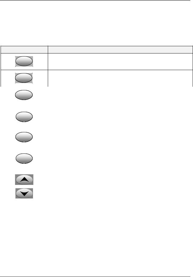
Table 1-1 shows each key on the operator interface and defines its function.
Table 1-1Function of Displays and Keys
Key
Setup
Function
Function
•Places the controller in the Configuration Set Up group select mode. Sequentially displays Set Up groups and allows the FUNCTION key to display individual functions in each Set Up group.
•Used in conjunction with the SET UP key to select the individual functions of a selected Configuration Set Up group.
•Used during field calibration procedure.
|
|
|
• |
Selects an operating parameter to be shown in the lower display. See |
|
|
Lower |
||||
|
|
|
Section 4.5.2 for a list of the operating parameters and Section 4.5.3 for a list |
||
|
Display |
|
|
||
|
|
|
of the diagnostic messages. |
||
|
|
|
|
||
|
|
|
|
||
|
|
|
• Alternately selects: |
||
|
|
|
|
AUTO Lower display automatically displays setpoint value in engineering |
|
|
M-A |
|
|
||
|
|
|
|
units. |
|
|
Reset |
|
|
|
|
|
|
|
MAN |
Lower display automatically indicates output in %. |
|
|
|
|
|
||
|
|
|
|
RESET Only used on Limit Controllers to reset the Limit Relay. |
|
|
|
|
|
|
|
|
|
|
• |
Setpoint Select Hold key down to cycle through configured setpoints. |
|
|
SP |
|
|||
|
Select |
|
|
|
|
|
|
|
|
|
|
|
|
|
• |
Alternate action switch initiates or holds the Setpoint Ramp or Setpoint |
|
|
|
|
|
Program. |
|
|
Run |
|
|
||
|
|
|
|
|
|
|
Hold |
|
• |
Acknowledges a latched alarm 1. |
|
|
|
|
• Acknowledges Diagnostic Messages. |
||
|
|
|
|
|
|
|
|
|
• |
Increases the selected parameter value. |
|
|
|
|
|
|
|
|
|
|
• |
Decreases the selected parameter value. |
|
|
|
|
|
|
|
Note 1: Value can be changed if in manual mode. For Three Position Step Control when a slidewire is not used, the output value is the estimated motor position.
Note 2: Value can be changed via increment/decrement keys.
Note 3: The selected set can be changed via increment/decrement keys.
4/07 |
UDC2500 Universal Digital Controller Product Manual |
3 |
Introduction
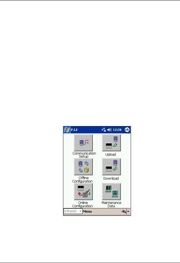
1.3 Process Instrument Explorer Software
Overview
Process Instrument Explorer lets you configure your instrument on a desktop/laptop or Pocket PC. For details see Process Instrument Explorer manual #51-52-25-131.
Features
•Create configurations with intuitive software program running on either a Pocket PC, a Desktop or a laptop computer. ·
•Create/edit configurations live, just connect software to controller via comm port.·
•Create/edit configurations offline and download to controller later via comm. port.·
•Port types available on every UDC2500:·
o Infrared o RS 485
oEthernet
•Same port types on UDC3200 and UDC3500 allow interconnectivity.
•This software is available in English, Spanish, Italian, German and French.
Figure 1-2 Screen capture of Process Instrument Explorer running on a Pocket PC
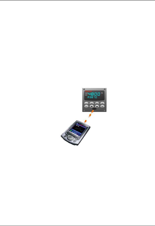
Infrared communications
The infrared connection provides a non-intrusive wireless connection with the instrument and maintains NEMA4X AND IP66 integrity.
4 |
UDC2500 Universal Digital Controller Product Manual |
4/07 |
Introduction
No need to get access to the back of the controller to communicate with the instrument, no need to take your screw driver to wire the communication cable, no wiring mistake possible. You can now duplicate an instrument’s configuration, upload or download a new configuration in a matter of seconds, just by pointing your Pocket PC in the direction of the instrument.
It takes just a few seconds to upload a configuration from an instrument. You can then save the configuration file onto your PC or pocket PC for review, modification or archiving. Furthermore, this software also gives you important maintenance information on the controller: instantly, get information on the current operating parameters, digital inputs and alarm status, identify internal or analog input problems.
Question: What if I have several controllers on the same panel? How can I be sure I am communicating with the correct one?
Answer: The infrared port of the controller is normally “off”. You activate the infrared port by pressing any controller’s key. You can now communicate. After 4 minutes, the port will be shut down again. Also, in the Communications Group “IR ENABLE” may be disabled to prohibit IR communications.
Figure 1-3 Depiction of infrared communications
1.4 CE Conformity (Europe)
This product is in conformity with the protection requirements of the following European Council Directives: 73/23/EEC, the Low Voltage Directive, and 89/336/EEC, the EMC Directive. Conformity of this product with any other “CE Mark” Directive(s) shall not be assumed.
Product Classification: Class I: Permanently connected, panel-mounted Industrial Control Equipment with protective earthing (grounding) (EN61010-1).
Enclosure Rating: This controller must be panel-mounted with the rear terminals enclosed within the panel. The front panel of the controller is rated at NEMA4X and IP66 when properly installed.
Installation Category (Overvoltage Category): Category II (EN61010-1)
4/07 |
UDC2500 Universal Digital Controller Product Manual |
5 |

Introduction
Pollution Degree: Pollution Degree 2: Normally non-conductive pollution with occasional conductivity caused by condensation. (Ref. IEC 664-1)
EMC Classification: Group 1, Class A, ISM Equipment (EN61326, emissions), Industrial Equipment (EN61326, immunity)
Method of EMC Assessment: Technical File (TF) Declaration of Conformity: 51453655
Deviation from the installation conditions specified in this manual, and the special conditions for CE conformity in Subsection 2.1, may invalidate this product’s conformity with the Low Voltage and EMC Directives.
ATTENTION
The emission limits of EN61326 are designed to provide reasonable protection against harmful interference when this equipment is operated in an industrial environment. Operation of this equipment in a residential area may cause harmful interference. This equipment generates, uses, and can radiate radio frequency energy and may cause interference to radio and television reception when the equipment is used closer than 30 meters (98 feet) to the antenna(e). In special cases, when highly susceptible apparatus is used in close proximity, the user may have to employ additional mitigating measures to further reduce the electromagnetic emissions of this equipment.
WARNING
If this equipment is used in a manner not specified by the manufacturer, the protection provided by the equipment may be impaired.
6 |
UDC2500 Universal Digital Controller Product Manual |
4/07 |
Installation
2 Installation
2.1 Overview
Introduction
Installation of the UDC2500 consists of mounting and wiring the controller according to the instructions given in this section. Read the pre-installation information, check the model number interpretation (Subsection 2.3), and become familiar with your model selections, then proceed with installation.
What’s in this section?
The following topics are covered in this section.
|
TOPIC |
See Page |
2.1 |
Overview |
7 |
|
|
|
2.2 |
Condensed Specifications |
8 |
|
|
|
2.3 |
Model Number Interpretation |
12 |
|
|
|
2.4 |
Control and Alarm Relay Contact Information |
14 |
|
|
|
2.5 |
Mounting |
15 |
|
|
|
2.6 |
Wiring |
17 |
|
|
|
2.7 |
Wiring Diagrams |
19 |
|
Composite Wiring Diagram |
21 |
|
AC Line Voltage |
22 |
|
Input 1 Connections |
23 |
|
Input 2 Connections |
24 |
|
Relay Output |
|
|
Electromechanical |
24 |
|
Solid State |
25 |
|
Open Collector |
26 |
|
Dual Electromechanical Relay |
27 |
|
Current Output Connections |
27 |
|
Three Position Step Control Connections w/o Dual Relay |
28 |
|
Three Position Step Control Connections with Dual Relay |
28 |
|
RS-422/485 Communications Option |
29 |
|
Ethernet Communications Option |
29 |
|
Auxiliary Output and Digital Inputs Option |
30 |
|
Transmitter Power using Open Collector Output |
31 |
|
Transmitter Power using Auxiliary Output |
31 |
|
|
|
4/07 |
UDC2500 Universal Digital Controller Product Manual |
7 |

Installation
Pre-installation Information
If the controller has not been removed from its shipping carton, inspect the carton for damage then remove the controller.
•Inspect the unit for any obvious shipping damage and report any damage due to transit to the carrier.
•Make sure a bag containing mounting hardware is included in the carton with the controller.
•Check that the model number shown on the inside of the case agrees with what you have ordered.
2.2Condensed Specifications
Honeywell recommends that you review and adhere to the operating limits listed in Table 2-1 when you install your controller.
Table 2-1 Condensed Specifications
Specifications
Analog Inputs |
Accuracy: |
|
± 0.25% of full scale typical (± 1 digit for display) |
|
Can be field calibrated to ± 0.05% of full scale typical |
|
16-bit resolution typical |
|
Sampling Rate: Both inputs are sampled six times per second |
|
Temperature Stability: ± 0.01% of Full Scale span / ˚C change—typical |
|
Input Impedance: |
|
4-20 Milliampere Input: 250 ohms |
|
0-10 Volt Input: 200K ohms |
|
All Others: 10 megohms |
|
Maximum Lead Wire Resistance: |
|
Thermocouples: 50 ohms/leg |
|
100 ohm, 200 ohm and 500 ohm RTD: 100 ohms/leg |
|
100 ohm Low RTD: 10 ohms/leg |
|
|
Analog Input Signal |
Burnout Selections: Upscale, Downscale, Failsafe or None |
Failure Operation |
Thermocouple Health: Good, Failing, Failure Imminent or Failed |
|
Failsafe Output Level: Configurable 0-100% of Output range |
Stray Rejection |
Common Mode |
|
AC (50 or 60 Hz): 120 dB (with maximum source impedance of 100 ohms) or ± 1 LSB (least |
|
significant bit) whichever is greater with line voltage applied. |
|
DC: 120 dB (with maximum source impedance of 100 ohms) or a ±1 LSB whichever is |
|
greater with 120 Vdc applied. |
|
DC (to 1 KHz): 80 dB (with maximum source of impedance of 100 ohms) or ±1 LSB |
|
whichever is greater with 50 Vac applied. |
|
Normal Mode |
|
AC (50 or 60 Hz): 60 dB (with 100 % span peak-to-peak maximum) |
|
|
Digital Inputs (Two) |
+30 Vdc source for external dry contacts or isolated solid state contacts. Digital Inputs are |
(Optional) |
isolated from line power, earth ground, analog inputs and all outputs except for the Second |
|
Current Output. |
|
The second Digital Input is mutually exclusive with the Second Current Output. |
|
|
8 |
UDC2500 Universal Digital Controller Product Manual |
4/07 |

|
|
Installation |
|
|
|
|
|
|
|
Specifications |
|
Controller Output |
Electromechanical Relays (One or Two) |
|
|
Types |
SPDT contacts. Both Normally Open and Normally Closed contacts are brought out to the |
|
|
|
|
rear terminals. Internally socketed. |
|
|
|
Resistive Load: 5 amps @ 120 Vac or 240 Vac or 30 Vdc |
|
|
|
Inductive Load (cosϕ = 0.4): 3 amps @ 130 Vac or 250 Vac |
|
|
|
Inductive Load (L/R = 7 msec): 3.5 amps @ 30 Vdc |
|
|
|
Motor: 1/6 H.P. |
|
|
|
Dual Electromechanical Relays |
|
|
|
Two SPST contacts. One Normally Closed contact for each relay is brought out to the rear |
|
|
|
terminals. Useful for Time Duplex or Three Position Step control applications, this option |
|
|
|
takes the place of one of the above electromechanical relays, thus saving it for use as an |
|
|
|
alarm. Units with this output option may have two additional relays (total of four relays) plus |
|
|
|
the Second Current Output. Relays are internally socketed. |
|
|
|
Resistive Load: 2 amps @ 120 Vac, 240 Vac or 30 Vdc |
|
|
|
Inductive Load (cosϕ = 0.4): 1 amp @ 130 Vac or 250 Vac |
|
|
|
Inductive Load (L/R = 7 msec): 1 amp @ 30 Vdc |
|
|
|
Solid State Relays (One or Two) |
|
|
|
Zero-crossing type SPST solid state contacts consisting of a triac N.O. output. Internally |
|
|
|
socketed. |
|
|
|
Resistive Load: 1.0 amp @ 25°C and 120 or 240 Vac, 0.5 amp @ 55°C and 120 or 240 Vac |
|
|
|
Inductive Load: 50 VA @ 120 Vac or 240 Vac |
|
|
|
Minimum Load: 20 milliamps |
|
|
|
Open Collector Outputs (One or Two) |
|
|
|
Socketed assembly replacing a relay. Opto-isolated from all other circuits except current |
|
|
|
output and not from each other. Internally powered @ 30 Vdc. |
|
|
|
Note: Applying an external power supply to this output will damage the instrument. |
|
|
|
Maximum Sink Current: 20 mA |
|
|
|
Short-circuit current limit: 100 mA |
|
|
|
Current Outputs (One or Two) |
|
|
|
These outputs provide a 21 mA dc maximum into a negative or positive grounded load or into |
|
|
|
a non-grounded load. Current outputs are isolated from each other, line power, earth ground |
|
|
|
and all inputs. Outputs can be easily configured via the keyboard for either direct or reverse |
|
|
|
action and for either 0 to 20 mA or 4 to 20 mA without field calibration. |
|
|
|
The second current output can be used in an Auxiliary Output mode. This Auxiliary Output |
|
|
|
can be configured to represent either Input, PV, Setpoint, Deviation, or Control output. The |
|
|
|
range of an Auxiliary Output can be scaled per the range of the selected variable and can be |
|
|
|
set anywhere between 0 to 21 mA. The Second Current Output is mutually exclusive with the |
|
|
|
second Digital Input. |
|
|
|
Resolution: 12 bits over 0 to 21 mA |
|
|
|
Accuracy: 0.05% of full scale |
|
|
|
Temperature Stability: 0.01% F.S./°C |
|
|
|
Load Resistance: 0 to 1000 ohms |
|
|
|
|
|
Alarm Outputs |
One SPDT Electromechanical relay. A second alarm is available if the second control relay |
|
|
(Optional) |
is not used for control purposes or when the Dual Relay Option is used. |
|
|
|
|
Up to four setpoints are independently set as high or low alarm, two for each relay. Setpoint |
|
|
|
can be on any Input, Process Variable, Deviation, Manual Mode, Failsafe, PV Rate, RSP |
|
|
|
Mode, Communication Shed, or Output. A single adjustable hysteresis of 0.0 to 100.0% is |
|
|
|
provided. The alarm can also be set as an ON or OFF event at the beginning of a Setpoint |
|
|
|
ramp/soak segment. |
|
|
|
Alarm Relay Contacts Rating: Resistive Load: 5 amps at 120 Vac or 240 Vac or 30 Vdc |
|
|
|
|
|
Isolation (Functional) |
Analog Inputs: are isolated from all other circuits at 850Vdc for 2 seconds, but not from each |
|
|
|
|
other. |
|
|
|
Analog Outputs: are isolated from all other circuits at 850Vdc for 2 seconds. |
|
|
|
AC Power: is electrically isolated from all other inputs and outputs to withstand a HIPOT |
|
|
|
potential of 1900Vdc for 2 seconds per Annex K of EN61010-1. |
|
|
|
Relay Contacts: with a working voltage of 115/230 Vac, are isolated from each other and all |
|
|
|
other circuits at 345Vdc for 2 seconds. |
|
|
|
|
|
4/07 |
UDC2500 Universal Digital Controller Product Manual |
9 |

Installation
|
Specifications |
RS422/485 Modbus |
Baud Rate: 4800, 9600,19,200 or 38,400 baud selectable |
RTU |
Data Format: Floating point or integer |
Communications |
Length of Link: |
Interface (Optional) |
2000 ft (600 m) max. with Belden 9271 Twinax Cable and 120 ohm termination resistors |
|
4000 ft. (1200 m) max. with Belden 8227 Twinax Cable and 100 ohm termination resistors |
|
Link Characteristics: Two-wire, multi-drop Modbus RTU protocol, 15 drops maximum or up |
|
to 31 drops for shorter link length. |
Ethernet TCP/IP |
Type: 10Base-T |
Communications |
Length of Link: 330 ft. (100 m) maximum. Use Shielded twisted-pair, Category 5 (STP |
Interface (Optional) |
CAT5) Ethernet cable. |
|
Link Characteristics: Four-wire plus shield, single drop, five hops maximum |
|
IP Address: IP Address is 10.0.0.2 as shipped from the Factory |
|
Recommended network configuration: Use Switch rather than Hub in order to maximize |
|
UDC Ethernet performance. |
|
Configuration: Ethernet parameters are configured via the Process Instrument Explorer. |
|
Email: The capability to send an Email is provided. This must be configured via the Process |
|
Instrument Explorer. |
Infrared |
Type: Serial Infrared (SIR) |
Communications |
Length of Link: 3 ft. (1 m) maximum for IrDA 1.0 compliant devices |
(Optional) |
Baud Rate: 19,200 or 38,400 baud selectable |
|
|
Power Consumption |
20 VA maximum (90 to 264 Vac) |
|
15 VA maximum (24 Vac/dc) |
|
|
Power Inrush Current |
10A maximum for 4 ms (under operating conditions), reducing to a maximum of 225 mA (90 |
|
to 264 Vac operation) or 750 mA (24 Vac/dc operation) after one second. |
|
|
CAUTION |
When applying power to more than one instrument, make sure that sufficient |
|
power is supplied. Otherwise, the instruments may not start up normally due to voltage drop |
||
|
from the inrush current. |
||
|
|
|
|
Weight |
3 lbs. (1.3 kg) |
|
|
10 |
UDC2500 Universal Digital Controller Product Manual |
4/07 |

Installation
Environmental and Operating Conditions
Parameter |
|
Reference |
Rated |
Operative |
Transportation and |
|
|
|
|
Limits |
Storage |
|
|
|
|
|
|
Ambient Temperature |
25 |
± 3 °C |
15 to 55 °C |
0 to 55 °C |
–40 to 66 °C |
|
77 |
± 5 °F |
58 to 131 °F |
32 to 131 °F |
–40 to 151 °F |
Relative Humidity |
10 to 55* |
10 to 90* |
5 to 90* |
5 to 95* |
|
|
|
|
|
|
|
Vibration |
0 |
|
0 to 70 |
0 to 200 |
0 to 200 |
Frequency (Hz) |
|
||||
Acceleration (g) |
0 |
|
0.4 |
0.6 |
0.5 |
|
|
|
|
|
|
Mechanical Shock |
0 |
|
1 |
5 |
20 |
Acceleration (g) |
|
||||
Duration (ms)) |
0 |
|
30 |
30 |
30 |
|
|
|
|
|
|
Line Voltage (Vdc) |
+24 ± 1 |
22 to 27 |
20 to 27 |
- - |
|
|
|
|
|
|
|
Line Voltage (Vac) |
120 ± 1 |
90 to 240 |
90 to 264 |
- - |
|
90 to 240 Vac |
|||||
|
240 ± 2 |
|
|
- - |
|
24 Vac |
24 |
± 1 |
20 to 27 |
20 to 27 |
- - |
|
|
|
|
|
|
Frequency (Hz) |
50 |
± 0.2 |
49 to 51 |
48 to 52 |
- - |
(For Vac) |
60 |
± 0.2 |
59 to 61 |
58 to 62 |
- - |
|
|
|
|
|
|
*The maximum moisture rating only applies up to 40 °C (104 °F). For higher temperatures, the RH specification is derated to maintain constant moisture content.
4/07 |
UDC2500 Universal Digital Controller Product Manual |
11 |
Installation
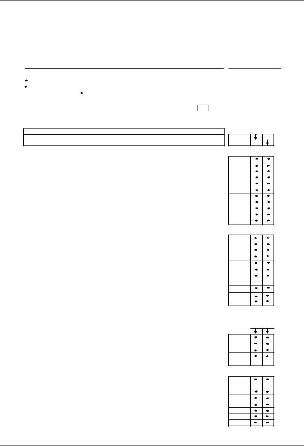
2.3 Model Number Interpretation
Introduction
Write your controller’s model number in the spaces provided below and circle the corresponding items in each table. This information will also be useful when you wire your controller.
Instructions
|
Select the desired key number. The arrow to the right marks the selection available. |
|
||||||||||||
|
Make the desired selections from Tables I through VI using the column below the |
|
||||||||||||
|
proper arrow. |
|
A dot ( |
) denotes availability. |
|
|
|
|
|
|
||||
|
Key Number |
|
I |
|
II |
|
III |
|
IV |
V |
VI |
|||
|
_ _ _ _ _ _ |
- |
_ _ |
- |
_ _ _ _ |
- |
_ _ _ |
- |
_ _ _ _ _ |
- |
_ _ |
|
_ |
|
|
|
|
|
|
|
|
|
|
|
|
|
|
|
|
KEY NUMBER - UDC2500 Single Loop Controller
Description
Digital Controller for use with 90 to 264Vac Power
Digital Controller for use with 24Vac/dc Power
TABLE I - Specify Control Output and/or Alarms
|
None (Can be used as an indicator only) |
|
|
Current Output (4 to 20ma, 0 to 20 ma) |
|
Output #1 |
Electro Mechanical Relay (5 Amp Form C) |
|
Solid State Relay (1 Amp) |
||
|
||
|
Open Collector transistor output |
|
|
Dual 2 Amp Relays (Both are Form A) (Heat/Cool Applications) |
|
|
No Additional Outputs or Alarms |
|
Output #2 and Alarm |
One Alarm Relay Only |
|
#1 or Alarms 1 and 2 |
E-M Relay (5 Amp Form C) Plus Alarm 1 (5 Amp Form C Relay) |
|
|
Solid State Relay (1 Amp) Plus Alarm 1 (5 Amp Form C Relay) |
|
|
Open Collector Plus Alarm 1 (5 Amp Form C Relay) |
TABLE II - Communications and Software Selections
|
None |
|
Communications |
Auxiliary Output/Digital Inputs (1 Aux and 1 DI or 2 DI) |
|
RS-485 Modbus Plus Auxiliary Output/Digital Inputs |
||
|
||
|
10 Base-T Ethernet (Modbus RTU) Plus Auxiliary Output/Digital Inputs |
|
|
Standard Functions, Single Display |
|
Software Selections |
Dual Display with Auto/Manual |
|
Set Point Programming (12 Segments) Dual Display, Auto/Manual |
||
|
||
|
Limit Controller |
|
Reserved |
No Selection |
|
Infrared interface |
None |
|
Infrared Interface Included (Can be used with a Pocket PC) |
||
|
TABLE III - Input 1 can be changed in the field using external resistors
Input 1 |
TC, RTD, mV, 0-5V, 1-5V |
|
TC, RTD, mV, 0-5V, 1-5V, 0-20mA, 4-20mA |
||
|
TC, RTD, mV, 0-5V, 1-5V, 0-20mA, 4-20mA, 0-10V |
|
Input 2 |
None |
|
0-5V, 1-5V, 0-20mA, 4-20mA |
||
|
TABLE IV - Options
Approvals |
CE, UL and CSA (Standard) |
|
CE, UL, CSA and FM |
||
|
||
|
CE Only |
|
Tags |
None |
|
Stainless Steel Customer ID Tag - 3 lines w/22 characters/line |
||
|
||
Future Options |
None |
|
None |
||
|
None |
Selection Availability
DC2500
DC2501
0 _ C _ E _ A _ T _ R _
_ 0 _ B _ E _ A _ T
0 _ _ _ |
|
|
1 _ _ _ |
|
|
2 _ _ _ |
|
|
3 _ _ _ |
|
|
_ 0 _ _ |
|
|
_ A _ _ |
|
|
_ B _ _ |
|
|
_ L _ _ |
a |
a |
_ _ 0 _ |
|
|
_ _ _ 0 |
|
|
_ _ _ R |
|
|
|
Availability |
|
DC 2500 |
2501 |
|
Selection |
|
|
1 _ _ |
|
|
2 _ _ |
|
|
3 _ _ |
|
|
_ 00 |
|
|
_ 10 |
b |
b |
0 _ _ _ _ |
|
|
1 _ _ _ _ |
c |
c |
2 _ _ _ _ |
|
|
_ 0 _ _ _ |
|
|
_ T _ _ _ |
|
|
_ _ 0 _ _ |
|
|
_ _ _ 0 _ |
|
|
_ _ _ _ 0 |
|
|
12 |
UDC2500 Universal Digital Controller Product Manual |
4/07 |

Installation
TABLE V - Product Manuals
|
Product Information on CD - English |
|
|
|
English (Hard Copy) Manual |
(51-52-25-127) |
|
Manuals |
French (Hard Copy) Manual |
(51-52-25-127-FR) |
|
German (Hard Copy) Manual |
(51-52-25-127-DE) |
||
|
|||
|
Italian (Hard Copy) Manual |
(51-52-25-127-IT) |
|
|
Spanish (Hard Copy) Manual |
(51-52-25-127-SP) |
|
Certificate |
None |
|
|
Certificate of Conformance (F3391) |
|
||
|
|
TABLE VI
No Selection |
None |
|
|
|
RESTRICTIONS |
|
|
|
|
Restriction Letters |
Available Only With |
|
Not Available With |
|
Table |
Selection |
Table |
Selection |
|
a |
I |
E _ |
|
|
I |
A _ |
|
|
|
|
I |
T _ |
|
|
Limit Controller Restrictions/Comments: |
|
|
||
1. FM approved units with communications are limited to read only. |
||||
2. UL listed for regulatory use only. |
|
|
||
|
|
|
|
|
b |
|
|
II |
_ L _ _ |
c |
II |
_ L _ _ |
I |
C _, R _ |
0 _
E_
F_
G_
I _
S _
_ 0 _ C
0
Figure 2-1 Model Number Interpretation
4/07 |
UDC2500 Universal Digital Controller Product Manual |
13 |

Installation
2.4 Control and Alarm Relay Contact Information
Control Relays
ATTENTION
Control relays operate in the standard control mode (that is, energized when output state is on).
Table 2-2 Control Relay Contact Information
Unit Power |
Control Relay |
Control Relay |
Output #1 or #2 |
|
Wiring |
Contact |
Indicator Status |
Off |
N.O. |
Open |
Off |
|
|
|
|
|
N.C. |
Closed |
|
|
|
||
|
|
|
|
On |
N.O. |
Open |
Off |
|
|
|
|
|
|
Closed |
On |
|
|
|
|
|
N.C. |
Closed |
Off |
|
|
|
|
|
|
Open |
On |
|
|
|
|
Alarm Relays
ATTENTION
Alarm relays are designed to operate in a failsafe mode (that is, de-energized during alarm sate). This results in alarm actuation when power is OFF or when initially applied, until the unit completes self diagnostics. If power is lost to the unit, the alarms will de-energize and thus the alarm contacts will close.
Table 2-3 Alarm Relay Contact Information
|
Unit |
|
|
Alarm Relay |
|
Variable NOT in Alarm State |
Variable in Alarm State |
||||||
|
Power |
|
|
Wiring |
|
|
|
|
|
|
|
|
|
|
|
|
|
Relay |
|
Indicators |
|
Relay |
|
Indicators |
|
||
|
|
|
|
|
|
|
|
|
|
||||
|
|
|
|
|
|
Contact |
|
|
|
Contact |
|
|
|
|
Off |
|
N.O. |
Open |
|
Off |
Open |
|
Off |
||||
|
|
|
|
N.C. |
Closed |
|
|
|
Closed |
|
|
|
|
|
|
|
|
|
|
|
|
|
|
||||
|
On |
|
N.O. |
Closed |
|
Off |
Open |
|
On |
||||
|
|
|
|
|
|
|
|
|
|
|
|
|
|
|
|
|
|
N.C. |
Open |
|
|
|
Closed |
|
|
|
|
|
|
|
|
|
|
|
|
|
|
|
|
|
|
14 |
UDC2500 Universal Digital Controller Product Manual |
4/07 |
Installation
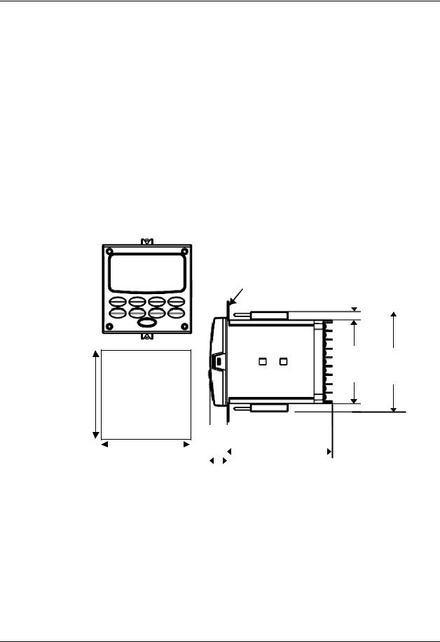
2.5 Mounting
Physical Considerations
The controller can be mounted on either a vertical or tilted panel using the mounting kit supplied. Adequate access space must be available at the back of the panel for installation and servicing activities.
•Overall dimensions and panel cutout requirements for mounting the controller are shown in Figure 2-2.
•The controller’s mounting enclosure must be grounded according to CSA standard C22.2 No. 0.4 or Factory Mutual Class No. 3820 paragraph 6.1.5.
•The front panel is moisture rated NEMA3 and IP55 rated and can be easily upgraded to NEMA4X and IP66.
Overall Dimensions
|
Max. panel thickness |
||||
mm |
19,1 |
|
|
|
|
9,0 |
|
||||
.75 |
|
||||
inches |
0,35 |
|
|||
|
|
||||
|
|
|
|
|
|
|
|
|
|
|
|
|
|
|
|
|
|
92,0 + 0,8 - 0,00
3,62 + 0,03 -0,00
90,6 108,6 3,57 4,28
Panel
Cutout
|
|
|
|
|
|
|
|
|
92,0 |
+ 0,8 |
|
|
|
|
|
|
|
|
|
|
|
|
113,1 |
|||
|
- 0,00 |
|
|
|
|
|
||
|
17,9 |
4,45 |
||||||
3,62 |
+ 0,03 |
|||||||
|
||||||||
0,70 |
|
|||||||
|
-0,00 |
|
||||||
|
|
|
|
|
|
|
||
Figure 2-2 Mounting Dimensions (not to scale)
4/07 |
UDC2500 Universal Digital Controller Product Manual |
15 |
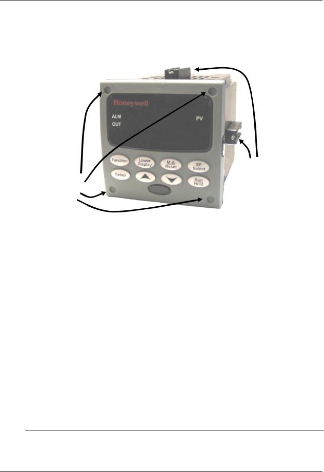
Installation
Mounting Method
Before mounting the controller, refer to the nameplate on the outside of the case and make a note of the model number. It will help later when selecting the proper wiring configuration.
Mounting clips
Attach screws and washers here for water protection
|
|
|
Figure 2-3 Mounting Methods |
Mounting Procedure |
|
||
|
|
|
Table 2-4 Mounting Procedure |
|
Step |
|
Action |
1Mark and cut out the controller hole in the panel according to the dimension information in Figure 2-2.
2Orient the case properly and slide it through the panel hole from the front.
3Remove the mounting kit from the shipping container and install the kit as follows:
•For normal installation two mounting clips are required. Insert the prongs of the clips into the two holes in the top and bottom center of the case (Figure 2-3).
•For water-protected installation four mounting clips are required. There are two options of where to install the mounting clips: 1) Insert the prongs of the clips into the two holes on the left and right side of the top and bottom of the case or 2) on the center on each of the four sides (Figure 2-3).
•Tighten screws to 2 lb-inch (22 N•cm) to secure the case against the panel. CAUTION: Over tightening will cause distortion and the unit may not seal properly.
4For water-protected installation, install four screws with washers into the four recessed areas in the corners of the front bezel (Figure 2-3). Push the point of the screw through the center piercing the elastomeric material and then tighten screws to 5 lb-in (56 N•cm).
16 |
UDC2500 Universal Digital Controller Product Manual |
4/07 |
Loading...