


UDA2182

UDA2182
Universal Dual Analyzer
Product Manual
70-82-25-119
January 2009
Honeywell Process Solutions

WARRANTY/REMEDY
Honeywell warrants goods of its manufacture as being free of defective materials and faulty
workmanship. Contact your local sales office for warranty information. If warranted goods are
returned to Honeywell during the period of coverage, Honeywell will repair or replace without charge
those items it finds defective. The foregoing is Buyer's sole remedy and is in lieu of all other
warranties, expressed or implied, including those of merchantability and fitness for a particular
purpose. Specifications may change without notice. The information we supply is believed to be
accurate and reliable as of this printing. However, we assume no responsibility for its use.
While we provide application assistance personally, through our literature and the Honeywell web
site, it is up to the customer to determine the suitability of the product in the application.
Notices and Trademarks
Copyright 2008 by Honeywell
Revision 5 January 2009
Honeywell Process Solutions
Honeywell
2500 W. Union Hill Drive
Phoenix, Arizona 85027
UDA2182 is a U.S. registered trademark of Honeywell
Other brand or product names are trademarks of their respective owners.
ii UDA2182 Universal Dual Analyzer Product Manual January 2009

About This Document
Abstract
This document provides descriptions and procedures for the Installation, Configuration, Operation, and Troubleshooting of
your UDA2182 Universal Dual Analyzer.
Contacts
World Wide Web
The following lists Honeywell’s World Wide Web sites that will be of interest to our customers.
Honeywell Organization WWW Address (URL)
Corporate http://www.honeywell.com
Honeywell Field Solutions http://www.honeywell.com/ps
Technical tips http://content.honeywell.com/ipc/faq
Telephone
Contact us by telephone at the numbers listed below.
United States and Canada Honeywell 1-800-423-9883 Tech. Support
Organization Phone Number
1-800-525-7439 Service
January 2009 UDA2182 Universal Dual Analyzer Product Manual iii
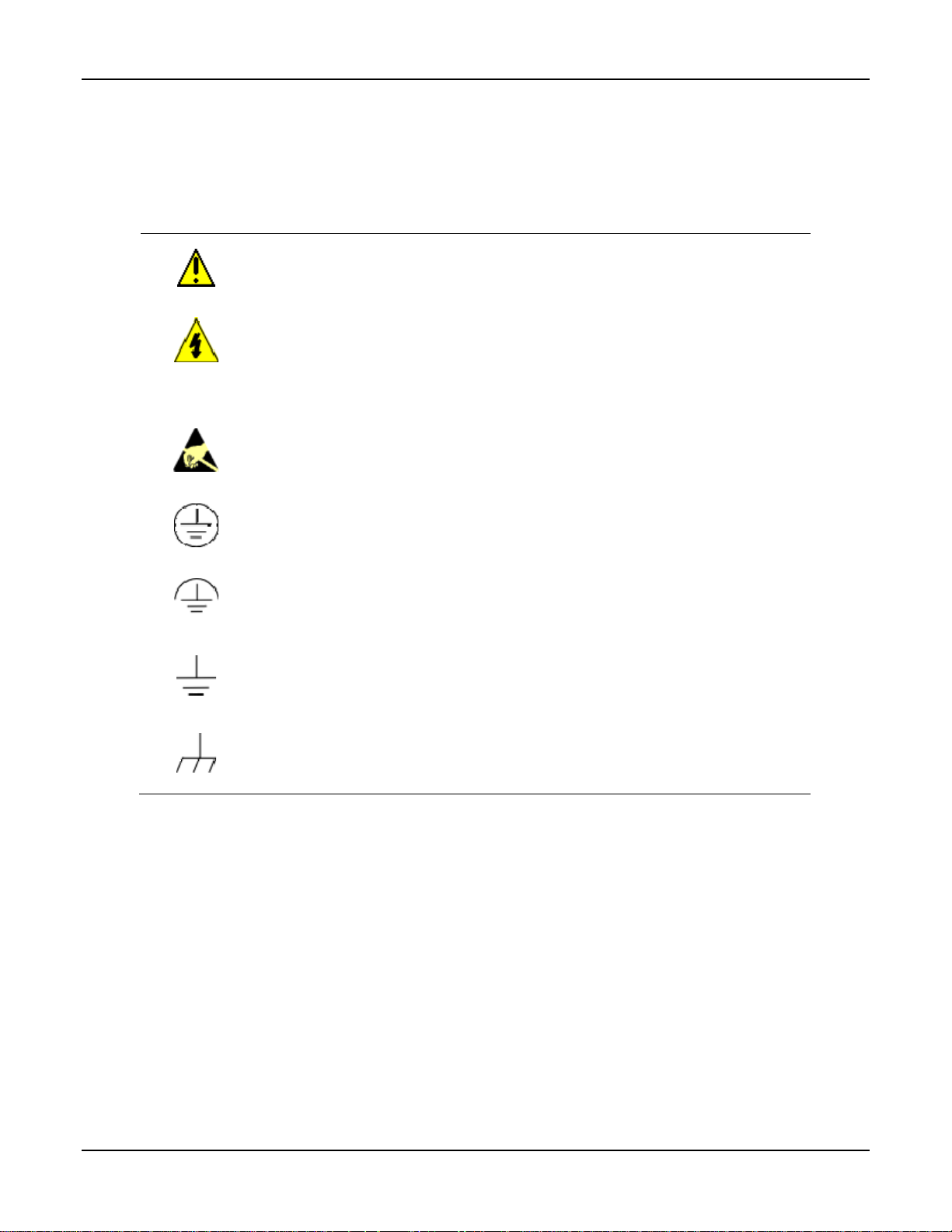
Symbol Definitions
The following table lists those symbols used in this document to denote certain conditions.
Symbol Definition
This CAUTION symbol on the equipment refers you to the Product Manual for
additional information. This symbol appears next to required information in the manual.
WARNING
PERSONAL INJURY: Risk of electrical shock. This symbol warns you of a potential
shock hazard where HAZARDOUS LIVE voltages greater than 30 Vrms, 42.4 Vpeak,
or 60 VDC may be accessible. Failure to comply with these instructions could result in
death or serious injury.
ATTENTION, Electrostatic Discharge (ESD) hazards. Observe precautions for
handling electrostatic sensitive devices
Protective Earth (PE) terminal. Provided for connection of the protective earth (green
or green/yellow) supply system conductor.
Functional earth terminal. Used for non-safety purposes such as noise immunity
improvement. NOTE: This connection shall be bonded to protective earth at the source
of supply in accordance with national local electrical code requirements.
Earth Ground. Functional earth connection. NOTE: This connection shall be bonded to
Protective earth at the source of supply in accordance with national and local electrical
code requirements.
Chassis Ground. Identifies a connection to the chassis or frame of the equipment shall
be bonded to Protective Earth at the source of supply in accordance with national and
local electrical code requirements.
iv UDA2182 Universal Dual Analyzer Product Manual January 2009

Contents
1 INTRODUCTION ...................................................................................................1
1.1 Overview.........................................................................................................................................1
1.2 Features...........................................................................................................................................3
2 SPECIFICATIONS.................................................................................................5
2.1 Specifications..................................................................................................................................5
2.2 CE Conformity (Europe).................................................................................................................7
3 UNPACKING, PREPARATION, AND MOUNTING...............................................9
3.1 Overview.........................................................................................................................................9
3.2 Unpacking and Preparing..............................................................................................................10
3.3 Mounting.......................................................................................................................................10
4 POWER WIRING.................................................................................................15
4.1 Overview.......................................................................................................................................15
4.2 General Wiring Practices..............................................................................................................16
4.3 Power Wiring Considerations.......................................................................................................17
4.4 Installing Power Wiring................................................................................................................17
5 OPERATING THE ANALYZER...........................................................................20
5.1 Overview.......................................................................................................................................20
5.2 Analyzer Overview.......................................................................................................................21
5.3 Key Navigation.............................................................................................................................22
5.4 Displays Overview........................................................................................................................23
5.5 Input Displays...............................................................................................................................25
5.6 PID Displays.................................................................................................................................26
5.7 Auto Cycle Displays .....................................................................................................................28
5.7.1 Overview............................................................................................................................ 28
5.7.2 Access to Auto Cycle Displays..........................................................................................28
5.7.3 How it works......................................................................................................................29
5.7.4 Displays..............................................................................................................................29
5.7.5 Hold Active........................................................................................................................30
5.7.6 Probe Transit......................................................................................................................30
5.7.7 Cycle Start Src ...................................................................................................................30
5.7.8 Cycle Interval.....................................................................................................................30
5.7.9 Rinse Cycle Cnt .................................................................................................................30
5.7.10 Rinse Mins......................................................................................................................30
5.7.11 Resume Dly Mins...........................................................................................................30
3/08 UDA2182 Universal Dual Analyzer Product Manual v

5.7.12 Manual Starting/Stopping the Auto Cycle .....................................................................31
5.7.13 Auto Cycle Fail ..............................................................................................................32
5.7.14 Conditional Sequencer Steps..........................................................................................32
5.8 Pharma Display............................................................................................................................. 33
5.8.1 Overview............................................................................................................................ 33
5.8.2 How it works......................................................................................................................33
5.8.3 Access to Pharma Display..................................................................................................34
5.8.4 Displays..............................................................................................................................34
5.8.5 Pharma Warning and Fail Signal .......................................................................................36
5.9 Cation Calc Display......................................................................................................................37
5.9.1 Overview............................................................................................................................ 37
5.9.2 How it works......................................................................................................................37
5.9.3 pH Calculation from Specific and Cation Conductivity Setup..........................................38
5.9.4 Calibration..........................................................................................................................39
5.9.5 CO2 by Degassed Conductivity..........................................................................................39
5.9.6 Access to Cation Display...................................................................................................39
5.9.7 Troubleshooting.................................................................................................................40
5.10 Status Display............................................................................................................................41
5.11 Event History.............................................................................................................................46
5.12 Process Instrument Explorer Software......................................................................................48
5.13 Modbus Communications..........................................................................................................50
6 CONFIGURATION...............................................................................................51
6.1 Overview.......................................................................................................................................51
6.2 UDA2182 Block Diagram ............................................................................................................52
6.3 Main Setup Menu..........................................................................................................................53
6.4 Basic Configuration Procedure.....................................................................................................55
6.4.1 General Rules for Editing...................................................................................................55
6.5 Analog and Digital Signal Sources...............................................................................................58
6.6 Inputs Configuration.....................................................................................................................63
6.7 Outputs Configuration ..................................................................................................................74
6.8 Relays Configuration....................................................................................................................76
6.9 Alarms Configuration ...................................................................................................................81
6.10 Monitors Configuration.............................................................................................................83
6.11 Math Configuration...................................................................................................................85
6.12 Logic Configuration..................................................................................................................87
6.13 Auxiliary Configuration............................................................................................................89
6.14 PID Control Configuration........................................................................................................92
6.15 Auto Cycling Configuration....................................................................................................100
6.15.1 Overview ......................................................................................................................100
6.15.2 Accessing Auto Cycle Menu........................................................................................100
6.15.3 Auto Cycling Configuration.........................................................................................101
6.15.4 pH Auto Cycling Configuration Example....................................................................103
vi UDA2182 Universal Dual Analyzer Product Manual January 2009

6.16 Variables Configuration..........................................................................................................105
6.17 Communication Configuration................................................................................................106
6.18 Maintenance Configuration.....................................................................................................108
7 INPUTS AND OUTPUTS WIRING.....................................................................114
7.1 Overview.....................................................................................................................................114
7.2 General Wiring Practices............................................................................................................115
7.3 Inputs and Outputs......................................................................................................................117
7.4 Direct pH/ORP Input Wiring Diagrams......................................................................................120
7.5 pH Input from External Preamplifier/Cap Adapter Wiring Diagrams........................................126
7.6 Conductivity................................................................................................................................130
7.7 Dissolved Oxygen.......................................................................................................................131
7.8 Communications Card.................................................................................................................133
7.9 Outputs........................................................................................................................................134
7.10 Option Card.............................................................................................................................135
8 INPUT CALIBRATION.......................................................................................136
8.1 Overview.....................................................................................................................................136
8.2 Calibration Menu........................................................................................................................137
8.3 pH/ORP and Conductivity Overview .........................................................................................138
8.4 Recommendations for Successful Measurement and Calibration...............................................139
8.5 pH Calibration.............................................................................................................................140
8.5.1 Introduction......................................................................................................................140
8.5.2 Calibrating pH Electrodes Using Automatic Buffer recognition.....................................141
8.5.3 Buffering Method of Calibrating pH Electrodes..............................................................145
8.5.4 Sample Method of Calibrating pH Electrodes ................................................................. 148
8.5.5 Viewing and resetting pH Offset and (Standardization) pH Slope..................................150
8.6 ORP Calibration..........................................................................................................................151
8.6.1 Introduction......................................................................................................................151
8.6.2 ORP Calibration Using Reference Solution.....................................................................151
8.6.3 ORP Calibration Using Voltage Input .............................................................................154
8.6.4 Viewing and Resetting ORP Offset .................................................................................156
8.7 Conductivity Calibration.............................................................................................................157
8.7.1 Introduction......................................................................................................................157
8.7.2 Entering the Cal Factor for each cell................................................................................157
8.7.3 Determining and Entering the TDS Conversion Factor...................................................157
8.7.4 Determining TDS conversion factor................................................................................158
8.7.5 Performing Calibration Trim............................................................................................159
8.7.6 Resetting Calibration Trim...............................................................................................162
8.7.7 Cation pH Calibration......................................................................................................163
8.7.8 Resetting pH Offset..........................................................................................................165
8.8 Dissolved Oxygen Calibration....................................................................................................166
3/08 UDA2182 Universal Dual Analyzer Product Manual vii

9 OUTPUTS CALIBRATION................................................................................178
9.1 Overview.....................................................................................................................................178
9.2 Output Calibration ......................................................................................................................179
10 TEMPERATURE INPUT CALIBRATION ..........................................................185
10.1 Overview.................................................................................................................................185
10.2 Temperature Input Calibration................................................................................................186
11 CALIBRATION HISTORY .................................................................................189
11.1 Overview.................................................................................................................................189
11.2 Clear Calibration History ........................................................................................................190
12 DIAGNOSTICS AND MESSAGES....................................................................191
12.1 Overview.................................................................................................................................191
12.2 System Status Messages..........................................................................................................192
12.3 Calibration Diagnostics...........................................................................................................193
12.4 Auto Cycle Fail Messages.......................................................................................................194
12.5 Pharma Fail Messages.............................................................................................................195
13 ETHERNET AND COMMUNICATIONS ............................................................196
13.1 Overview.................................................................................................................................196
14 ACCESSORIES AND REPLACEMENT PARTS LIST......................................197
14.1 Overview.................................................................................................................................197
14.2 Part Numbers...........................................................................................................................198
15 APPENDICES....................................................................................................199
15.1 Table of Contents ....................................................................................................................199
15.2 Appendix A – Entering Values for Lead Resistance Compensation.......................................200
15.3 Appendix B – Entering Values for Lead Resistance Compensation [Titanium Cells]............202
15.4 Appendix C - Cyanide Waste Treatment.................................................................................204
15.5 Appendix D – Chrome Waste Treatment................................................................................208
15.6 Appendix E – Two-cell Applications......................................................................................212
15.7 Appendix F – Using a Precision Check Resistor (For Conductivity) ....................................216
15.8 Appendix G – Noise Testing, Dissolved Oxygen Application................................................218
15.9 Appendix H – DO Probe and Analyzer Tests .........................................................................219
15.10 Appendix I – Parameters Affecting Dissolved Oxygen Measurement................................222
15.11 Appendix J – Discussion on Chemical Interferences on Measured DO Currents ...............223
15.12 Appendix K – Percent Saturation Readout..........................................................................225
viii UDA2182 Universal Dual Analyzer Product Manual January 2009

15.13 Appendix L – Leak Detection in PPB Applications............................................................226
15.14 Appendix M – Procedure for Low Level ppb Dissolved Oxygen Testing ..........................227
15.15 Appendix N – Sample Tap Electrode Mounting Recommendations...................................229
15.16 Appendix O – Auto Clean and Auto Cal Examples ............................................................231
15.17 Appendix P – AutoClean and AutoCal Theory and Piping.................................................234
15.17.1 AutoCal Sequence and Piping......................................................................................235
INDEX..........................................................................................................................239
3/08 UDA2182 Universal Dual Analyzer Product Manual ix

Tables
Table 3-1 Procedure for Unpacking and Preparing the UDA2182 ______________________________ 10
Table 3-2 Panel Mounting Procedure ____________________________________________________ 11
Table 4-1 Procedure for installing AC Power Wiring________________________________________ 17
Table 5-1 Function of Keys____________________________________________________________ 22
Table 5-2 Display Details Functions_____________________________________________________ 24
Table 5-3 Changing PID Parameters on the Display_________________________________________ 27
Table 5-4 Manually Starting/Stopping the Auto Cycle_______________________________________ 31
Table 5-5 Conditional Sequencer Steps for Auto Cycle ______________________________________ 32
Table 5-6 Selecting the Pharma Test on Display ___________________________________________ 35
Table 5-7 Status Display Details________________________________________________________ 41
Table 6-1 Basic Configuration Procedure_________________________________________________ 56
Table 6-2 Signal Sources______________________________________________________________ 58
Table 6-3 Analog Signal Sources _______________________________________________________ 59
Table 6-4 Digital Signal Sources________________________________________________________ 60
Table 6-5 Input Configuration__________________________________________________________ 63
Table 6-6 Outputs Configuration________________________________________________________ 74
Table 6-7 Relays Configuration ________________________________________________________ 77
Table 6-8 Alarms Configuration ________________________________________________________ 82
Table 6-9 Monitors Configuration_______________________________________________________ 83
Table 6-10 Math Configuration_________________________________________________________ 86
Table 6-11 Logic Configuration ________________________________________________________ 88
Table 6-12 Auxiliary Configuration _____________________________________________________ 90
Table 6-13 PID Configuration __________________________________________________________ 94
Table 6-14 PID Tuning _______________________________________________________________ 97
Table 6-15 PID Alarms _______________________________________________________________ 98
Table 6-16 Auto Cycling Configuration _________________________________________________ 101
Table 6-17 Example Auto Cycling Configuration for pH____________________________________ 103
Table 6-18 Variables Configuration ____________________________________________________ 105
Table 6-19 Communication Configuration _______________________________________________ 106
Table 6-20 Maintenance Configuration__________________________________________________ 108
Table 7-1 Recommended Maximum Wire Size ___________________________________________ 116
Table 7-2 Procedure for installing Input and Output wiring__________________________________ 119
Table 8-1 Standard pH Buffer Values___________________________________________________ 142
Table 8-2 Calibrating pH Electrodes Using Automatic Buffer Recognition______________________ 143
Table 8-3 Procedure for Buffering Method of Calibrating pH Electrodes _______________________ 146
Table 8-4 Procedure for Sample Method of Calibrating pH Electrodes _________________________ 148
Table 8-5 Oxidation-Reduction Potential of Reference Solutions at Specified Temperature________ 152
Table 8-6 Procedure for Calibrating ORP System Using a Reference Solution ___________________ 152
Table 8-7 Procedure for Calibrating ORP Analyzer Using Voltage Input _______________________ 154
Table 8-8 Conductivity of Potassium Chloride Solutions at 25 °C_____________________________ 160
Table 8-9 Procedure for Performing Calibration Trim Using a Reference Solution________________ 160
Table 8-10 Procedure for Sample Method of Calibrating Cation pH ___________________________ 163
Table 8-11 Calibrating a Dissolved Oxygen Probe Using Air Calibration Method ________________ 167
Table 8-12 Calibrating a Dissolved Oxygen Probe Using Sample Calibration Method_____________ 169
Table 8-13 Calibrating the Integral Pressure Sensor________________________________________ 171
Table 8-14 Running a Probe Bias Scan__________________________________________________ 174
Table 9-1 Procedure for Calibrating Analyzer Outputs______________________________________ 181
Table 10-1 Procedure for Calibrating the Temperature Inputs ________________________________ 186
x UDA2182 Universal Dual Analyzer Product Manual January 2009

Table 11-1 Cal History items _________________________________________________________ 189
Table 12-1 Status Messages __________________________________________________________ 192
Table 12-2 Probe Calibration Diagnostics________________________________________________ 193
Table 12-3 Auto Cycle Fail Messages___________________________________________________ 194
Table 12-4 Pharma Fail Messages______________________________________________________ 195
Table 14-1 Part Numbers_____________________________________________________________ 198
Table 15-1 Data for Concentration Range Measurements ___________________________________ 217
Table 15-2 Dissolved Oxygen Solubility vs. Temperature ___________________________________ 225
Figures
Figure 3-1 Panel Mounting Dimensions (not to scale) _______________________________________ 11
Figure 3-2 Rear Panel Support Plate Dimensions___________________________________________ 12
Figure 3-3 Pipe Mounting Dimensions (not to scale) ________________________________________ 13
Figure 3-4 Wall Mounting Dimensions (not to scale)________________________________________ 14
Figure 4-1 Power Wiring______________________________________________________________ 19
Figure 5-1 UDA2182 Operator Interface (all display items shown)_____________________________ 21
Figure 5-2 Example – Two Input Display_________________________________________________ 25
Figure 5-3 PID Loop 1 Edit Display screen example ________________________________________ 26
Figure 5-4 Auto Cycle Display screen example ____________________________________________ 28
Figure 5-5 Pharma Display screen example _______________________________________________ 34
Figure 5-6 UDA for Cation and Degassed CO2_____________________________________________ 37
Figure 5-7 Cation Display screen example for pH calculations ________________________________ 39
Figure 5-8 Status Display screen example ________________________________________________ 41
Figure 5-9 Event History Display screen example __________________________________________ 46
Figure 5-10 Alarm Event Display screen example (Read Only)________________________________ 46
Figure 5-11 Screen capture of Process Instrument Explorer running on a Pocket PC_______________ 48
Figure 6-1 UDA2182 Block Diagram____________________________________________________ 52
Figure 7-1 Wiring Terminals and board Location__________________________________________ 118
Figure 7-2 Terminal Designations for Durafet III Electrode__________________________________ 120
Figure 7-3 Terminal Designations for Durafet II Electrode __________________________________ 121
Figure 7-4 Terminal Designations for Meredian II Electrode_________________________________ 122
Figure 7-5 Terminal Designations for Meredian II Electrode with Quick Disconnect______________ 122
Figure 7-6 Terminal Designations for ORP ______________________________________________ 123
Figure 7-7 Terminal Designations for Direct pH/ORP with Quick Disconnect Option_____________ 123
Figure 7-8 Terminal Designations for HPW7000 System____________________________________ 124
Figure 7-9 Terminal Designations for HB Series pH or ORP_________________________________ 125
Figure 7-10 Terminal Designations for Meredian Electrode with External Preamplifier____________ 126
Figure 7-11 Terminal Designations for Durafet II Electrode with External Preamplifier____________ 127
Figure 7-12 Terminal Designations for Durafet II Electrode with Cap Adapter___________________ 128
Figure 7-13 Terminal Designations for Durafet III Electrode with Cap Adapter __________________ 129
Figure 7-14 Terminal Designations for Conductivity with Integral Cable _______________________ 130
Figure 7-15 Terminal Designations for Conductivity Cells with Quick Disconnect _______________ 130
Figure 7-16 Terminal Designations for Dissolved Oxygen with Integral Cable___________________ 131
Figure 7-17 Terminal Designations for Dissolved Oxygen with Quick Disconnect Option _________ 132
Figure 7-18 Terminal Designations for Communications Card _______________________________ 133
Figure 7-19 Terminal Designations for Power, Analog Output, and Relay Output ________________ 134
Figure 7-20 Terminal Designations for Option Board ______________________________________ 135
Figure 8-1 Resetting pH Offset and pH Slope_____________________________________________ 150
3/08 UDA2182 Universal Dual Analyzer Product Manual xi

Figure 8-2 Resetting ORP Offset ______________________________________________________ 156
Figure 8-3 Resetting Calibration Trim __________________________________________________ 162
Figure 8-4 Resetting pH Offset ________________________________________________________ 165
Figure 8-5 Display of Probe Bias Test Done in Air ________________________________________ 173
Figure 8-6 Resetting Pressure Offset or Bias Volts_________________________________________ 177
Figure 9-1 Resetting Output 1 Offsets (example) __________________________________________ 184
Figure 10-1 Resetting temperature offset ________________________________________________ 188
Figure 15-1 Example of a Conductivity Loop_____________________________________________ 200
Figure 15-2 Example of a Conductivity Loop_____________________________________________ 202
Figure 15-3 Cyanide Treatment System _________________________________________________ 204
Figure 15-4 First Stage Cyanide Oxidation - Typical Titration Curve __________________________ 205
Figure 15-5 Chrome Treatment System _________________________________________________ 208
Figure 15-6 Chrome Reduction - Typical Titration Curve ___________________________________ 209
Figure 15-7 Suggested ppb Dissolved Oxygen Test Set-up __________________________________ 228
Figure 15-8 Typical Probe Installation __________________________________________________ 229
Figure 15-9 Auto Clean Setup_________________________________________________________ 232
Figure 15-10 Auto Cal Setup__________________________________________________________ 233
Figure 15-11 Automatic Electrode Wash Setup __________________________________________ 235
Figure 15-12 Rinse and One-Point Calibration____________________________________________ 236
Figure 15-13 Two-Point AutoCal Operation______________________________________________ 237
xii UDA2182 Universal Dual Analyzer Product Manual January 2009

Introduction
1 Introduction
1.1 Overview
Multi-function instrument
The UDA2182 Universal Dual Analyzer is the next level of dual channel analyzers
providing unprecedented versatility and flexibility.
The UDA2182 can accept single or dual inputs from Honeywell Direct pH, pH from
preamp, ORP (Oxidation Reduction Potential), Contacting Conductivity and Dissolved
Oxygen sensors. Measurements for Dual channel units can be arranged in any
combination of measurement.
User interface
“Process Information at a Glance” is a unique feature of the UDA2182 graphical
backlit LCD.
Two PV values with corresponding UOM (unit of measure), temperature, alarm state,
scales, and limits, tagging, and status messages can be displayed simultaneously.
Ten dedicated keys provide direct access to Setup configuration menus and sub-menus
and Calibration.
Easy to configure
Menu-driven configuration of the UDA2182 is intuitive, fast and easy. A Setup menu is
provided for every configuration task. You will be permitted to configure only those
parameters relevant to your application and supported by the Analyzer model you
purchased.
In fact, Setup configuration screens will contain only prompts and menu choices that
apply to your application.
Multi-language prompts guide the operator step-by-step through the configuration
process assuring quick and accurate entry of all configurable parameters. Nine languages
are available via configuration: English, French, German, Spanish, Italian, Russian,
Turkish, Polish and Czech.
Inputs
Analytical measurements of Direct pH, pH from preamp, ORP, Conductivity and
Dissolved Oxygen (ppm or ppb) can all be done in one analyzer. The unit can be used as
a single input or dual input instrument – you decide what measurements are included.
The input boards are factory calibrated and easily replaced. Addition of additional relays
or an analog output is done with a single board. The “Mix –n- Match” design reduces
inventory and increases flexibility. You can purchase a basic unit and then add input and
output boards as needed.
January 2009 UDA2182 Universal Dual Analyzer Product Manual 1

Introduction
Outputs
Two standard Analog outputs 0 –20 or 4–20 mAdc, 750 ohms maximum, isolated from
inputs, ground, and each other, and independently assignable to any parameters and
ranges Proportional to user-set output range(s) of selected parameter(s).
One optional Analog output 0 –20 or 4–20 mAdc, 750 ohms maximum, isolated from
inputs, ground, and each other, and independently assignable to any parameters and
ranges.
Relays
Two 4A SPDT alarm/control relays are standard; with an additional two 4A relays
available as an option.
Infrared Communications
The infrared connection provides a non-intrusive wireless connection with the instrument
and maintains its weather tight integrity when combined with the optional PIE (Process
Instrument Explorer).
No need to get access to the back of the analyzer to communicate with the instrument, no
need to take your screw driver to wire the communication cable, no wiring mistake
possible. You can now duplicate an instrument’s configuration, upload or download a
new configuration in a matter of seconds, just by pointing your Pocket PC in the direction
of the instrument.
Communications Card (Optional)
The Communication card provides one Serial Port and one Ethernet Port.
Serial port provides
RS422/RS485 multi-drop
Modbus RTU protocol to read signals and read/write variables
Ethernet port provides:
Multi-language web pages to monitor readings, alarms, statuses, events
Multi-language web pages to setup Ethernet port settings
Multi-language email to send alarm status changes
Modbus TCP protocol to read signals and read/write variables
Both ports can communicate to a PIE tool
2 UDA2182 Universal Dual Analyzer Product Manual January 2009

Introduction
1.2 Features
Standard and solution temperature compensation
Measured pH temperature is compensated in one of two ways. Electrode temperature
sensitivity is automatically compensated to display the correct pH value at temperature.
In addition, displayed pH can be optionally normalized to a solution temperature of 25°C
as determined by the current Solution Temperature Coefficient, which is expressed in
units of pH/°C with precision to the hundredths decimal place. The parameter “Solu
Temp Coeff” allows the selection of Pure Water, Ammonia, Phosphate, Morpholine, and
Custom or None (User Entry).
Measured Conductivity and Resistivity can optionally be temperature compensated to
25°C for a specific solution type. TDS and concentration are always measured based on a
specific solution type. The cell constant and measurement type determines which solution
types are available for selection.
Dissolved Oxygen accurately measures the concentration of dissolved oxygen in water.
The Analyzer energizes the probe and receives dissolved oxygen and temperature signals.
Optional salinity compensation is provided. The Analyzer provides for Air or Sample
calibration with ambient temperature and atmospheric pressure compensation.
Calculated pH
High purity water pH can be calculated from Specific and Cation conductivities to be
used as a check on in-line high purity water pH measurements.
Automatic buffer recognition
“Buffer Group” types NIST/USP, USA, or Europe determines the set of standard pH
buffer values to be used for Zero and Slope calibration by automatic buffer recognition.
Each of the available Buffer Groups is a set of 5 or 6 pH buffer standards.
Solution Temperature Compensation
For high purity water measurement you can select pre-set compensations or configure
custom values.
USP26 Alarm Capabilities
Relays can be configured to alarm on conductivity values as determined by the USP26
standards.
Computed Variables
The availability of calculated variables in the list of available sources for alarms, math
and control and for status display is determined by similarity of units of measure between
the two input boards. For example with Dual Conductivity, %Rejection/Passage,
Difference, or Ratio can be displayed and assigned to the outputs or alarms.
CO2 concentration in ppm can be calculated from de-gassed conductivity measurement.
January 2009 UDA2182 Universal Dual Analyzer Product Manual 3

Introduction
Password protection
Keyboard security protects configuration and calibration data. A password (up to four
digits) can be configured. If the security feature is enabled, the password will be required
to access configuration and calibration software functions.
Auto Clean/Auto Cal
Built-in real time clock is used to set-up versatile cycles that can be used to initiate
automatic sensor cleaning and then calibration.
Diagnostic/Failsafe Outputs
Continuous diagnostic routines detect failure modes, trigger a failsafe output value and
identify the failure to minimize troubleshooting time. The UDA2182 Analyzer performs
extensive self-diagnostics as a background task during normal operation. If a problem is
detected, a message is displayed on the Message stripe to alert the operator. In addition,
the operator can initiate keypad and display tests using Maintenance Menu functions.
High Noise Immunity
The analyzer is designed to provide reliable, error-free performance in industrial
environments that often affect highly noise-sensitive digital equipment.
Watertight corrosion-resistant case
CSA Type 4X (NEMA 4X) rated enclosure permits use in applications where it may be
subjected to moisture, dust, or hose-down conditions. The UDA2182 is designed for
panel, pipe or wall mounting.
4 UDA2182 Universal Dual Analyzer Product Manual January 2009

Specifications
2 Specifications
2.1 Specifications
UDA2182 Universal Dual Analyzer
Display Graphical LCD with white LED Backlight
Viewing Area: 66.8 mm (W) X 35.5 mm (H)
Dot Pixels: 128 (W) X 64 (H)
Display Ranges pH:
Keypad 10 Button Membrane Switch w/Directional Functionality
Case Material GE Valox® 357 (un-reinforced thermoplastic polyester)
Performances (Under
reference operating
conditions)
Operating Conditions Ambient Temperature
Standard Analog Output Two 0-20 mAdc or 4-20 mAdc, 750 ohms max., isolated from inputs, ground, and each other,
Optional Analog Output One 0-20 mAdc or 4-20 mAdc, 750 ohms max., isolated from inputs, ground, and each other.
0-14 pH
Temperature: -10 to 110°C (14 to 230°F)
ORP:
-1600 to +1600 mV
Conductivity:
0.01 Cell: 0-2 uS/cm displayable to 200 uS/cm; 0-0.2 mS/cm;
0-2,000 ppb TDS; 0-200 ppm TDS
0.1 Cell: 0-20 uS/cm displayable to 2000 uS/cm; 0-2 mS/cm,
0-2,000 ppb TDS; 0-2,000 ppm TDS,
1.0 Cell: 0-200 uS/cm displayable to 20,000 uS/cm; 0-20 mS/cm;
0-200 ppm TDS; 0-20 ppt TDS
10 Cell: 0-2,000 uS/cm displayable to 99999 uS/cm; 0-200 mS/cm;
0-2,000 ppm TDS; 0-200 ppt TDS
25 Cell: 0-20,000 uS/cm displayable to 99999 uS/cm; 0-500 mS/cm;
0-10% Concentration displayable to 20%
50 Cell: 0-20,000 uS/cm displayable to 99999 uS/cm; 0-1,000 mS/cm;
0-20% Concentration
Temperature: 0 to + 140°C (32 to 284°F)
Dissolved Oxygen:
0 - 20 ppm
0 –200 ppb, displayable to 20000 ppb
0 – 100% saturation, displayable to 200% saturation
Temperature: 2 – 60°C (35.6 – 104°F), must not freeze
UV/Solvent/Abrasion Resistant
Accuracy: 0.5% of reading
Output Accuracy: +/- 0.01 mA
Drift: Negligible
Repeatability: 0.05%
Temperature Accuracy:
pH and Conductivity Thermistor: +/- 0.1°C from –10 to 100° C, +/- 1.0° C from 101° to 140° C
pH 1000 ohm RTD: +/- 0.4° C
D.O. Thermistor: +/- 0.1° C from 0 to 60° C
Reference Operating Conditions: 25 +/- 1° C; 10-40% RH; 120 or 240 Vac
Operating: 0 to 60°C (32 to 140°F)
Storage: -30 to 70°C (-22 to 158°F)
RH: 5 to 90% max. Non-condensing up to 40°C (104°F). For higher temperatures the RH specification
is derated to maintain constant moisture content
Vibration:
5-15 Hz disp 8 mm pk to pk
15-200 Hz accel 2 G
Independently field-assignable to any parameters and ranges.
Proportional to user-set output range(s) of selected parameter(s),
Independently field-assignable to any parameters and ranges
January 2009 UDA2182 Universal Dual Analyzer Product Manual 5

Specifications
UDA2182 Universal Dual Analyzer
Control Loop/Outputs Control Loops: 2 standard (one for each PV); current, pulse frequency, or time proportional
Control Loop Types: PID (optional), Duplex (optional), On/Off (standard)
Auto-tuning: Accutune II, fuzzy logic overshoot suppression, applicable to both PID loops
Standard Alarm/ Control
Relays
Optional Additional
Alarm/Control Relays
Alarm/Control Settings Alarm/on-off control delay: 0-100 seconds.
Remote Preamplifier Input
Option
pH Temperature
Compensation
Calculated pH from
Differential Conductivity
Auto Buffer Recognition
(pH)
Conductivity
Compensations
Dissolved Oxygen
Measurement
Auto Clean/ Auto Cal
Function
Event History Screen Event history screen stores 256 events with a description of the event and a Date/time stamp.
Calibration History Screen Calibration history screen stores information on 128 calibration events with a date/time stamp.
Power Requirements 90 -264 Vac, 47-63 Hz, 15 VA. Memory retained by E2PROM when power is off.
Wireless Interface
RS422/RS485 Modbus
RTU Slave
Communications Interface
(Optional)
Two SPDT (Form “C”) Relays
Resistive Load Rating: 4A, 120/240 Vac
Two SPDT (Form “C”) Relays
Resistive Load Rating: 4A, 120/240 Vac
Alarm/on-off control deadbands: individually set, from 1 count to full scale for pH, ORP, and
temperature.
On/off cycle period: 0 to 1000 seconds.
On/off percent “on” time: 0 to 100%, 1% resolution.
Set point and proportional band limit ranges: ±19.99 pH, ±1999 mV, -10 to 130°C, 1 count resolution.
DAT cycle period: 1 to 1999 seconds.
PFT maximum frequency: 1 to 200 pulses/minute.
PFT pulse width: 50 ms, compatible with electronic pulse-type metering pumps.
Optional input card to accept input signal from Honeywell digital preamplifiers:
Meridian II – 31075707 and 31022283
Durafet – 31079288 and Cap Adapter cables
Conventional compensation for changing electrode output (Nernst response), plus selectable solution
temperature compensation for high-purity water.
User selectable when unit has two Conductivity inputs. Used when ammonia or amine is the water
treatment chemical.
User Selectable
Available Buffer Series: NIST/USP, US, and Euro
NaCl, HCl, H
Max flowrate (probe): 950 ml/min with flow chamber; no dependence on stirring or flowrate
Atmospheric pressure: 500-800 mm Hg with internal sensor, for calibration
Calibration with either Air or Sample
Real time clock is used to set-up cycles to initiate a cleaning and calibration sequence. Cycle Set-up is
user configurable.
Type: Infrared (IR)
Length of Link: 0 –1 M, 0 –15° Offset
Baud Rate: 9600
Data Format: Modbus Protocol
Baud Rate: 2400, 4800, 9600, 19200, 38400, 57600, or 115200 selectable
Data Format:: IEEE floating point and 32-bit integer. Word swap configurable.
Length of Link:
2000 ft (600 m) max. with Belden 9271 Twinax Cable and 120 ohm termination resistors
4000 ft (1200 m) max. with Belden 8227 Twinax Cable and 100 ohm termination resistors
Link Characteristics: Two-wire (half-duplex), multi-drop Modbus RTU protocol, 15 drops maximum or
up to 31 drops for shorter link length.
Modbus RTU slave: Provides monitoring of inputs outputs, statuses, alarms, and variables. Provides
writing of variables for remotely modifying parameter settings.
, PO4, NaOH, NH3, C4H9C, Pure Water, Custom (User Selectable)
2SO4
6 UDA2182 Universal Dual Analyzer Product Manual January 2009

Specifications
UDA2182 Universal Dual Analyzer
Ethernet TCP/IP
Communications Interface
(Optional)
Safety Compliance UL/CSA General Purpose
CE Compliance CE Conformity (Europe): CE Mark on all models signifies compliance to EMC Directive 84/336/EEC
Case Dimensions 156 mm X 156 mm X 150 mm (6.14” X 6.14” X 5.91”)
Enclosure Rating CSA Type 4X (NEMA 4X) rated enclosure
Installation Ratings Installation Category (Overvoltage Category): Category II
Weight Approx 3 lbs (6.6kg)
Mounting Panel mounting-hardware supplied.
Type: 10 or 100 BaseT; auto-speed and auto-polarity sensing
Length of Link: 330 ft. (100 m) maximum. Use Shielded twisted-pair, Category 5 (STP CAT5) Ethernet
cable.
Link Characteristics: Four-wire plus shield, single drop, five hops maximum
IP Address: IP Address is 192.168.1.254 as shipped from the factory
Recommended network configuration: Use Switch rather than Hub in order to maximize UDA Ethernet
performance
Configuration: Ethernet parameters are configured via the front-panel or web pages.
Modbus TCP/IP: Five simultaneous socket connections provide monitoring of inputs outputs, statuses,
alarms, and variables. Provides writing of variables for remotely modifying parameter settings.
Modbus TCP/IP Data Format: IEEE floating point and 32-bit integer. Word swap configurable.
Web server: multiple client support
Multi-language Web pages: monitoring inputs, outputs, statuses, alarms, and events
Multi-language Email: Alarm notification to eight email addresses. These must be configured using
web pages signed in as the administrator.
DHCP: ( Dynamic Host Configuration Protocol) selectable via web page or front-panel
FM/CSA Approval for Class I, Div 2; Groups A, B, C and D. T4, T
and LVD Directive 73/23/EEC.
EMC Classification: Group 1, Class A, ISM Equipment
Method of Assessment: Technical File (EN61010-1; EN 61326)
Declaration of Conformity: 51453667
Panel cutout: 138.5 mm X 138.5 mm (5.45” X 5.45”)
Panel thickness: 1.52 mm (0.06”) min, 9.5 mm (0.38”) max
FM Class 1, Div 2
Pollution Degree: 2
Altitude: 2000 m
Optional Wall and 1” to 2” pipe mounting. Select option appropriate in Model Number.
=60°C
a
2.2 CE Conformity (Europe)
This product is in conformity with the protection requirements of the following European
Council Directives: 73/23/EEC, the Low Voltage Directive, and 89/336/EEC, the EMC
Directive. Conformity of this product with any other “CE Mark” Directive(s) shall not be
assumed.
Product Classification: Class I: Permanently connected, panel-mounted Industrial
Control Equipment with protective earthing (grounding) (EN61010-1).
Enclosure Rating: The front panel of the analyzer is rated at NEMA4X when properly
installed.
Installation Category (Overvoltage Category): Category II (EN61010-1)
Pollution Degree: Pollution Degree 2: Normally non-conductive pollution with
occasional conductivity caused by condensation. (Ref. IEC 664-1)
EMC Classification: Group 1, Class A, ISM Equipment (EN61326, emissions), Industrial
Equipment (EN61326, immunity)
Method of EMC Assessment: Technical File (TF)
January 2009 UDA2182 Universal Dual Analyzer Product Manual 7

Specifications
ATTENTION
The emission limits of EN61326 are designed to provide reasonable protection against harmful interference
when this equipment is operated in an industrial environment. Operation of this equipment in a residential
area may cause harmful interference. This equipment generates, uses, and can radiate radio frequency
energy and may cause interference to radio and television reception when the equipment is used closer
than 30 meters (98 feet) to the antenna (e). In special cases, when highly susceptible apparatus is used in
close proximity, you may have to employ additional mitigating measures to further reduce the
electromagnetic emissions of this equipment.
WARNING
If this equipment is used in a manner not specified by the manufacturer, the protection provided by the
equipment may be impaired.
8 UDA2182 Universal Dual Analyzer Product Manual January 2009
Unpacking
3 Unpacking, Preparation, and Mounting
3.1 Overview
Introduction
This section contains instructions for unpacking, preparing, and mounting the Analyzer.
Instructions for wiring are provided in Section 4 (power wiring) and Section 7 (input
wiring). Software configuration is described in Section 6.
The UDA2182 Analyzer can be panel, wall, or pipe mounted.
Each unit has (4) 22.22mm [.87"] dia. holes on the bottom of the unit for lead wires and
conduit fittings. The user supplies the conduit fittings.
CAUTION
To avoid damage to the case when connecting to a rigid metallic conduit system, the
conduit hub must be connected to the conduit before the hub is connected to the
enclosure
ATTENTION
When installing the unit, you must select appropriate watertight fittings to insure
watertight integrity.
What’s in this section?
The topics in this section are listed below.
3.1 Overview 9
3.2 Unpacking and Preparing 10
3.3 Mounting 10
Topic See Page
January 2009 UDA2182 Universal Dual Analyzer Product Manual 9
Unpacking
3.2 Unpacking and Preparing
Procedure
Table 3-1 Procedure for Unpacking and Preparing the UDA2182
Step Action
ATTENTION
For prolonged storage or for shipment, the instrument should be kept in its shipping container.
Do not remove shipping clamps or covers. Store in a suitable environment only (see specifications in Section 2).
Carefully remove the instrument from the shipping container.
1
Compare the contents of the shipping container with the packing list.
2
• Notify the carrier and Honeywell immediately if there is equipment damage or shortage.
• Do not return goods without contacting Honeywell in advance.
Remove any shipping ties or packing material. Follow the instructions on any attached tags, and then
3
remove such tags.
All UDA2182 Analyzers are calibrated and tested at the factory prior to shipment. Examine the model
4
number on the nameplate to verify that the instrument has the correct optional features.
Select an installation location that meets the specifications in Section 2. The UDA2182 can be panel-
5
, wall-, or pipe-mounted (see Section 3.3).
ATTENTION
Pipe mounting is not recommended if the pipe is subject to severe vibration. Excessive vibration may affect
system performance.
If extremely hot or cold objects are near the installation location, provide radiant heat shielding for the
6
instrument.
3.3 Mounting
Introduction
The Analyzer can be mounted on either a vertical or tilted panel or can be pipe or wall
mounted (option) using the mounting kit supplied. Overall dimensions and panel cutout
requirements for mounting the analyzer are shown in Figure 3-1. Pipe mounting is
shown in Figure 3-3. Wall Mounting is shown in Figure 3-4.
For Sample Tap Electrode Mounting recommendations, See Section 15.15 – page 229.
The analyzer’s mounting enclosure must be grounded according to CSA standard C22.2
No. 0.4 or Factory Mutual Class No. 3820 paragraph 6.1.5.
Before mounting the analyzer, refer to the nameplate on the outside of the case and make
a note of the model number. It will help later when selecting the proper wiring
configuration.
10 UDA2182 Universal Dual Analyzer Product Manual January 2009
Unpacking
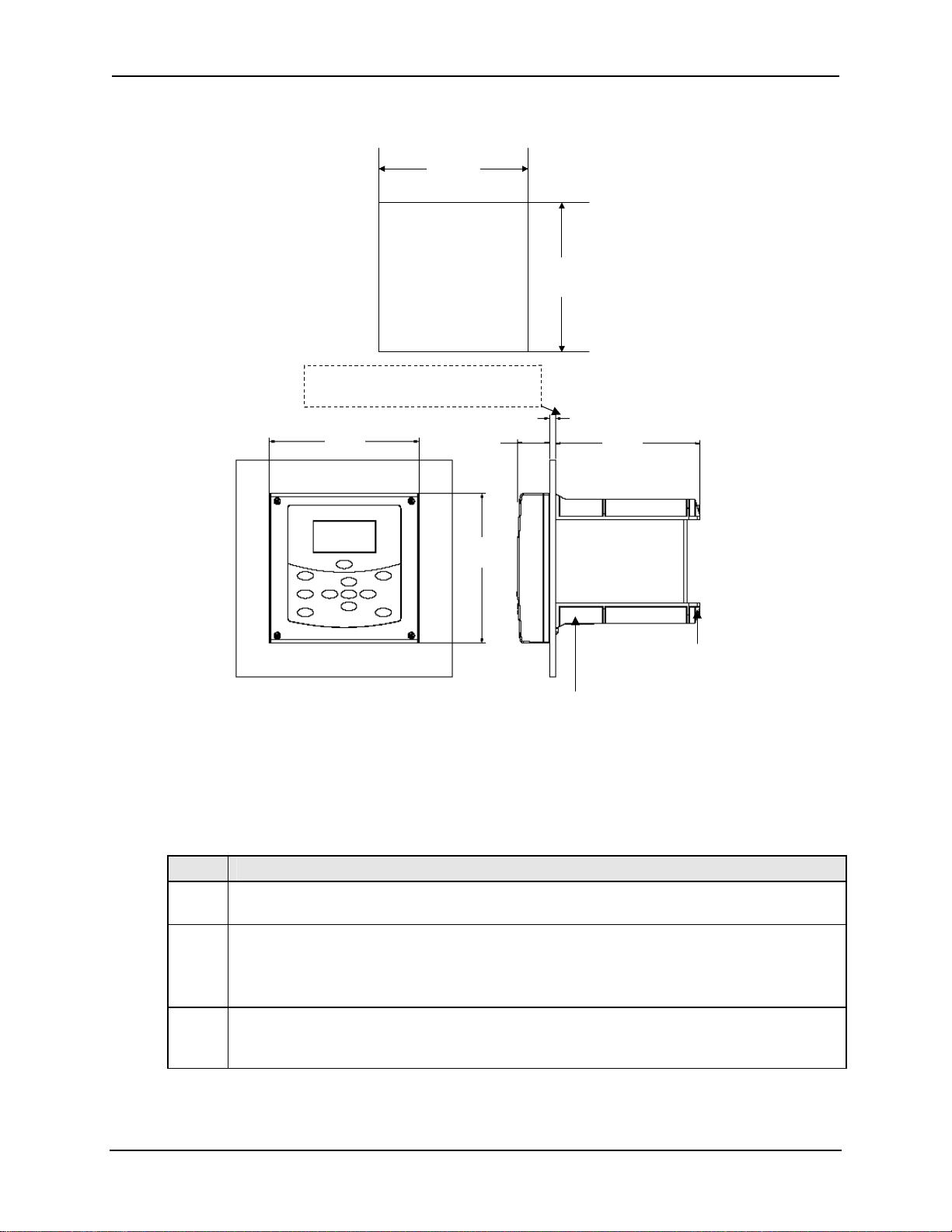
Panel Mounting Dimensions
+1
+1
+1
138
138
138
-0
-0
-0
+.04
+.04
+.04
[5.43]
[5.43]
[5.43]
-0
-0
-0
+1
+1
+1
138
138
138
-0
-0
Panel Cutout
Panel Cutout
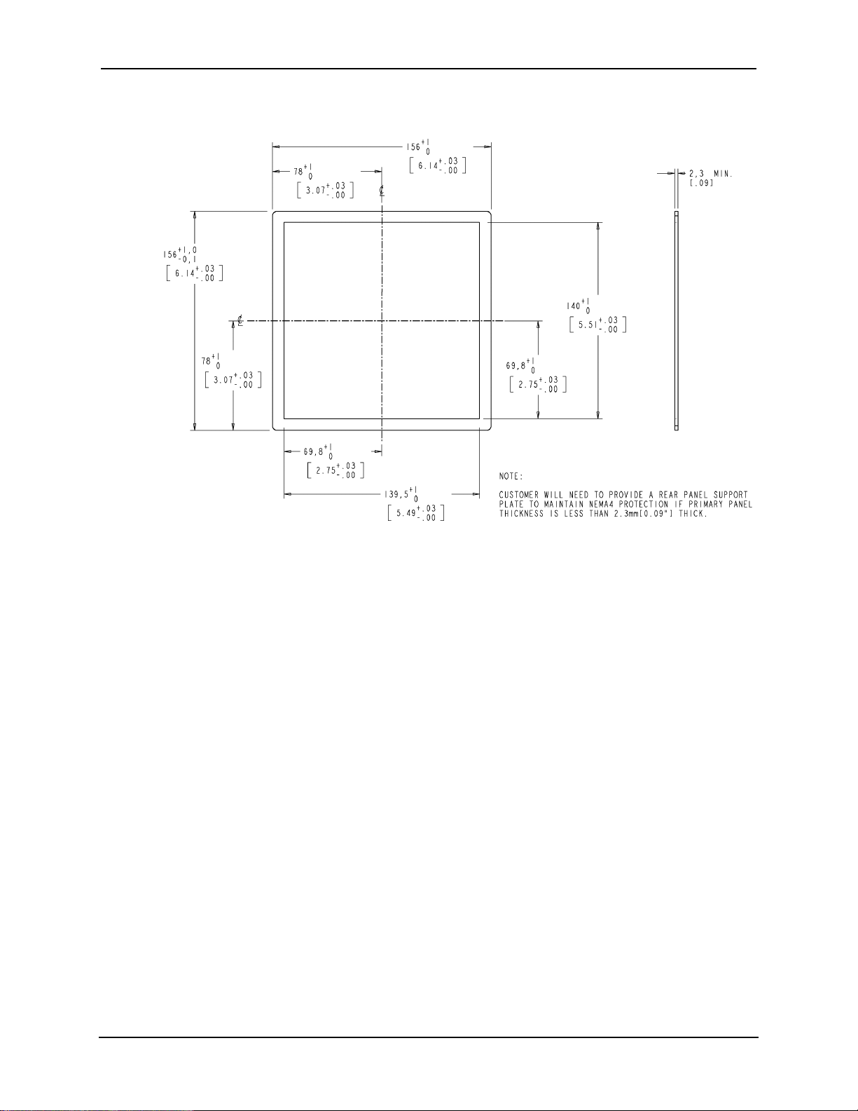
Customer will need to provide a rear panel support
Customer will need to provide a rear panel support
plate to maintain NEMA4 protection if primary
plate to maintain NEMA4 protection if primary
panel thickness is less that 2.3mm [0.09”] thick
panel thickness is less that 2.3mm [0.09”] thick
156
156
[6.14]
[6.14]
33.5
33.5
[1.32]
[1.32]
-0
+.04
+.04
+.04
[5.43]
[5.43]
[5.43]
-0
-0
-0
CUSTOMER PANEL
CUSTOMER PANEL
1.6[.06] to 6.35 MAX[0.25]
1.6[.06] to 6.35 MAX[0.25]
152
152
[5.98]
[5.98]
Figure 3-1 Panel Mounting Dimensions (not to scale)
Panel Mounting Procedure
Table 3-2 Panel Mounting Procedure
Step Action
Mark and cut out the analyzer hole in the panel according to the dimension information
1
in Figure 3-1.
Orient the case properly and slide it through the panel hole from the front.
2
Customer will need to provide a rear panel support plate to maintain NEMA4
protection if primary panel thickness is less that 2.3mm [0.09”] thick –
See Figure 3-2.
Remove the mounting kit from the shipping container and clamp the edges of the
3
cutout between the case flange and the supplied U-bracket that is fastened to the rear
of the case using (2) M5 X 16mm long screws and (2) M5 lock washers supplied.
156
156
[6.14]
[6.14]
(4) 22.22[.87] holes for
(4) 22.22[.87] holes for
lead wires and conduit fittings
lead wires and conduit fittings
(conduit fittings supplied by user)
(conduit fittings supplied by user)
January 2009 UDA2182 Universal Dual Analyzer Product Manual 11
Unpacking
Rear Panel Support Plate Dimensions
Figure 3-2 Rear Panel Support Plate Dimensions
12 UDA2182 Universal Dual Analyzer Product Manual January 2009
Unpacking
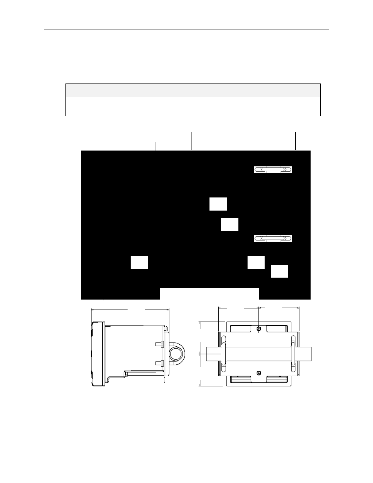
Pipe Mounting
The analyzer can be mounted vertically or horizontally on a pipe. Use the bracket and
hardware supplied in the mounting kit.
Select 1 inch or 2 inch U-Bolts.
ATTENTION
Pipe mounting is not recommended if the pipe is subject to severe vibration. Excessive
vibration may affect system performance.
M5 X 10mm long screw with M5 lock washer (2 places)
M5 X 10mm long screw with M5 lock washer (2 places)
Note orientation of hole and slot in mounting bracket.
Note orientation of hole and slot in mounting bracket.
Hole is to be in the upper position.
M8 Nut
M8 Nut
M8 Lock Washer
M8 Lock Washer
M8 Flat Washer
M8 Flat Washer
Hole is to be in the upper position.
195.1
195.1
[7.68]
[7.68]
Do not over
Do not over
tighten fasteners
tighten fasteners
4.5Nm (40 Lb-in) of
4.5Nm (40 Lb-in) of
torque max.
torque max.
188.1
188.1
[7.40]
[7.40]
188.1
188.1
[7.40]
[7.40]
97.5
97.5
[3.84]
[3.84]
77.4
77.4
[3.05]
[3.05]
1 or 2 inch Vertical Rear Pipe Mounting
1 or 2 inch Vertical Rear Pipe Mounting
97.5
97.5
[3.84]
[3.84]
78
78
[3.07]
[3.07]
78
78
[3.07]
[3.07]
1 or 2 inch Horizontal Rear Pipe Mounting
1 or 2 inch Horizontal Rear Pipe Mounting
97.5
97.5
[3.84]
[3.84]
156
156
[6.14]
[6.14]
Figure 3-3 Pipe Mounting Dimensions (not to scale)
January 2009 UDA2182 Universal Dual Analyzer Product Manual 13
Unpacking
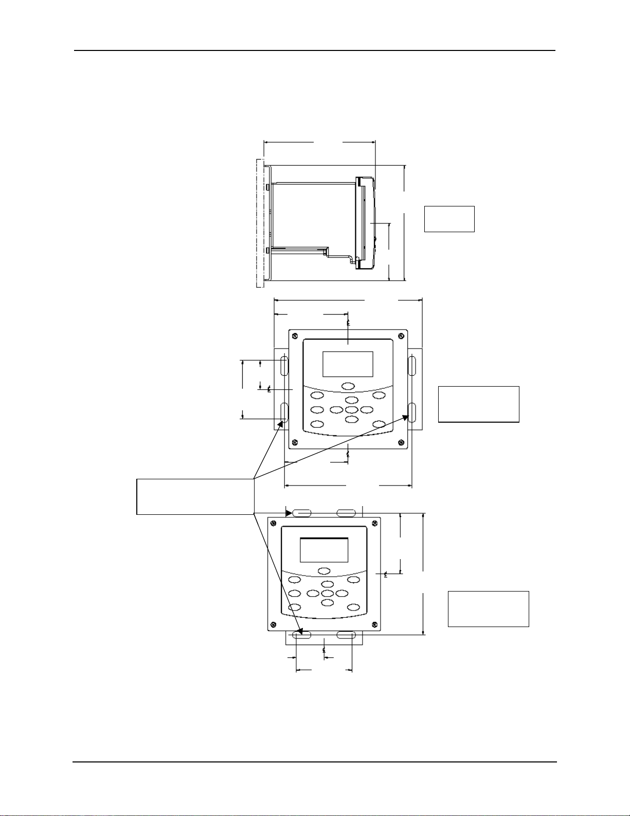
Wall Mounting Dimensions
The analyzer can be mounted on a wall. Use the bracket and hardware supplied in the
mounting kit.
188.1
188.1
[7.40]
[7.40]
195.06
195.06
[7.680]
38.5
38.5
[1.51]
[1.51]
97.5
97.5
[3.84]
[3.84]
195.1
195.1
[7.68]
[7.68]
83.9
83.9
[3.30]
[3.30]
97.53
97.53
[3.840]
[3.840]
195.1
195.1
[7.68]
[7.68]
[7.680]
Left hand
Left hand
Side View
Side View
77
77
[3.03]
[3.03]
Four slots in bracket for
Four slots in bracket for
6.0mm [1/4 “] dia mounting
6.0mm [1/4 “] dia mounting
bolts supplied by customer
bolts supplied by customer
38.5
38.5
[1.52]
[1.52]
83.9
83.9
[3.30]
[3.30]
77
77
[3.03]
[3.03]
167.6
167.6
[6.60]
[6.60]
83.9
83.9
[3.30]
[3.30]
167.8
167.8
[6.61]
[6.61]
Front View
Front View
Mounting Bracket
Mounting Bracket
Horizontal
Horizontal
Front View
Front View
Mounting Bracket
Mounting Bracket
Vertical
Vertical
Figure 3-4 Wall Mounting Dimensions (not to scale)
14 UDA2182 Universal Dual Analyzer Product Manual January 2009
Power Wiring
4 Power Wiring
4.1 Overview
Introduction
This section contains instructions for installing ac power wiring for the Analyzer, in
preparation for performing configuration setup as described in Section 6.
We recommend that you wait to install input and output wiring (See Section 7) until after
Configuration Setup. During configuration the software will determine for you, which
relay to use for each feature.
What’s in this section?
The topics in this section are listed below.
Topic See Page
4.1 Overview 15
4.2 General Wiring Practices 16
4.3 Power Wiring Considerations 17
4.4 Installing Power Wiring 17
January 2009 UDA2182 Universal Dual Analyzer Product Manual 15
Power Wiring
4.2 General Wiring Practices
WARNING
Safety precaution
Qualified personnel should perform wiring only.
WARNING
A disconnect switch must be installed to break all current
carrying conductors. Turn off power before working on
conductors. Failure to observe this precaution may result in
serious personal injury.
WARNING
An external disconnect switch is required for any hazardous
voltage connections to the relay outputs.
Avoid damage to components
ATTENTION
This equipment contains devices that can be damaged by electrostatic discharge (ESD). As
solid-state technology advances and as solid-state devices get smaller and smaller, they
become more and more sensitive to ESD. The damage incurred may not cause the device to
fail completely, but may cause early failure. Therefore, it is imperative that assemblies
containing static sensitive devices be carried in conductive plastic bags. When adjusting or
performing any work on such assemblies, grounded workstations and wrist straps must be
used. If soldering irons are used, they must also be grounded.
A grounded workstation is any conductive or metallic surface connected to an earth ground,
such as a water pipe, with a 1/2 to 1 megohm resistor in series with the ground connection. The
purpose of the resistor is to current limit an electrostatic discharge and to prevent any shock
hazard to the operator. The steps indicated above must be followed to prevent damage and/or
degradation, which may be induced by ESD, to static sensitive devices.
Wiring for immunity compliance
In applications where either the power, input or output wiring are subject to
electromagnetic disturbances, shielding techniques will be required. Grounded metal
conduit with conductive conduit fittings is recommended.
Connect the AC mains through a fused disconnect switch.
Conform to code
Instrument wiring should conform to regulations of the National Electrical Code.
16 UDA2182 Universal Dual Analyzer Product Manual January 2009
Power Wiring
4.3 Power Wiring Considerations
Recommended wire size
Observe all applicable electrical codes when making power connections. Unless locally
applicable codes dictate otherwise, use 14-gauge (2.081 mm
including protective earth.
Power supply voltage and frequency within specs
The power supply voltage and frequency must be within the limits stated in the
specifications in Section 2.
4.4 Installing Power Wiring
Procedure
WARNING
Turn power off at mains before installing AC Power Wiring.
Do not remove boards with power ON.
WARNING
The ground terminal must be connected to a reliable earth
ground for proper operation and to comply with OSHA and
other safety codes. If metal conduit is used, connect a bonding
wire between conduits. Do not rely upon the conductive coating
of the instrument case to provide this connection. Failure to
observe this precaution may result in serious personal injury.
2
) wire for ac power,
CAUTION
To avoid damage to the case when connecting to a rigid metallic conduit system, the
conduit hub must be connected to the conduit before the hub is connected to the
enclosure
Table 4-1 Procedure for installing AC Power Wiring
Step Action
Check the tag on the outside of the case to be sure that the voltage rating of the unit
1
matches the input voltage at your site.
ATTENTION
The Unit may be damaged if you apply power with the wrong voltage.
2 With Power off, open the case:
• Loosen the four captive screws on the front of the bezel.
• Grasp the bezel on the right side. Lift the bezel gently and swing the bezel open to the left.
Refer to Figure 7-1 for the location of the printed wiring board retainer. Loosen the two
3
January 2009 UDA2182 Universal Dual Analyzer Product Manual 17

Power Wiring
Step Action
screws that hold the retainer and slide the retainer to the left until the retainer tabs
disengage from the terminal boards.
Refer to Figure 7-1 for the location of the Power Supply/Analog Output/Relay Output board.
4
Insert a screwdriver into the hole in the middle of the terminal board and pull out gently.
Slide the board half way out. There is a notch in the terminal board into which you can slide
the retainer tabs and hold the board in place while wiring.
Install a fused disconnect switch in the power line that will be connected to the Analyzer.
5
•If a 230/240 Vac line is to be connected, use a 0.15 amp fuse.
•If a 110/120 Vac line is to be connected, use a 0.30 amp fuse.
Fuse must be a Time-Delay or Slo-Blo type.
Each unit has (4) 22.22mm [.87"] dia. holes on the bottom of the unit for lead wires and
6
conduit fittings. Conduit fittings to be supplied by the user.
Feed the power wiring through the wiring port on the bottom of the case. Connect the power
wiring to terminals L1 and L2/N as shown in Figure 4-1. Connect the Green safety ground
wire to the grounding stud on the case.
Attention: Terminal 1 must be connected to the ground stud on the grounding bar using
a #14 AWG UL/CSA-approved wire.
Slide the retainer to the left then slide the terminal board back into place. Slide retainer to
7
engage the tabs and tighten the screws.
Close the Bezel and secure four captive screws to a torque value of .20 Nm (1.5 Lb-in).
8
Power up the unit.
Do not apply power until the bezel is closed.
18 UDA2182 Universal Dual Analyzer Product Manual January 2009
 Loading...