


THX9000
Prestige™Thermostat
With wireless accessories
® U.S. Registered Trademark.
Copyright © 2008 Honeywell International Inc.
All rights reserved.
Control for up to 3 Heat/2 Cool heat pump systems or up to
2 Heat/2 Cool conventional systems.
DISCONNECT POWER BEFORE BEGINNING INSTALLATION. Can cause electrical
shock or equipment damage.
MERCURY NOTICE: If this product is replacing a control that contains mercury in a
sealed tube, do not place the old control in the trash. Contact your local waste
management authority for instructions regarding recycling and proper disposal.
Must be installed by a trained, experienced technician. Read these instructions
carefully. Failure to follow these instructions can damage the product or cause a
hazardous condition.
System
Installation
Guide
Français : voir la page 17 • Español: vea la página 33
Installation guide for:
• THX9000 Prestige HD and Prestige SD thermostats
• Wireless remote control
• Wireless outdoor air sensor
Prestige™ Installation Guide
2
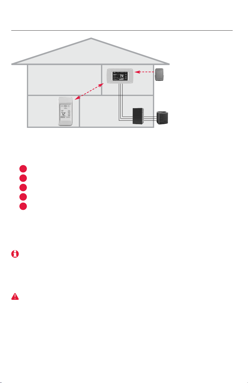
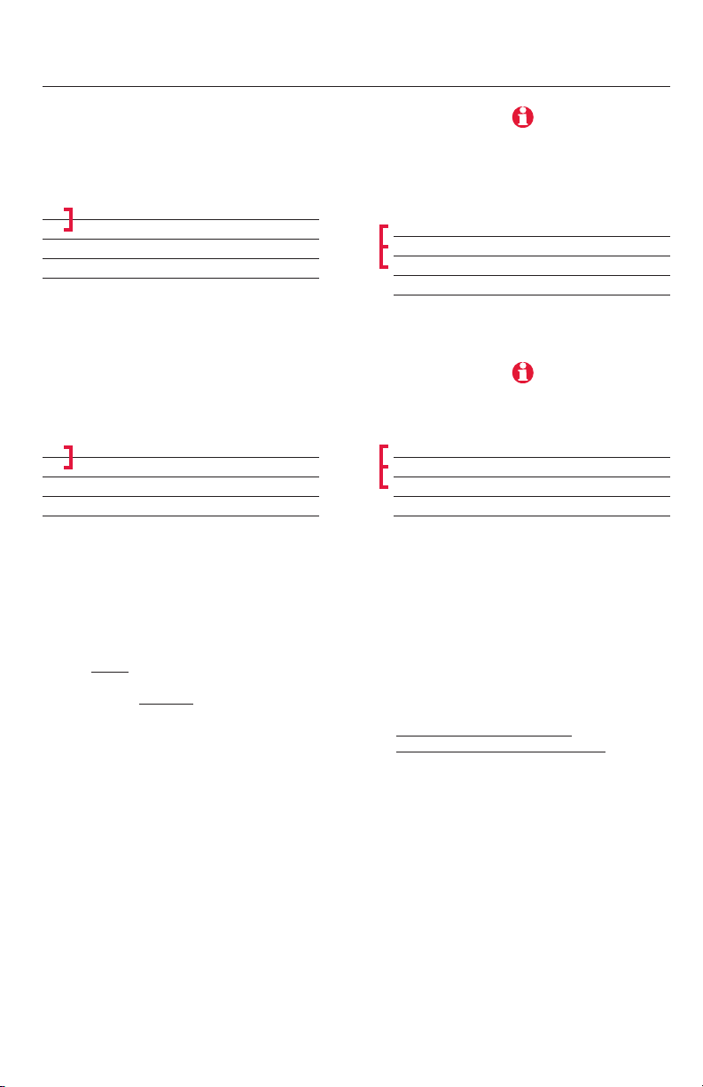
System installation at a glance
Thermostat
Outdoor
air sensor
Remote
control
Installation procedure
Mount and wire thermostat ........................................Pages 3-7
Customize thermostat (installer setup) ............................Page 8
Install batteries in wireless accessories ..........................Page 8
Link accessories to thermostat ................................Pages 9-10
Mount outdoor sensor ....................................................Page 11
To replace system components if needed, see page 14
2
5
4
3
1
DISCONNECT POWER BEFORE BEGINNING INSTALLATION. Can cause electrical
shock or equipment damage.
HVAC equipment
If you have more than one thermostat: Optional accessories must be linked
to each thermostat separately.

Français : voir la page 17 • Español: vea la página 33
3
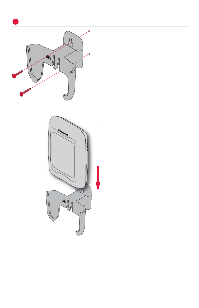
Mount and wire thermostat
1
Pull wiring through hole in wallplate and install as shown below.
Wiring
Wiring must comply with local electrical codes.
Drywall: 3/16” hole
Plaster: 7/32” hole
Wall anchor
Mounting screw
Strip 1/4” insulation and connect wires to screw terminals as shown below
(see wiring guides on following pages).
Factory-installed jumper System wiring
Prestige™ Installation Guide
4
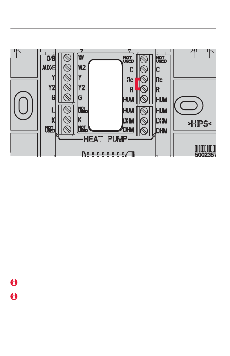
Wiring guide
See detailed wiring guides for specific system types on following pages.
Conventional Terminal Letters:
C Common wire from secondary side of
cooling transformer.
Rc Cooling power. Connect to secondary
side of cooling system transformer.
R Heating power. Connect to secondary
side of heating system transformer.
W Heat relay (stage 1).
W2 Heat relay (stage 2).
Y Compressor contactor (stage 1).
Y2 Compressor contactor (stage 2).
G Fan relay.
K THP9054 connection
(see note below)
Heat Pump Terminal Letters:
C Common wire from secondary side of
cooling system transformer.
Rc Cooling power. Connect to secondary
side of cooling system transformer.
R Heating power. Connect to secondary
side of heating system transformer.
O/B Changeover valve for heat pumps.
Aux/E Auxiliary/Emergency heat relay.
Y Compressor contactor (stage 1).
Y2 Compressor contactor (stage 2).
G Fan relay.
L Heat pump reset (powered continuously
when System is set to Em Heat; system
monitor when set to Heat, Cool or Off).
K THP9054 connection
(see note below)
Note: Use the K terminal in place of the Y and G terminals to provide full fan and compressor control though a single wire. The K terminal must be connected to the THP9045
Wiresaver module (see page 14). The K terminal can not be used in heat-only applications.
Note: Do not connect wires to terminals marked “Not Used.”
Français : voir la page 17 • Español: vea la página 33
5
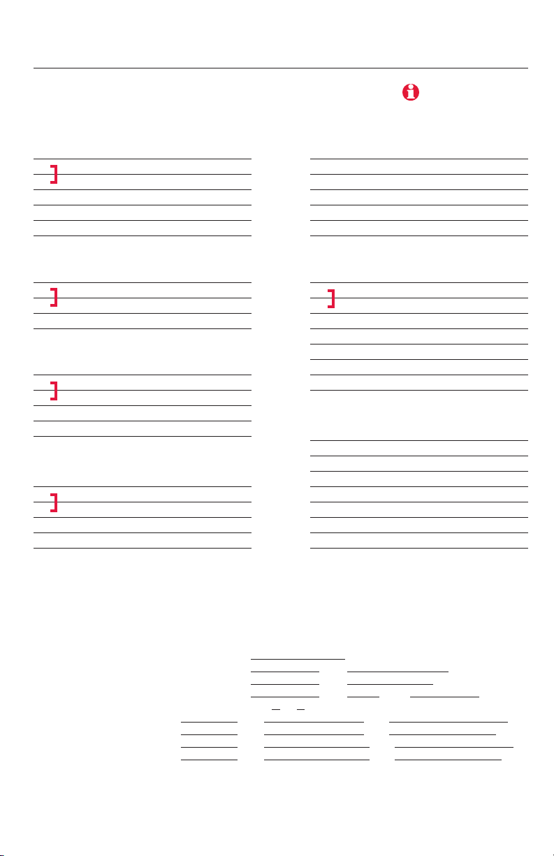
Conventional systems
System-specific wiring guides
1H/1C System (2 transformers)
C 24VAC common
R Power (heating) [1]
Rc Power (cooling) [1, 2]
W Heat relay
Y Compressor contactor **
G Fan relay **
2H/2C System (1 transformer) [6]
C 24VAC common
R Power [1]
Rc [R+Rc joined by jumper]
W Heat relay (stage 1)
W2 Heat relay (stage 2)
Y Compressor contactor (stage 1) **
Y2 Compressor contactor (stage 2)
G Fan relay **
2H/2C System (2 transformers) [6]
C 24VAC common
R Power (heating) [1]
Rc Power (cooling) [1, 2]
W Heat relay (stage 1)
W2 Heat relay (stage 2)
Y Compressor contactor (stage 1) **
Y2 Compressor contactor (stage 2)
G Fan relay **
1H/1C System (1 transformer)
C 24VAC common
R Power [1]
Rc [R+Rc joined by jumper]
W Heat relay
Y Compressor contactor **
G Fan relay **
Heat Only System [3]
C 24VAC common
R Power [1]
Rc [R+Rc joined by jumper]
W Heat relay
Heat Only System With Fan [
4]
C 24VAC common
R Power [1]
Rc [R+Rc joined by jumper]
W Heat relay
G Fan relay
Cool Only System [
5]
C 24VAC common
R Power [1]
Rc [R+Rc joined by jumper]
Y Compressor contactor **
G Fan relay **
See [notes] below.
** [See note on page 4]
[1] Power supply. Provide disconnect means and overload protection as required.
[2] Remove jumper (R to Rc) for systems with two transformers. Common connection
must come from cooling transformer.
[3] In Installer Setup, set system type to Heat Only, No Fan.
[4] In Installer Setup, set system type to Conventional with zero cooling stages.
[5] In Installer Setup, set system type to Conventional with zero heat stages.
[6] In Installer Setup, set system type to Conventional with 2 heat AND 2 cool stages.
[7] In Installer Setup, set changeover valve to O or B.
[8] In Installer Setup, set to Heat Pump with 1 compressor stage and no auxiliary heat stages.
[9] In Installer Setup, set to Heat Pump with 1 compressor stage and 1 auxiliary heat stage.
[10] In Installer Setup, set to Heat Pump with 2 compressor stages and no auxiliary heat stages.
[11] In Installer Setup, set to Heat Pump with 2 compressor stages and 1 auxiliary heat stage.
[12] “L” terminal sends a continuous output when thermostat is set to Em. Heat, and acts
as a system monitor when in Heat, Cool or Off modes.

Prestige™ Installation Guide
6
System-specific wiring guides
Heat pump systems
2H/2C Heat Pump [10]
C 24VAC common
R Power [1]
Rc [R+Rc joined by jumper]
O/B Changeover valve [7]
Y Compressor contactor (stage 1) **
Y2 Compressor contactor (stage 2)
G Fan relay **
3H/2C Heat Pump [11]
C 24VAC common
R Power [1]
Rc [R+Rc joined by jumper]
O/B Changeover valve [7]
Aux Auxiliary heat relay
Y Compressor contactor (stage 1) **
Y2 Compressor contactor (stage 2)
G Fan relay **
L Relay [12]
** [See note on page 4]
[1] Power supply. Provide disconnect means and overload protection as required.
[2] Remove jumper (R to Rc) for systems with two transformers. Common connection
must come from cooling transformer.
[3] In Installer Setup, set system type to Heat Only, No Fan.
[4] In Installer Setup, set system type to Conventional with zero cooling stages.
[5] In Installer Setup, set system type to Conventional with zero heat stages.
[6] In Installer Setup, set system type to Conventional with 2 heat AND 2 cool stages.
[7] In Installer Setup, set changeover valve to O or B.
[8] In Installer Setup, set to Heat Pump with 1 compressor stage and no auxiliary heat stages.
[9] In Installer Setup, set to Heat Pump with 1 compressor stage and 1 auxiliary heat stage.
[10] In Installer Setup, set to Heat Pump with 2 compressor stages and no auxiliary heat stages.
[11] In Installer Setup, set to Heat Pump with 2 compressor stages and 1 auxiliary heat stage.
[12] “L” terminal sends a continuous output when thermostat is set to Em. Heat, and acts
as a system monitor when in Heat, Cool or Off modes.
1H/1C Heat Pump [8]
C 24VAC common
R Power [1]
Rc [R+Rc joined by jumper]
O/B Changeover valve [7]
Y Compressor contactor **
G Fan relay **
2H/1C Heat Pump [9]
C 24VAC common
R Power [1]
Rc [R+Rc joined by jumper]
O/B Changeover valve [7]
Aux Auxiliary heat relay
Y Compressor contactor **
G Fan relay **
L Relay [12]
See [notes] below.
Français : voir la page 17 • Español: vea la página 33
7
System-specific wiring guides
Humidification systems
Bypass, flow-through humidifier (or
any humidifier that uses the system
transformer) [3]
Rc Power [1]
R [R+Rc joined by jumper] [2]
HUM1 Field jumper R to HUM 1 [5]
HUM2 Humidifier relay [5]
[1] Power supply. Provide disconnect means and overload protection as required.
[2] Remove jumper (R to Rc) for systems with two transformers. Common connection
must come from cooling transformer.
[3] If using a humidifier that is wired directly to the thermostat, set humidification control
to Wired in Installer Setup.
[4] If using a wireless adapter (THM4000R) with a TrueSTEAM humidifier, set humidification
control to Wireless in Installer Setup. Connect nothing to thermostat HUM terminals.
[5] Terminals are normally open dry contacts.
[6] In Installer Setup, set dehumidification setting to Whole House Dehumidifier.
[7] In Installer Setup, set dehumidification setting to Dehumidify with Air Conditioner.
[8] Terminals are normally closed dry contacts.
[9] Equipment must include dehumidification terminal for low-speed fan.
Steam humidifier (or any humidifier with
its own transformer) [3, 4]
Rc Power [1]
R [R+Rc joined by jumper] [2]
HUM1 Humidifier relay [5]
HUM2 Humidifier relay [5]
See [notes] below.
Dehumidification systems
A/C with low-speed fan [7]
Rc Power [1]
R [R+Rc joined by jumper] [2]
DHM1 Field jumper Rc to DHM 1 [8]
DHM2 Dehumidifier relay [8, 9]
Whole house dehumidifier [6]
Rc Power [1]
R [R+Rc joined by jumper] [2]
DHM1 Dehumidifier relay [5]
DHM2 Dehumidifier relay [5]
See [notes] below.
8
Prestige™ Installation Guide
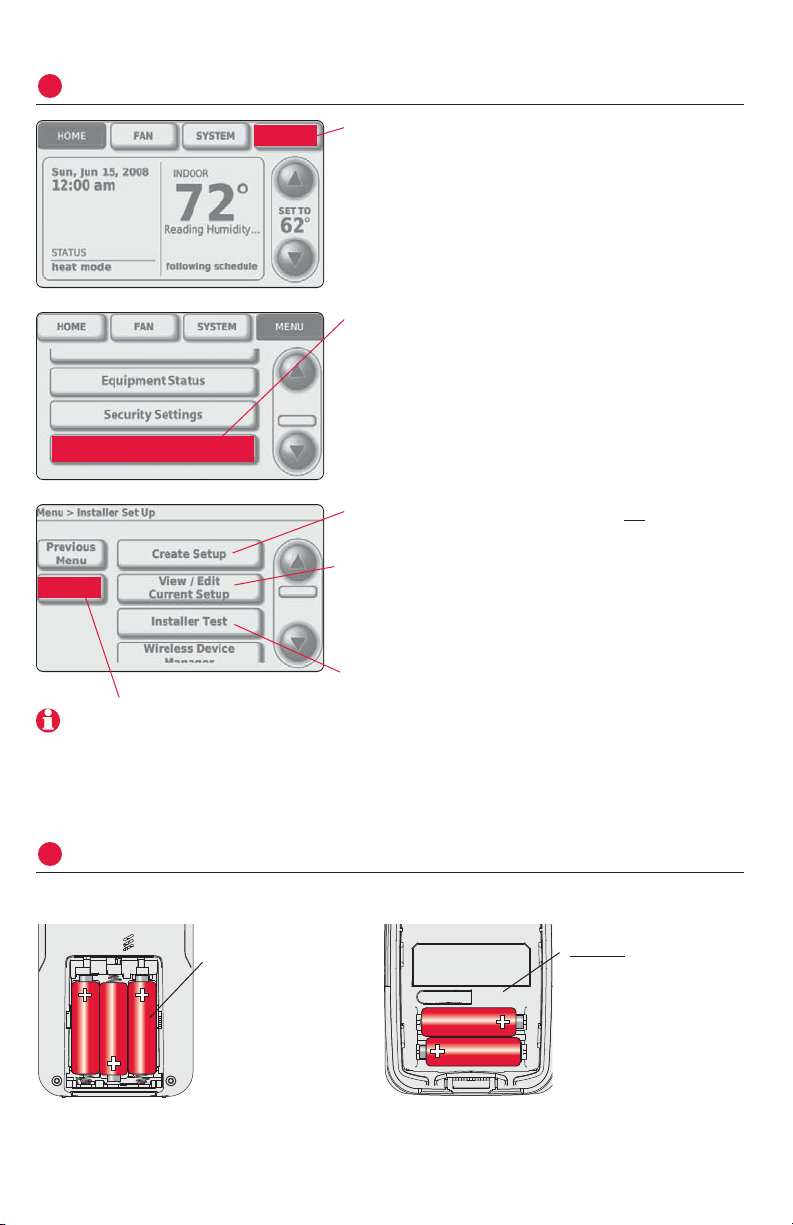
Press
MENU
.
Customize thermostat (installer options)
2
MENU
Press ▼ to scroll down, then press
INSTALLER
OPTIONS
. Enter security code when prompted.
Security code is the thermostat date code
(printed on back of wallplate). Or press
MENU> EQUIPMENT STATUS
to find code.
Installer Options
Press
CREATE SETUP
to configure all system
settings one by one.
Press
VIEW/EDIT
to select a specific function
and make quick changes. (See complete
list of system settings on pages 12-13.)
Press
INSTALLER TEST
to run system tests. You
should always test the system after
making changes to settings.
Note: Press
HELP
for more
information on these and
other options.
Install batteries in wireless accessories
3
Remote control (optional) Outdoor air sensor (optional)
Install 3 fresh AA
batteries
Install 2 fresh AA
lithium batteries
HELP
9
Français : voir la page 17 • Español: vea la página 33
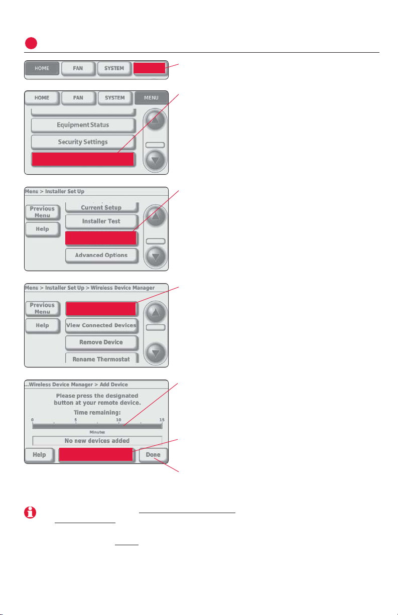
Press
MENU
.
Link wireless accessories to thermostat (optional)
4
MENU
Press ▼ to scroll down, then press
INSTALLER
OPTIONS
. Enter security code when prompted.
Security code is the thermostat date code
(printed on back of wallplate). Or press
MENU> EQUIPMENT STATUS
to find code.
Installer Options
Press ▼ to scroll down, then press
WIRELESS
DEVICE MANAGER
.
Wireless Device
Manager
Press
ADD DEVICE
to start timer, then press
buttons on wireless accessories to link
them to the thermostat (see next page).
Add Device
Timer will re-set to 15 minutes after each
accessory is linked. Thermostat will exit
link mode after 15 minutes if there is no
activity.
Press
VIEW CONNECTED DEVICES
to verify that all
wireless accessories have been linked to
the thermostat
Press
DONE
when finished.
Note: If you are installing more than one thermostat, repeat steps above and on page 10
for each thermostat.
If you are installing multiple thermostats, you must press
DONE to exit “Add Device” mode
at each thermostat before
linking wireless accessories to the next thermostat.
View Connected Devices
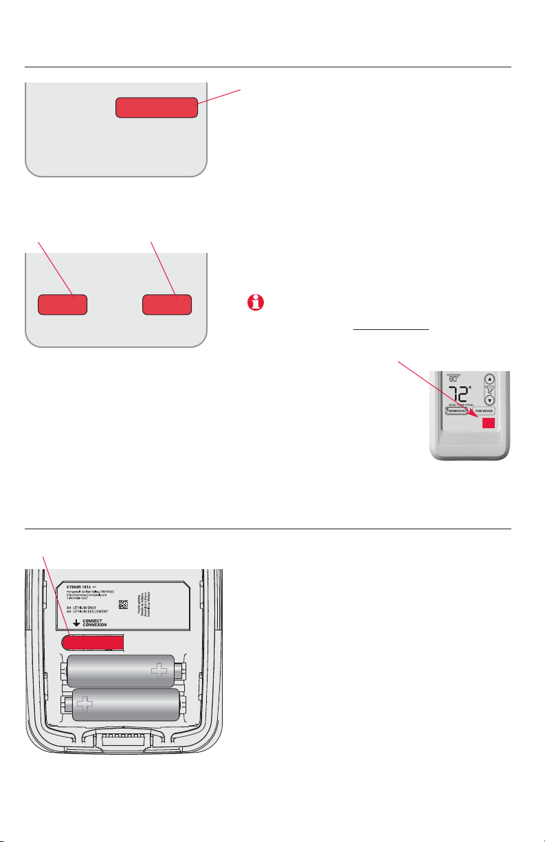
Link remote control to thermostat (optional)
1 Make sure the thermostat displays
the “Add Device” timer (see page 9).
2 Press
CONNECT
at the remote. There will
be a short delay as the remote seeks
a signal from the thermostat.
3 When the screen displays
“Connected,” press
DONE
.
4 Press NOat the next screen to save
and exit. (Or press
YES
and repeat
steps 1-4 to link another thermostat.)
WIRELESS SETUP
CONNECT
Link outdoor sensor to thermostat (optional)
1 Make sure the thermostat displays
the “Add Device” timer (see page 9).
2 Press the
CONNECT
button on the back
of the sensor.
3 Check thermostat to verify that the
outdoor sensor is working. After
about 15 seconds, the thermostat
should display outdoor temperature
and humidity.
Press and release
10
Prestige™ Installation Guide
YES NO
CONNECT MORE?
The linking procedure at the remote may time
out if there is no keypress within 30 minutes.
To begin again, press and hold the blank
space (or arrow if present) in the lower right
corner of the screen until the display changes
(about 3 seconds).
Press to link to
another thermostat
Press to save
and exit
11
Français : voir la page 17 • Español: vea la página 33
Place sensor securely in bracket,
facing away from wall
Mount the sensor on a vertical exterior
wall, at least 6 inches below any overhang. Choose a location protected
from direct sunlight.
Install outdoor sensor (optional)
5

Installer setup tables
12
Prestige™ Installation Guide
Setup functions (factory default setting listed, other options available)
100 Language English
110 Zone number Not zoned
112 Device name Thermostat
130 Date year 2008
140 Date month June
150 Date day 15
160 Schedule options Programmable
165 Restore Energy Star No
172 System selection Conventional
174 Compressor stages 1
176 Heat stages 1
180 Fan operation System (gas/oil/heat)
190 Reversing valve O/B on Cool
200 Backup heat Electric
210 External fossil fuel Yes
220 Compressor stage 1 cycle rate 3
230 Compressor stage 2 cycle rate 3
240 Heat stage 1 cycle rate (Aux) 5
250 Heat stage 2 cycle rate (Aux 2) 5
260 Heat stage 3 cycle rate 5
281 Display inactive backlight level 5 (color models only)
285 Display contrast 5 (grayscale models only)
300 Changeover Manual
310 Deadband 2° F
320 Temperature display Fahrenheit
330 Daylight savings time Auto change: On
342 Outdoor temperature sensor? No
345 Dual-fuel heat pump control Balance point + droop
346 Dual-fuel upstage timer 60 minutes
350 Compressor lockout (balance point) Off
360 Auxiliary lockout Off
365 Discharge temperature sensor? No
366 Zoning discharge high limit 160° F (71° C)
367 Zoning discharge low limit 40° F (4.5° C)
368 Staging discharge high limit 110° F (43.5° C)
369 Staging discharge low limit 55° F (13.0° C)
371 Humidification equipment None
372 Indoor humidity control Off
374 Humidifier fan action Humidify only with fan
379 Dehumidification equipment None
380 Indoor dehumidification control None
383 Overcooling limit 3° F (1.5° C)

13
Français : voir la page 17 • Español: vea la página 33
Setup functions (factory default setting listed, other options available)
384 Dehumidification fan control Forces fan on
390 Dehumidification away mode Off
391 Away mode fan operation Automatic
392 Away mode low temp. setting 76° F (24.5° C)
393 Away mode high temp. setting 85° F (29.5° C)
394 Away mode dehumidification 65% relative humidity
500 Reminder: Furnace filter Off
502 Furnace filter runtime counter Count heat and cool
510 Reminder: Humidifier pad Off
520 Reminder: UV bulb Off
530 Adaptive Intelligent Recovery On
540 Number of schedule periods 4
580 Minimum compressor off time 5 minutes
600 Maximum heat range 90° F (32° C)
610 Minimum cool range 60° F (15.5° C)
630 Minimum compressor off time Off
640 Clock format 12-hour
650 Extended fan on time (heat) Off
660 Extended fan on time (cool) Off
670 Keypad lock Unlocked
680 Temp. control (heat) Standard
690 Temp. control (cool) Standard
700 Temperature display offset No offset
701 Humidity display offset No offset
702 Outdoor temp. display offset No offset
703 Outdoor humidity display offset No offset
710 RESTORE FACTORY DEFAULTS No
Customer contact information (optional, but recommended)
1100 Dealer name Your company name
1150 Dealer phone number Your telephone contact
1200 Dealer email address Your email address
1250 Dealer website Your web site
Installer setup tables
14
Prestige™ Installation Guide
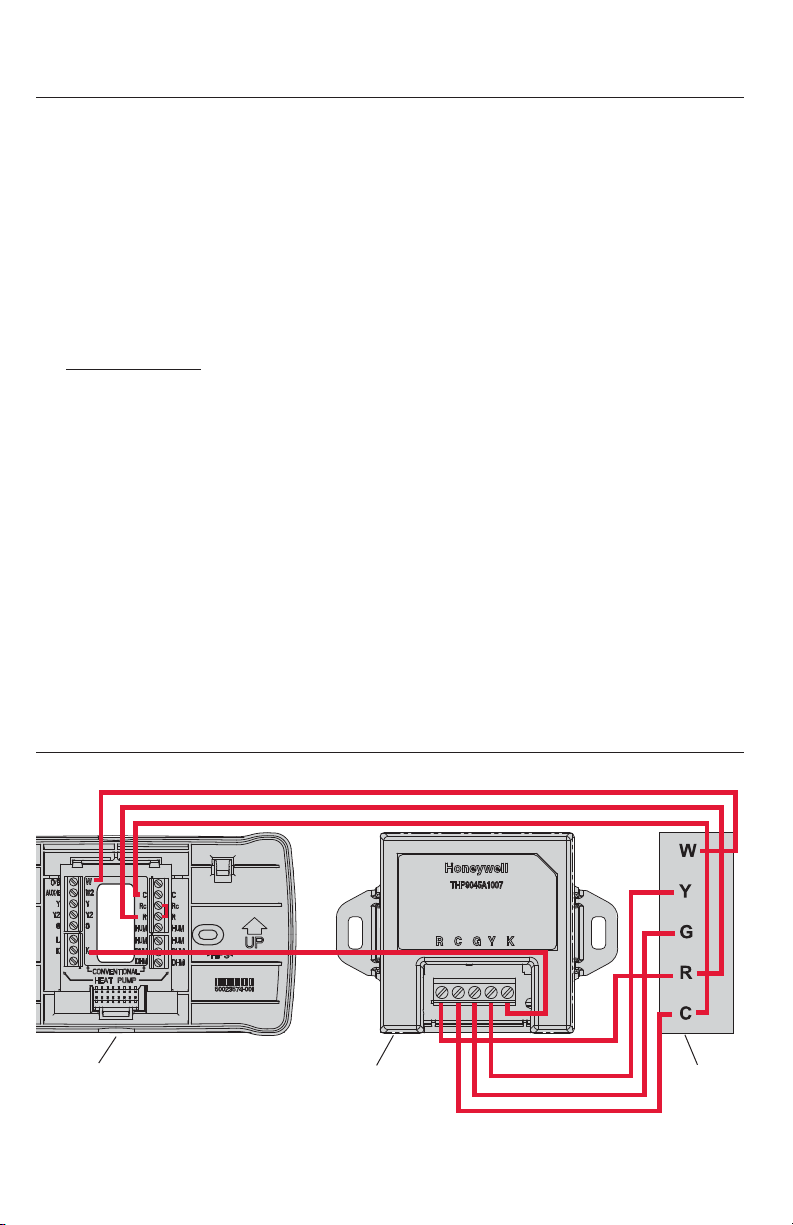
Replacing system components
THP9045 Wiresaver installation guide
W
R
C
K
R
Y
G
C
Thermostat THP9045
Wiresaver
HVAC
equipment
Thermostat
After installing a new thermostat, you must re-link all accessories to the
new thermostat, as described below.
1 Install and wire new thermostat (see pages 3-7)
2 Customize new thermostat (see page 8)
3 Link wireless accessories (see pages 9-10)
At the remote control:
• Press and hold
the blank space (or arrow if present) in the lower right
corner of the screen until the display changes (see page 10).
• Press
REMOVE
, then
YES
to disconnect from old thermostat.
• Follow the procedure on page 10 to link to new thermostat.
At the outdoor air sensor:
• Press the
CONNECT
button to link to the new thermostat (see page 10).
4 Press
DONE
at the thermostat.
Remote control & outdoor sensor
To replace a remote control or outdoor air sensor, install batteries and
follow the procedures on pages 9-10 to link it to the thermostat.

15
Français : voir la page 17 • Español: vea la página 33
Specifications & replacement parts
Operating Ambient Temperature
Thermostat: 32 to 120° F (0 to 48.9° C)
Remote control: 32 to 120° F (0 to 48.9° C)
Outdoor air sensor: -40 to 140° F (-40 to 60° C)
Operating Relative Humidity
Thermostat: 5% to 90% (non-condensing)
Remote control: 5% to 90% (non-condensing)
Outdoor air sensor: 0% to 100% (condensing)
Physical Dimensions (height, width, depth)
Thermostat: 3-9/16 x 5-13/16 x 1-1/2 inches (91 x 147 x 38 mm)
Outdoor air sensor: 5 x 3-1/2 x 1-11/16 inches (127 x 89 x 43 mm)
Electrical Ratings
Terminal Voltage (50/60 Hz) Max. Current Rating
W (heating) 18 to 30 VAC 1.00A
Y (cooling) 18 to 30 VAC 1.00A
G (fan) 18 to 30 VAC 0.60A
O/B (changeover) 18 to 30 VAC 0.60A
W2 (heating) 18 to 30 VAC 0.60A
Y2 (cooling) 18 to 30 VAC 0.60A
Aux/E (Auxiliary) 18 to 30 VAC 1.00A
L (Output) 18 to 30 VAC 0.60A
K N/A N/A
HUM 1 (humidifier) 30 VAC max. 0.50A
HUM 2 (humidifier) 30 VAC max. 0.50A
DHM 1 (dehumidifier) 30 VAC max. 0.50A
DHM 2 (dehumidifier) 30 VAC max. 0.50A
Accessories & Replacement Parts
Item Part Number
Wireless adapter THM4000R1000
Remote control REM5000R1001
Outdoor air sensor C7089R1013
Cover plate (covers marks left by old thermostats) 50028399-001
Wire saving module THP9045A1007

16
Prestige™ Installation Guide
Regulatory information
FCC Compliance Statement (Part 15.19) (USA only)
This device complies with Part 15 of the FCC Rules. Operation is subject to the following two
conditions:
1 This device may not cause harmful interference, and
2 This device must accept any interference received, including interference that may cause
undesired operation.
FCC Warning (Part 15.21) (USA only)
Changes or modifications not expressly approved by the party responsible for compliance
could void the user’s authority to operate the equipment.
FCC Interference Statement (Part 15.105 (b)) (USA only)
This equipment has been tested and found to comply with the limits for a Class B digital
device, pursuant to Part 15 of the FCC Rules. These limits are designed to provide reasonable
protection against harmful interference in a residential installation. This equipment generates
uses and can radiate radio frequency energy and, if not installed and used in accordance with
the instructions, may cause harmful interference to radio communications. However, there is no
guarantee that interference will not occur in a particular installation. If this equipment does
cause harmful interference to radio or television reception, which can be determined by turning
the equipment off and on, the user is encouraged to try to correct the interference by one of
the following measures:
• Reorient or relocate the receiving antenna.
• Increase the separation between the equipment and receiver.
• Connect the equipment into an outlet on a circuit different from that to which the receiver is
connected.
• Consult the dealer or an experienced radio/TV technician for help.
Thermostats and outdoor sensor
To comply with FCC and Industry Canada RF exposure limits for general population/ uncontrolled exposure, the antenna(s) used for these transmitters must be installed to provide a separation distance of at least 20 cm from all persons and must not be co-located or operating in
conjunction with any other antenna or transmitter.
Remote control
This portable transmitter with its antenna complies with FCC and Industry Canada RF
exposure limits for general population/uncontrolled exposure.
Section 7.1.5 of RSS-GEN
Operation is subject to the following two conditions:
1 this device may not cause interference, and
2 this device must accept any interference, including interference that may cause undesired
operation of the device.
 Loading...