


 Loading...
TH8110U Touch Screen
Programmable Thermostats
INSTALLATION INSTRUCTIONS
APPLICATION
The TH8110U Universal Programmable Thermostats provide electronic control of 24 Vac heating and cooling systems or 750 mV heating system. See Table 1 for a general description.
Table 1. TH811 Thermostats Description.
|
|
|
|
|
|
Model |
Power |
Changeover |
System Selection |
Fan Selection |
Comments |
Method |
|||||
|
|
|
|
|
|
|
|
|
|
|
|
TH8110U |
Batteries or |
Automatic or |
Heat-Off-Cool-Auto |
On-Auto-Circ |
System and Fan |
|
common wire |
manual |
|
|
selection vary based on |
|
|
selectable |
|
|
system type |
|
|
|
|
|
|
 RECYCLE NOTICE
If this control is replacing a control that contains mercury in a sealed tube, do not place your old control in the trash. Dispose of properly.
Contact your local waste management authority for instructions regarding recycling and the proper disposal of the old control.
INSTALLATION
When Installing this Product...
1.Read these instructions carefully. Failure to follow the instructions can damage the product or cause a hazardous condition.
2.Check the ratings given in the instructions to make sure the product is suitable for your application.
3.Installer must be a trained, experienced service technician.
4.After completing installation, use these instructions to check out the product operation.
Selecting Location
Install the thermostat about 5 ft. (1.5m) above the floor in an area with good air circulation at average temperature. See Fig. 1.
NO
|
YES |
|
NO |
NO |
5 FEET |
[1.5 METERS]
M19925
Fig. 1. Selecting thermostat location.
Do not install the thermostat where it can be affected by:
—Drafts or dead spots behind doors and in corners.
—Hot or cold air from ducts.
—Radiant heat from sun or appliances.
—Concealed pipes and chimneys.
—Unheated (uncooled) areas such as an outside wall behind the thermostat.
® U.S. Registered Trademark |
|
|
|
|
|
|
|
|
|
|
|
|
|
|
|
|
|
|
|
|
Copyright © 2004 Honeywell International Inc. • |
• All Rights Reserved |
69-1700 |
||||||||||||||||||
|
|
|||||||||||||||||||
TH8110U TOUCH SCREEN PROGRAMMABLE THERMOSTATS
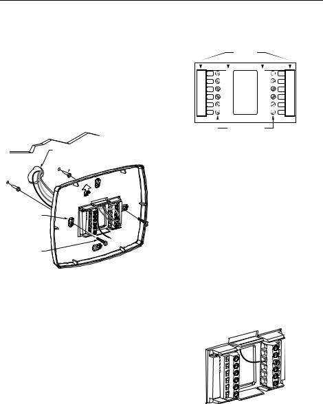
Installing Wallplate
 CAUTION
Electrical Hazard.
Can cause electrical shock or equipment damage.
Disconnect power before wiring.
The thermostat can be mounted horizontally on the wall or on a 4 in. x 2 in. (101.6 mm x 50.8 mm) wiring box.
1.Position and level the wallplate (for appearance only).
2.Use a pencil to mark the mounting holes.
WALL
WIRES THROUGH WALL
AND WIRE SLOT
 WALL ANCHORS (2)
MOUNTING
HOLES
MOUNTING
SCREWS (2)
M19916
Fig. 2. Mounting wallplate.
3.Remove the wallplate from the wall and, if drywall, drill two 3/16-in. holes in the wall, as marked. For firmer material such as plaster, drill two 7/32-in. holes. Gently tap anchors (provided) into the drilled holes until flush with the wall.
4.Position the wallplate over the holes, pulling wires through the wiring opening. See Fig. 2.
5.Insert the mounting screws into the holes and tighten.
WIRING (FIG. 5-11)
All wiring must comply with local electrical codes and ordinances.
1.Select set of terminal identifications (Table 2) that corresponds with system type (conventional or heat pump) in Fig. 3.
2.Loosen the screws for the appropriate system type selected; see Table 2. Insert wires in the terminal block under the loosened screw. See Fig. 4.
3.Securely tighten each screw.
4.Push excess wire back into the hole.
5.Plug the hole with nonflammable insulation to prevent drafts from affecting the thermostat.
HEAT PUMP
 CONVENTIONAL
Y2 |
Y2 |
RC |
RC |
L |
|
R |
R |
E |
|
W |
O/B |
AUX |
W2 |
Y |
Y |
S1 |
S1 |
G |
G |
S2 |
S2 |
C |
C |
|
SCREW TERMINALS |
M19951 |
|
Fig. 3. Selecting terminal identifications for system type.
Table 2. Selecting Terminal Identifications for System Type.
|
|
|
|
Wallplate |
Wiring |
System Type |
Terminal |
Diagram |
Identifications |
Reference |
|
|
|
|
Standard Heat/Cool |
Conventional |
5, 6 |
|
|
|
Heat Only |
Conventional |
7 |
|
|
|
Heat Only with Fan |
Conventional |
8 |
|
|
|
Heat Only Series 20 |
Conventional |
9 |
|
|
|
Cool Only |
Conventional |
10 |
|
|
|
Heat Pump with No |
Heat Pump |
11 |
Auxiliary Heat |
|
|
|
|
|
M19917
Fig. 4. Inserting wires in terminal block.
IMPORTANT
Use 18 gauge thermostat wire.
69-1700 |
2 |

TH8110U TOUCH SCREEN PROGRAMMABLE THERMOSTATS
|
|
CONVENTIONAL |
|
Y2 |
RC |
2 |
|
|
R |
1 |
|
|
|
||
|
W |
|
R |
W2 |
Y |
|
C |
S1 |
G |
|
|
S2 |
C |
OPTIONAL |
|
|
|
24 VAC |
|
|
|
COMMON |
|
|
|
CONNECTION |
|
3 |
|
FAN |
|
OUTDOOR/INDOOR |
|
RELAY |
|
|
|
|
|
TEMPERATURE |
|
COMPRESSOR |
|
SENSOR |
|
|
|
|
CONTACTOR |
|
|
|
|
|
HEAT RELAY
1POWER SUPPLY. PROVIDE DISCONNECT MEANS AND OVERLOAD PROTECTION AS REQUIRED.
2FACTORY INSTALLED JUMPER.
3OPTIONAL OUTDOOR OR INDOOR REMOTE SENSOR. AVAILABLE ON SELECT MODELS. WIRES MUST HAVE A CABLE SEPARATE
FROM THE THERMOSTAT CABLE. |
M19895 |
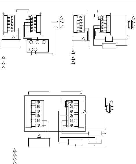
Fig. 5. Typical hookup of conventional single-stage heat and cool system with single transformer (1H/1C conventional).
|
|
CONVENTIONAL |
|
Y2 |
RC |
2 |
|
|
R |
1 |
|
|
|
||
|
W |
|
R |
W2 |
Y |
|
C |
S1 |
G |
|
|
S2 |
C |
OPTIONAL |
|
|
|
24 VAC |
|
|
|
COMMON |
|
|
|
CONNECTION |
|
3 |
|
FAN |
|
OUTDOOR/INDOOR |
|
RELAY |
|
|
|
|
|
TEMPERATURE |
|
COMPRESSOR |
|
SENSOR |
|
|
|
|
CONTACTOR |
1 |
|
|
|
||
|
|
HEAT RELAY |
C |
|
|
|
|
|
|
|
R |
1POWER SUPPLY. PROVIDE DISCONNECT MEANS AND OVERLOAD PROTECTION AS REQUIRED.
2REMOVE FACTORY INSTALLED JUMPER.
3OPTIONAL OUTDOOR OR INDOOR REMOTE SENSOR. AVAILABLE ON SELECT MODELS. WIRES MUST HAVE A CABLE SEPARATE
FROM THE THERMOSTAT CABLE. |
M19896 |
Fig. 6. Typical hookup of conventional single-stage heat and cool system with two transformers (1H/1C conventional).
|
|
CONVENTIONAL |
|
Y2 |
RC |
2 |
|
|
R |
1 |
|
|
|
||
|
W |
|
R |
W2 |
Y |
|
C |
S1 |
G |
|
|
S2 |
C |
OPTIONAL |
|
|
|
24 VAC |
|
|
|
COMMON |
|
|
|
CONNECTION |
|
3 |
|
HEAT RELAY |
|
|
|
|
|
OUTDOOR/INDOOR |
|
|
|
TEMPERATURE |
|
|
|
SENSOR |
|
|
|
1 POWER SUPPLY. PROVIDE DISCONNECT MEANS AND OVERLOAD PROTECTION AS REQUIRED.
2 FACTORY INSTALLED JUMPER.
3 OPTIONAL OUTDOOR OR INDOOR REMOTE SENSOR. AVAILABLE ON SELECT MODELS. WIRES MUST HAVE A CABLE SEPARATE
FROM THE THERMOSTAT CABLE.
M19897
Fig. 7. Typical hookup of heat-only system (1H conventional).
|
|
CONVENTIONAL |
|
Y2 |
RC |
2 |
|
|
R |
1 |
|
|
|
||
|
W |
|
R |
W2 |
Y |
|
C |
S1 |
G |
|
|
S2 |
C |
OPTIONAL |
|
|
|
24 VAC |
|
|
|
COMMON |
|
|
|
CONNECTION |
|
3 |
|
FAN |
|
OUTDOOR/INDOOR |
|
RELAY |
|
|
|
|
|
TEMPERATURE |
|
|
|
SENSOR |
|
HEAT RELAY |
|
1 POWER SUPPLY. PROVIDE DISCONNECT MEANS AND OVERLOAD PROTECTION AS REQUIRED.
2 FACTORY INSTALLED JUMPER.
3 OPTIONAL OUTDOOR OR INDOOR REMOTE SENSOR. AVAILABLE ON SELECT MODELS. WIRES MUST HAVE A CABLE SEPARATE
FROM THE THERMOSTAT CABLE.
M19898
Fig. 8. Typical hookup of heat only system with fan (1H conventional).
3 |
69-1700 |
TH8110U TOUCH SCREEN PROGRAMMABLE THERMOSTATS
|
|
CONVENTIONAL |
||
Y2 |
RC |
2 |
|
|
|
R |
|
1 |
|
|
|
|
||
|
W |
|
|
R |
W2 |
Y |
|
|
C |
S1 |
G |
|
|
|
S2 |
C |
|
|
|
3 |
|
|
|
|
OUTDOOR/INDOOR |
|
W |
B |
R |
TEMPERATURE |
|
|||
|
|
|
|
|
SENSOR |
|
|
|
SERIES 20 |
|
|
|
|
|
|
|
|
MOTOR OR |
|
|
|
TR |
TR |
VALVE |
1POWER SUPPLY. PROVIDE DISCONNECT MEANS AND OVERLOAD PROTECTION AS REQUIRED.
2FACTORY INSTALLED JUMPER.
3OPTIONAL OUTDOOR OR INDOOR REMOTE SENSOR. AVAILABLE ON SELECT MODELS. WIRES MUST HAVE A CABLE SEPARATE FROM THE THERMOSTAT CABLE.
M19899
|
|
CONVENTIONAL |
|
Y2 |
RC |
2 |
|
|
R |
1 |
|
|
|
||
|
W |
|
R |
W2 |
Y |
|
C |
S1 |
G |
|
|
S2 |
C |
OPTIONAL |
|
|
|
24 VAC |
|
|
|
COMMON |
|
|
|
CONNECTION |
|
3 |
|
FAN |
|
|
RELAY |
|
|
|
|
|
|
OUTDOOR/INDOOR |
|
|
|
TEMPERATURE |
|
COMPRESSOR |
|
SENSOR |
|
CONTACTOR |
|
1 POWER SUPPLY. PROVIDE DISCONNECT MEANS AND OVERLOAD PROTECTION AS REQUIRED.
2 FACTORY INSTALLED JUMPER.
3 OPTIONAL OUTDOOR OR INDOOR REMOTE SENSOR. AVAILABLE ON SELECT MODELS. WIRES MUST HAVE A CABLE SEPARATE
FROM THE THERMOSTAT CABLE.
M19900
|
Fig. 10. Typical hookup of cool only system |
Fig. 9. Typical hookup of heat only Series 20 system. |
(1C conventional). |
|
|
HEAT PUMP |
|
|
Y2 |
RC |
1 |
|
|
2 |
R |
|
L |
R |
||
C |
|||
|
|
||
E |
O/B 3 |
|
|
AUX |
Y |
|
|
S1 |
G |
OPTIONAL |
|
|
|
||
S2 |
C |
24 VAC |
|
COMMON |
|||
|
|
CONNECTION |
|
|
|
FAN RELAY |
|
4 |
|
|
|
OUTDOOR/INDOOR |
CHANGEOVER |
COMPRESSOR |
|
TEMPERATURE |
VALVE |
||
|
|||
SENSOR |
|
|
1POWER SUPPLY. PROVIDE DISCONNECT MEANS AND OVERLOAD PROTECTION AS REQUIRED.
2FACTORY INSTALLED JUMPER.
3"O/B" TERMINAL SET TO CONTROL AS EITHER "O" OR "B" IN THE INSTALLER SETUP.
4OPTIONAL OUTDOOR OR INDOOR REMOTE SENSOR. AVAILABLE ON SELECT MODELS.
WIRES MUST HAVE A CABLE SEPARATE FROM THE THERMOSTAT CABLE. |
M19903 |
Fig. 11. Typical hookup of single-stage heat pump with no auxiliary/backup heat (1H/1C heat pump).
Powering the Thermostat
There are two different ways to power the thermostat:
•Batteries (three AAA alkaline).
•24 Vac Common wire.
Wiring 24 Vac Common
Wire the common side of the transformer to the C screw of the thermostat wallplate. When installing in a single transformer system, keep jumper wire between the R and Rc screws. When installed in a two-transformer
system, use the common from the cooling transformer to connect to C screw and remove the jumper wire between the R and Rc screws.
Inserting Batteries (Optional)
If not using a 24 Vac Common to power the thermostat, install three AAA alkaline batteries (included) in the back of the thermostat. Make sure the positive and negative terminals are oriented correctly, as marked on the device. See Fig.12.
69-1700 |
4 |
Loading...