


T8700B,C
An Electronic Round™
Programmable Thermostat
|
|
PRODUCT DATA |
|
FEATURES |
|
|
||
|
• |
Attractive neutral styling complements any decor. |
|
• |
Easy-to-use means fewer homeowner questions and |
|
|
increased homeowner satisfaction. |
|
• |
Large easy-to-read display. |
|
• |
Keys located near the display for easy access. |
|
• |
Fan and System switches are located on the top of the |
|
|
wallplate to eliminate accidental setting changes. |
|
• |
Quick and easy installation. |
|
|
Two-period programming for added energy savings. |
|
• |
Manual changeover from heat to cool eliminates |
|
|
unexpected system operation (T8700C). |
|
• |
°F or °C temperature display for added model |
|
|
flexibility. |
T8700C |
• |
Selectable heating cycle rate (1, 3, 6 or 9 cph) allows a |
|
|
variety of applications and reduced inventory. |
APPLICATION
The T8700 Electronic Round™ Programmable Thermostats provide single-stage, programmable temperature control for 24V heating and/or cooling systems. See Table 1 for model descriptions.
Table 1. T8700 Thermostat Description.
|
|
|
|
|
|
|
Wiring |
|
System |
Fan |
Terminals |
Model |
Selection |
Selection |
Used |
|
|
|
|
T8700B1007 |
HEAT-OFF |
NONE |
R,W |
|
|
|
|
T8700B1015 |
HEAT-OFF |
ON-AUTO |
R,G,W |
|
|
|
|
T8700C1005 |
HEAT-OFF- |
ON-AUTO |
R,G,W,Y |
|
COOL |
|
|
|
|
|
|
•Cooling (T8700C) cycle rate fixed at 3 cph (the standard setting for compressors) allows a speedy installation.
•Programming permanently held in memory (no batteries needed) and retained during power outages for increased installer and homeowner convenience.
•Compatible with most equipment and application needs including gas, oil and electric forced air; condensing gas furnaces; hydronic heat; and gravity and radiant heat systems.
•Powerstealing eliminates need to run additional wires.
|
Contents |
Application ........................................................................... |
1 |
Features .............................................................................. |
1 |
Specifications ...................................................................... |
2 |
Ordering Information ........................................................... |
2 |
Installation ........................................................................... |
3 |
Settings and Adjustments ................................................... |
6 |
Setting the Clock ................................................................. |
7 |
Programming ....................................................................... |
7 |
Operation ............................................................................ |
8 |
Checkout ............................................................................. |
10 |
Troubleshooting ................................................................... |
11 |
® U.S. Registered Trademark |
|
|
Copyright © 1998 Honeywell Inc. • |
• All Rights Reserved |
68-0197-1 |
T8700B,C AN ELECTRONIC ROUND™ PROGRAMMABLE THERMOSTAT
SPECIFICATIONS
IMPORTANT
The specifications given in this publication do not include normal manufacturing tolerances; therefore, an individual unit might not exactly match the listed specifications. Also, this product is tested and calibrated under closely controlled conditions and some minor differences in performance can be expected if those conditions are changed.
T8700 TRADELINE® models include a thermostat, wallplate, decorator cover plate and owner’s guide. The package also includes a resistor for use with Taco zone valves. See Fig. 11.
Power:
T8700: 24 Vac nominal, 18 to 30 Vac, 60 Hz.
Electrical Ratings:
Heating: .02 to 1.2A run; 3.5A inrush.
Cooling: .02 to 1.2A run; 6.0A inrush.
Fan: .02 to 0.5A run; 2.5A inrush.
Current Draw:
T8700 Power Stealing Thermostat requires only 2.5 mA current draw when the thermostat calls for heat or cool and is compatible with most 24V systems. It can be used in most non-millivolt applications. See Power Stealing in the Operation section.
Temperature Adjustment:
Setpoint temperature is adjusted by using the  or
or  keys. One press changes the setpoint one degree; pressing and holding changes the setpoint several degrees.
Temperature Setting Range:
40°F (4°C) to 99°F (37°C).
Operational Ambient Temperature Range:
30°F (4°C) to 110°F (43°C).
Shipping Temperature Range:
-20°F (29°C) to 120°F (49°C).
Operating Relative Humidity:
5% to 90% RH, noncondensing.
Cycle Rates (at 50 Percent Load):
Heating: Selectable at 1, 3, 6 or 9 cph. See Table 2 for heating cycle rates and corresponding system equipment.
Cooling (T8700C): Fixed at 3 cph.
Table 2. Heating Cycle Rates.
|
Cycles per |
System |
Hour (cph) |
|
|
Steam, Gravity |
1 |
|
|
Hydronic Heat, Condensing Gas Furnaces |
3 |
|
|
Gas or Oil Forced Air |
6 |
|
|
Electric Furnace |
9 |
|
|
Finish:
T8700: Premier White® color.
Dimensions:
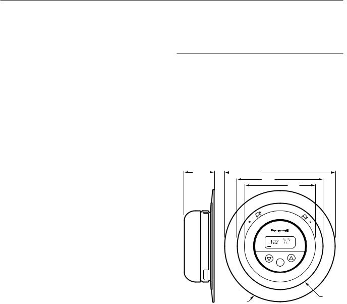
See Fig. 1.
1-1/2 |
|
|
|
5-1/2 |
|
|
4-1/4
3-1/2
|
|
|
T |
|
|
|
|
|
A |
F |
A |
|
|
|
|
E |
|
|
||
|
|
H |
|
|
|
|
|
|
|
|
|
N |
O |
|
|
F |
|
|
|
|
|
|
|
|
|
N |
|
|
|
F |
|
|
|
|
|
|
O |
|
|
|
|
|
|
L |
|
|
|
U |
|
O |
|
|
|
|
A |
|
|
|
|
|
T |
|
C |
O |
|
|
|
|
O |
PM
Set
|
DECORATOR |
T8700 |
M12579 |
COVER PLATE |
THERMOSTAT |
Fig. 1. T8700 Thermostat dimensions (T8700C shown).
ORDERING INFORMATION
When purchasing replacement and modernization products from your TRADELINE® wholesaler or distributor, refer to the TRADELINE® Catalog or price sheets for the complete ordering number.
1.Order number.
2.Accessory, if desired.
If you have additional questions, need further information, or would like to comment on our products or services, please write or phone:
1.Your local Home and Building Control Sales Office (check white pages of your phone directory).
2.Home and Building Control Customer Logistics Honeywell Inc., 1985 Douglas Drive North Minneapolis, Minnesota 55422-4386
In Canada—Honeywell Limited/Honeywell Limitée, 35 Dynamic Drive, Scarborough, Ontario M1V 4Z9.
International Sales and Service Offices in all principal cities of the world. Manufacturing in Australia, Canada, Finland, France, Germany, Japan, Mexico, Netherlands, Spain, Taiwan, United Kingdom, U.S.A.
68-0197—1 |
2 |
T8700B,C AN ELECTRONIC ROUND PROGRAMMABLE THERMOSTAT
INSTALLATION
When Installing this Product…
1.Read these instructions carefully. Failure to follow them could damage the product or cause a hazardous condition.
2.Check the ratings given in the instructions and on the product to make sure the product is suitable for your application.
3.Installer must be a trained, experienced service technician.
4.After installation is complete, check out product operation as provided in these instructions.
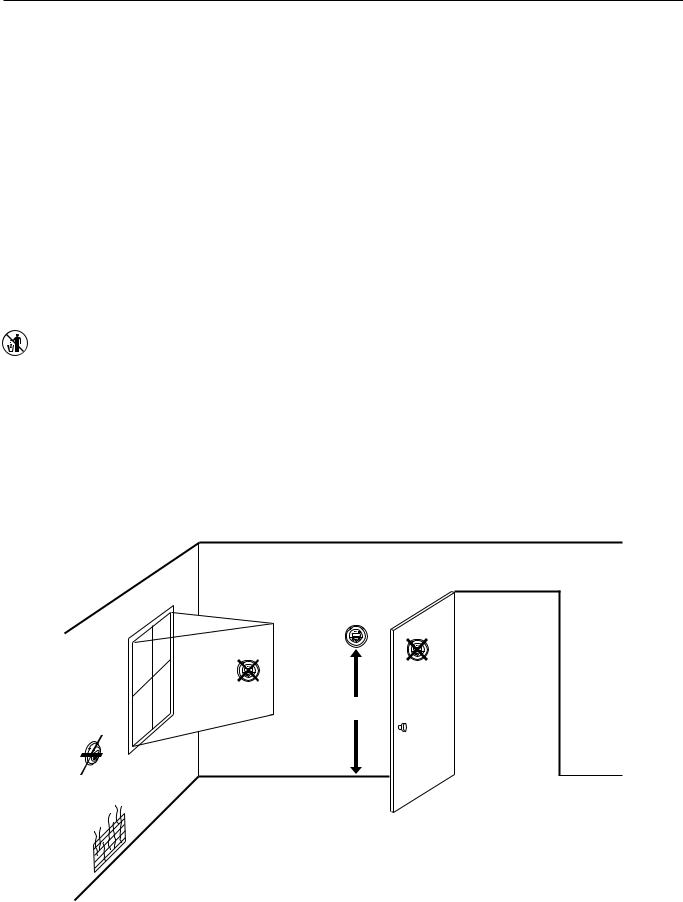
Location
Install the thermostat about 5 ft (1.5m) above the floor in an area with good air circulation at average temperature. See
Fig. 2. Do not install the thermostat where it can be affected by:
—Drafts or dead spots behind doors and in corners.
—Hot or cold air from ducts.
—Radiant heat from the sun or appliances.
—Concealed pipes and chimneys.
—Unheated (uncooled) areas such as an outside wall behind the thermostat.
Mounting Decorator Cover
Plate and Wallplate to Wall
 CAUTION
Damage To Heating/Cooling System Possible.
Be careful when handling wires during installation.
Disconnect power at furnace or at main breaker/fuse box before starting installation.
IMPORTANT
Position and level the wallplate for appearance only. The thermostat functions properly even when not level.
Mount decorator cover plate (if desired), wallplate, T8700 and the screws as follows; see Fig. 3:
RECYCLING NOTICE
If this control is replacing a control that contains mercury in a sealed tube, do not place your old control in the trash.
Contact your local waste management authority for instructions regarding recycling and the proper disposal of an old control containing mercury in a sealed tube.
1.Place the decorator cover plate and the wallplate on the desired wall location.
2.Pull the thermostat wire through the entrance hole on the decorator cover plate, then through the wallplate entrance hole.
3.Plug the wiring hole behind the thermostat to prevent drafts from affecting the thermostat.
4.Select the two mounting holes that best fit the application.
5.Fasten the decorator cover plate and the wallplate to the wall using the provided anchors (if necessary) and screws.
YES
NO
NO
5 FEET
[1.5 METERS]
NO
M12524
Fig. 2. Typical thermostat location.
3 |
68-0197—1 |

T8700B,C AN ELECTRONIC ROUND™ PROGRAMMABLE THERMOSTAT
WALL
DECORATOR
COVER PLATE
PLASTIC SCREW
ANCHOR (2)
WALLPLATE
1
|
|
H |
|
FF |
EA |
|
T |
|
|
O |
|
|
L |
|
|
O |
|
C |
O |
|
|
|
F |
|
|
A |
|
|
N |
|
|
O |
|
|
N |
|
|
A |
|
|
U |
|
|
T |
|
|
O |
1WHEN USING WALL ANCHORS, DRILL 3/16 INCH HOLES FOR DRYWALL, 7/32 INCH HOLES FOR PLASTER OR WOOD.
M12532A
Fig. 3. Mounting decorator cover plate and wallplate on wall (T8700C shown).
ROUTE WIRING AS |
|
|
|
|
ALTERNATE MOUNTING |
|||||
SHOWN THROUGH |
|
|
|
|
|
|
SCREW HOLE |
|||
ENTRANCE |
|
|
T |
F |
|
|
|
|||
|
|
|
|
|
|
|
|
|
||
HOLE |
|
|
|
|
A |
A |
|
|
||
|
|
|
E |
|
|
MOUNTING |
||||
|
|
|
|
H |
|
|
|
|
||
|
|
|
|
|
|
|
|
N |
O |
SCREW |
|
|
|
F |
|
|
|
|
|
N |
HOLE |
|
|
|
F |
|
|
|
|
|
|
|
|
|
|
O |
|
|
|
|
|
|
|
|
|
|
L |
|
|
|
|
|
|
U |
|
|
O |
|
|
|
|
|
|
|
A |
C |
O |
|
|
|
|
|
|
|
T |
|
|
|
|
|
|
|
|
|
O |
||
|
|
|
|
|
|
|
|
|
|
|
R
G
Y
W
|
|
ALTERNATE |
|
|
MOUNTING |
MOUNTING |
|
SCREW HOLE |
WIRING ENTRANCE HOLE |
|
|
SCREW HOLE |
M12529 |
Fig. 4. T8700C wallplate wiring connections. (Refer to Table 1 for T8700B wiring connections.)
The shape of the terminals permits insertion of straight or wraparound wiring connections; either method is acceptable. See Fig. 5.
Wiring
 CAUTION
Damage To Heating/Cooling System Possible. Be careful when handling wires
during installation.
Disconnect power at furnace or at main breaker/fuse box.
IMPORTANT
Use an 18-gauge maximum wire for wiring the T8700 Thermostat.
All wiring must comply with local electrical codes and ordinances. A letter is located near each terminal for identification.
NOTE: To ensure proper mounting of thermostat, restrict all wiring to the left side of the terminals. See Fig. 4.
FOR WRAPAROUND, STRIP 7/16 IN. (11 mm)
FOR STRAIGHT INSERTION,
STRIP 5/16 IN. (8 mm)
M12537
Fig. 5. Wiring connections.
The T8700 Thermostat steals power through the heating and/or cooling system controls and is adaptable to most, 24 Vac systems. Refer to Fig. 6 through 11 for typical wiring hookups.
|
R |
T8700B |
|
|
|
|
|
|
G |
|
|
|
W |
|
|
|
|
FAN |
HEATING |
1 |
|
RELAY |
PRIMARY |
|
|
CONTROL |
|
L1 |
|
|
|
|
|
|
|
(HOT) |
|
24V |
|
L2 |
|
|
|
1 POWER SUPPLY. PROVIDE DISCONNECT MEANS AND
OVERLOAD PROTECTION AS REQUIRED. |
M16005B |
Fig. 6. T8700B1007 Heat Only wiring diagram T8700B1015 Heat Only with Fan includes dotted line.
68-0197—1 |
4 |
 Loading...