


Heating or Cooling Thermostat and Wallplate or Heating/Cooling Thermostat and Subbase
T8090A/191108A, Q682B
OWNER’S MANUAL
1 69-0574—2
69-0574-2

Welcome to the world of energy savings with your new Honeywell fuel saver thermostat. The Honeywell name is your assurance of accurate control and reliable operation for years to come.
Your new thermostat will automatically lower and raise the temperature in your home one or more times every 24 hours. This allows you to significantly lower your fuel costs, while awakening (or returning home) to a comfortable temperature.
Read this manual to learn how to use your new thermostat.
Recycling Notice
M3375
This control contains mercury in a sealed tube. Do not place control in the trash at the end of its useful life.
If this control is replacing a control that contains mercury in a sealed tube, do not place your old control in the trash.
Contact your local waste management authority for instructions regarding recycling and the proper disposal of this control, or of an old control containing mercury in a sealed tube.
If you have questions, call Honeywell Inc. at 1-800-468-1502.
69-0574—2 |
2 |
|
TABLE OF CONTENTS |
Features Of Your Thermostat |
........................................................................................................... 4 |
Setting The Temperature .................................................................................................................. |
7 |
Inserting Clock Batteries ................................................................................................................... |
8 |
Setting The Clock .............................................................................................................................. |
9 |
Programming................................................................................................................................... |
10 |
Troubleshooting .............................................................................................................................. |
14 |
Servicing The Thermostat ............................................................................................................... |
23 |
Cycle Rate Adjustment.................................................................................................................... |
23 |
Thermometer Adjustment ................................................................................................................ |
24 |
Warranty .......................................................................................................................................... |
27 |
3 |
69-0574—2 |
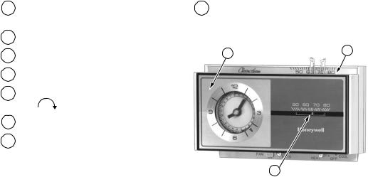
Features Of Your Thermostat
1FLIP-UP COVER. Lift it up to set clock for energy savings and normal temperature
periods.
2THERMOSTAT COVER. Lift up and remove to adjust heat anticipator.
3THERMOMETER. Provides accurate room temperature reading.
4 CLOCK. This clock provides a 24-hour slotted dial to hold the programming pins.
5 CLOCK HANDS. Turn minute hand clockwise to match the correct AM or PM time to the time indicator.
6 TIME INDICATOR. Arrow head indicates time for 24-hour dial.
7PROGRAM INDEX WHEEL. Controls high and low temperature at specific time of day as set by program pins.
8TEMPERATURE SETTING LEVERS. Left (blue mark) controls the low temperature, right (red mark) controls the high temperature.
1 |
2 |
|
3 |
M8726 |
|
69-0574—2 |
4 |
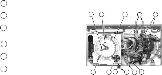
9PROGRAM PINS. Must be inserted into 24-hour clock dial slots to control program index wheel.
10PIN SLOTS. Located on 24-hour dial at 10-minute intervals for program pin insertion.
11MANUAL PROGRAM ADVANCE BUTTON. Allows change from comfort to energy savings setting and vice versa without changing the program.
12HEAT ANTICIPATOR SCALEPLATE. Calibrated to match the heating system current draw in amperes.
13ANTICIPATOR SETTING LEVER. Must be adjusted to match the heating system primary control current.
14MERCURY BULB AND BIMETAL ELEMENT (2). Provide automatic temperature control by switching the heating or cooling system on or off.
5 |
4 |
10 |
8 |
14 |
9 |
7 |
6 |
11 |
12 |
13 |
M8691 |
5 |
69-0574—2 |

15 191108AJ WALLPLATE. Provides mount- |
ing base and wiring connections for |
heating-only or cooling-only thermostat. |
15 |
M2421 |
16Q682B SUBBASE. Provides mounting base, wiring connections and manual switching control for heating/cooling thermostat.
|
|
O |
|
|
|
B |
|
|
R |
|
|
|
|
W |
|
|
G |
|
|
|
|
Y |
|
16 |
|
|
|
FAN |
AUTO |
HEAT |
COOL |
ON |
OFF |
M719
69-0574—2 |
6 |
Setting The Temperature
For Heating:
Set the left lever (blue mark) to the energy savings temperature you want when you are sleeping or your home is unoccupied.
Set the right lever (red mark) to the temperature you want for normal comfort periods.
NOTE: You may override the time program by setting both the red and blue levers to the same temperature set point.
For Cooling:
Set the left lever (blue mark) to the temperature you want for normal comfort periods.
Set the right lever (red mark) to the energy savings temperature you want when you are sleeping or your home is unoccupied.
LOW TEMPERATURE |
HIGH |
|
TEMPERATURE |
||
SETTING LEVER |
||
SETTING |
||
(BLUE MARK) |
||
LEVER |
||
|
||
|
(RED MARK) |
|
|
|
|
|
|
|
50 |
60 |
70 |
80 |
|
|
|
12 |
|
|
|
|
|
||
|
|
|
9 |
8 |
7 |
6 |
|
|
|
|
|
|
|
|
|
|
|
|
|||
|
11 |
10 |
|
|
|
5 |
50 |
60 |
70 |
80 |
|
|
|
|
|
4 |
|||||
|
12 |
|
|
|
|
|
||||
|
|
|
|
|
3 |
|
|
|
|
|
9 |
1 |
|
|
|
|
2 |
3 |
|
|
|
2 |
|
|
|
|
|
|
|
|||
|
|
|
|
1 |
|
|
|
|||
|
|
|
|
|
|
|
|
|
|
|
|
3 |
|
|
|
|
12 |
|
|
|
|
|
4 |
|
|
|
|
|
|
|
|
|
|
|
|
|
|
11 |
|
|
|
|
|
|
|
5 |
|
|
|
|
|
|
|
|
|
|
|
|
|
10 |
|
|
|
|
|
|
|
6 |
7 |
8 |
|
9 |
|
|
|
|
|
|
|
|
6 |
|
|
|
|
|
|
M1520
Fig. 1—Setting high and low temperature levers.
7 |
69-0574—2 |

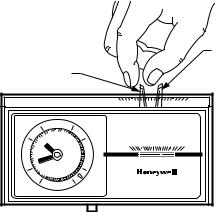
Inserting Clock Batteries
Power is supplied to the clock by the 24 Vac transformer, by two AAA alkaline batteries (included), or by the heating or cooling control circuit. Backup batteries may be installed to supply power to the clock if power is interrupted when using 24 Vac powering method. Install batteries in thermostat as shown in
Fig. 2. Once a year or when batteries are dead, replace with two new AAA alkaline batteries. We recommend Energizer® batteries.
BATTERY LOCATION FOR
(2) AAA BATTERIES; INSTALL WITH POSITIVE ENDS UP
M7188
Fig. 2—Inserting clock batteries.
69-0574—2 |
8 |
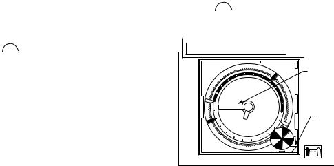
Setting The Clock
Lift thermostat flip-up cover and you’ll find the 24-hour program dial, slotted in 10-minute increments. Adjust the clock to the current time by moving the minute hand carefully in clockwise  direction. DO NOT reverse the minute hand.
When time is correctly set, the Time Indicator Arrow (see Fig. 3) will point to the correct time and corresponding daytime (light) or nighttime (dark) band of the program dial.
EXAMPLE: For 11 PM, the time indicator arrow will point directly to dark band. For 11 AM, the arrow will point to light band on dial.
Daylight Savings Time
When Daylight Savings Time starts, move the minute hand carefully in a clockwise direction one hour. When Daylight Savings
Time ends, move the minute hand carefully in a clockwise  direction 23 hours. Do NOT reverse the minute hand, or damage to timer mechanism may occur.
MINUTE |
HAND |
TIME |
INDICATOR |
ARROW |
M8561 |
Fig. 3—Setting the clock.
9 |
69-0574—2 |
 Loading...