


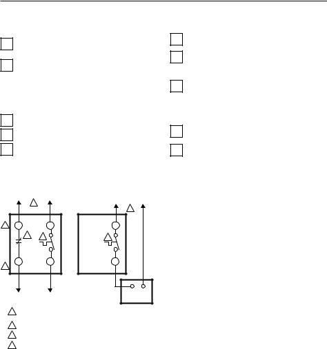
T410A provides single-line break. T410B provides double-line break.
Temperature Range: 40°F to 80°F (4°C to 27°C) Electrical Ratings: 60 Hz noninductive 22A at 120-240 Vac; 19A at 277 Vac
Do-It-Yourself models
Your Honeywell Thermostat
Your new Honeywell T410 Electric Heating Thermostat provides line voltage control of a radiant cable, electric baseboard, and resistive-rated fan forced heaters within the ratings listed above.
 WARNING
This thermostat is a line voltage control (120 Volts to 240 Volts.) Do not install it if you are not completely familiar with house wiring. If handled improperly, there can be risk of a 120 Volt to 240 Volt electric shock hazard, which may cause serious injury or death.
 MERCURY NOTICE
If this control is replacing a control that contains mercury in a sealed tube, do not place you old control in the trash. Dispose of properly.
Contact you local waste management authority for instruction regarding recycling and the proper disposal of a old control.
®U.S. Registered Trademark
Copyright © 2002 Honeywell • |
• All Rights Reserved |
T410A,B
Line Voltage
Electric Heat Thermostats
INSTALLATION INSTRUCTIONS
1PREPARATION
Proper installation of your Honeywell thermostat will occur if you follow these instructions STEP-BY-
STEP. It is recommended that as you read, understand and complete each step, you check it off with pencil or pen.
Check thermostat suitability for your home’s system by reviewing the ratings listed above.
Make certain that your heating system is working, especially if it has been inoperative for a length of
time. If the system does not work, contact your local electrician for assistance.
Carefully unpack your new thermostat. To avoid damage to the sensing element, do NOT remove
the thermostat cover until wiring has been completed.
Save packages of screws, instructions, receipt and proof-of-purchase.
2REMOVE OLD THERMOSTAT
 WARNING
Begin by turning off power to the heating circuit at the main service panel.
Remove cover of old thermostat—cover normally snaps off when pulled firmly from the bottom. If it
resists, check for a screw that locks the cover.
Loosen screws holding thermostat base to outlet box and lift away.
Disconnect wires from old thermostat. As you disconnect each wire, tape the end and label it with
the letter of the terminal designation to make reconnection to new thermostat easier.
Check the old insulation for cracks, nicks or fraying, and apply high quality plastic tape where necessary
for adequate insulation.
Retain the old thermostat for reference purposes and until your new thermostat is functioning
smoothly.
X-XX UL |
69-1562-1 |
T410A,B LINE VOLTAGE ELECTRIC HEAT THERMOSTATS
3WIRE AND MOUNT NEW THERMOSTAT
Remove thermostat cover by grasping the top and bottom ends with fingers, and pulling outward.
Connect wires to the thermostat as shown in the applicable wiring diagram. Push the wires into the
outlet box, and insert the thermostat into the box for mounting by pushing against top and bottom of the thermostat base.
IMPORTANT: Do not press on setting knob.
Secure the thermostat to the box with the two captive mounting screws provided.
Replace thermostat cover.
Set knob to desired room temperature.
IMPORTANT: Rough handling or strong pressure can damage knob or sensing element, and change calibration.
|
|
|
L1 |
|
|
1 |
|
(HOT) |
L2 |
|
|
|
|
|
|
T410B |
|
T410A |
1 |
|
|
|
||
3 |
L2 |
L1 |
L1 |
|
|
2 |
4 |
4 |
|
|
T2 |
T1 |
T1 |
|
3 |
|
|
|
|
|
TO |
|
|
|
|
ELECTRIC |
|
|
|
|
HEATER |
|
|
ELECTRIC |
|
|
|
|
|
|
|
|
|
HEATER |
1POWER SUPPLY. PROVIDE DISCONNECT MEANS AND OVERLOAD PROTECTION AS REQUIRED.
2BREAKS ON POSITIVE OFF.
3EXPOSED UNUSED LEADWIRES TO BE PROPERLY INSULATED.
4THERMALLY ACTIVATED—BREAKS ON TEMPERATURE RISE. MAKES ON TEMPERATURE FALL.
CAUTION:
SPECIAL SERVICE CO/ALR SOLDERLESS CONNECTORS MUST BE USED WHEN CONNECTING WITH ALUMINUM CONDUCTORS;
OTHERWISE, A FIRE HAZARD CAN RESULT.
M19099
4CHECK OUT THERMOSTAT
Turn on the power to the heating system.
Turn setting knob all the way clockwise  ; listen for clicking sound as switch makes contact. Electric
heater should begin operation.
Turn knob all the way counterclockwise  ; listen for clicking sound as switch breaks contact. Electric
heater should shut off.
5SETTING THERMOSTAT
Begin with setting knob at 70°F (20°C) on the scale.
If this setting is not satisfactory after at least two hours of operation, turn setting knob upscale to
raise the temperature, or downscale to lower the temperature. Move knob only a degree each time.
69-1562–1 |
2 |
 Loading...