


ST 3000 Smart Transmitter
Release 300 and SFC Smart Field
Communicator Model STS 103
Installation Guide
34-ST-33-39 2/05

Copyright, Notices, and Trademarks
Printed in U.S.A. – © Copyright 2005 by Honeywell Inc.
February 2005
While this information is presented in good faith and believed to be accurate, Honeywell disclaims the implied warranties of merchantability and fitness for a particular purpose and makes no express warranties except as may be stated in its written agreement with and for its customer.
In no event is Honeywell liable to anyone for any indirect, special or consequential damages. The information and specifications in this document are subject to change without notice.
This document was prepared using Information Mapping® methodologies and formatting principles.
TDC 3000, SFC, Smartline, and ST 3000 are U.S. registered trademarks of Honeywell Inc.
Windows, Windows 95 are trademarks of Microsoft Corporation.
Information Mapping is a trademark of Information Mapping Inc.
Industrial Measurement and Control
Honeywell International Inc.
2500 W. Union Hills Drive
Phoenix, Arizona 85027
ii |
ST 3000 Release 300 Installation Guide |
2/05 |

About This Publication
This manual is intended as a handy guide for installing ST 3000® Release 300 Smart Transmitters. It provides data for checking out, mounting and wiring the transmitter as well as detailed wiring diagrams for reference. Much of this same information is also included in the ST 3000 Smart Transmitter Release 300 and SFC® Smart Field Communicator Model STS 103 User’s Manual 34-ST-25-14 which is the main reference document. We supply this information with each transmitter as an aid in completing installation tasks as quickly as possible.
Procedures in this manual that involve using a Smart Field Communicator (SFC) to “talk” to the transmitter are based on using our latest SFC Model STS103. You can also use the Smartline Configuration Toolkit (SCT 3000) software program to perform transmitter configuration and start up. The SCT 3000 contains an on-line user manual and help information that provides details for setting up the transmitter.
If you will be digitally integrating the ST 3000 transmitter with our TotalPlant® Solution (TPS) system, you will need to supplement this information with data in the PM/APM Smartline® Transmitter Integration Manual which is supplied with the TDC 3000®X bookset. TPS is the evolution of TDC 3000X.
This guide does not apply to Series 100e, non Release 300 Series 100/900 and Series 600 transmitter models. If you have one of these ST 3000 Smart Transmitter Series, refer to the Installation Guide and User’s Manual supplied with the transmitter for information.
Patent Notice
This product is covered by one or more of the following U.S. Patents: 4,520,488; 4,567,466; 4,494,183; 4,502,335; 4,592,002; 4,553,104; 4,541,282; 4,806,905; 4,797,669; 4,735,090; 4,768,382; 4,787,250; 4,888,992; 5,811,690; 5,875,150; 5,765,436; 4,734,873; 6,041,659 and other patents pending.
2/05 |
ST 3000 Release 300 Installation Guide |
iii |
References
Publication |
Publication |
Binder |
Binder |
Title |
Number |
Title |
Number |
|
|
|
|
ST 3000 Smart Transmitter Release 300 |
34-ST-25-14 |
|
|
and SFC Smart Field Communicator |
|
|
|
Model STS 103 User’s Manual |
|
|
|
|
|
|
|
SCT 3000 Smartline Configuration |
34-ST-10-08 |
|
|
Toolkit Start-Up and Installation Manual |
|
|
|
|
|
|
|
Smart Field Communicator Model |
34-ST-11-14 |
|
|
STS103 Operating Guide |
|
|
|
|
|
|
|
For R400 and later: |
|
|
|
PM/APM Smartline Transmitter |
PM12-410 |
Implementation/ |
TDC 2045 |
Integration Manual |
|
PM/APM Optional Devices |
|
|
|
|
|
Symbol Definitions
This CAUTION symbol on the equipment refers the user to the Product Manual for additional information. This symbol appears next to required information in the manual.
This WARNING symbol on the equipment refers the user to the Product Manual for additional information. This symbol appears next to required information in the manual.
WARNING: risk of electrical shock. This symbol warns the user of a potential shock hazard where HAZARDOUS LIVE voltages greater than 30 Vrms, 42.4 Vpeak, or 60 VDC may be accessible.
ATTENTION, Electrostatic Discharge (ESD) hazards. Observe precautions for handling electrostatic sensitive devices
Protective Earth (PE) terminal. Provided for connection of the protective earth (green or green/yellow) supply system conductor.
iv |
ST 3000 Release 300 Installation Guide |
2/05 |

Table of Contents
REFERENCES .................................................................................................................. |
IV |
|
TECHNICAL ASSISTANCE............................................................................................. |
VIII |
|
SECTION 1 —GETTING STARTED ................................................................................... |
1 |
|
1.1 |
CE Conformity (Europe) Notice................................................................................................. |
1 |
1.2 |
Preliminary Checks ................................................................................................................... |
2 |
SECTION 2 —OPTIONAL BENCH CHECK ....................................................................... |
5 |
|
2.1 |
Connecting Power and SCT/SFC ............................................................................................. |
5 |
2.2 |
Testing Communications........................................................................................................... |
7 |
2.3 |
Verifying Configuration Data ................................................................................................... |
10 |
2.4 |
Changing Default Failsafe Direction........................................................................................ |
13 |
2.5 |
Optional Write Protect Jumper ................................................................................................ |
15 |
2.6 |
Setting Range Values Using Local Adjustments..................................................................... |
16 |
SECTION 3 —PREINSTALLATION CONSIDERATIONS................................................ |
17 |
|
3.1 |
Considerations for ST 3000 Transmitter ................................................................................. |
17 |
3.2 |
Considerations for SFC/SCT................................................................................................... |
20 |
3.3 |
Considerations for Local Smart Meter Option......................................................................... |
22 |
SECTION 4 —INSTALLATION......................................................................................... |
23 |
|
4.1 |
Mounting ST 3000 Transmitter................................................................................................ |
23 |
4.2 |
Piping ST 3000 Transmitter..................................................................................................... |
34 |
4.3 |
Wiring ST 3000 Transmitter .................................................................................................... |
39 |
SECTION 5 —REFERENCE DRAWINGS ........................................................................ |
45 |
|
5.1 |
Wiring Diagrams and Dimension Drawings ............................................................................ |
45 |
APPENDIX A SMART METER REFERENCE............................................................... |
51 |
|
A.1 |
Introduction.............................................................................................................................. |
51 |
A.2 |
Smart Meter Display................................................................................................................ |
52 |
A.3 |
Smart Meter Specifications ..................................................................................................... |
53 |
A.4 |
Setting Range Values (Local Zero and Span)......................................................................... |
54 |
A.5 |
Configuring Smart Meter Using Pushbuttons.......................................................................... |
59 |
A.6 |
Configuring Smart Meter Using SFC....................................................................................... |
73 |
A.7 |
Configuring Smart Meter Using SCT 3000.............................................................................. |
79 |
A.8 |
Typical Smart Meter Indications .............................................................................................. |
80 |
APPENDIX B —HAZARDOUS LOCATIONS REFERENCE............................................ |
83 |
|
B.1 |
North American Classification of Hazardous Locations.......................................................... |
83 |
B.2 |
International Electrotechnical Commission (IEC) Classification of Hazardous |
|
Locations ......................................................................................................................................... |
89 |
|
B.3 |
Enclosure Ratings ................................................................................................................... |
93 |
INDEX................................................................................................................................ |
95 |
|
2/05 |
ST 3000 Release 300 Installation Guide |
v |

|
Figures and Tables |
|
Figure 1 |
Typical Power Supply and SCT/SFC Connections to ST 3000. ............................................ |
6 |
Figure 2 |
Location of Failsafe Direction Jumper on PWA. .................................................................. |
14 |
Figure 3 |
Write Protect Jumper Location and Selections.................................................................... |
15 |
Figure 4 |
Typical Mounting Area Considerations Prior to Installation ................................................. |
17 |
Figure 5 |
Typical Bracket Mounted and Flange Mounted Installations ............................................... |
23 |
Figure 6 |
Leveling a Model STA122 or 922 Absolute Pressure Transmitter....................................... |
27 |
Figure 7 |
Typical Flange Mounted Transmitter Installation ................................................................. |
29 |
Figure 8 |
Typical Flush Mounted Transmitter Installation ................................................................... |
30 |
Figure 9 |
Typical Pipe and Flange Mounted Installations ................................................................... |
31 |
Figure 10 |
Typical Remote Diaphragm Seal Transmitter Installation.................................................... |
33 |
Figure 11 |
Typical 3-Valve Manifold and Blow-Down Piping Arrangement. ......................................... |
34 |
Figure 12 |
Typical Arrangement for ½” NPT Process Connection Piping............................................. |
35 |
Figure 13 |
Operating Range for ST 3000 Transmitters......................................................................... |
39 |
Figure 14 |
ST 3000 Transmitter Terminal Block ................................................................................... |
40 |
Figure 15 |
Ground Connection for Lightning Protection........................................................................ |
42 |
Figure A-1 |
Smart Meter Display with All Indicators Lit........................................................................... |
52 |
Figure A-2 |
Typical Setup for Setting Range Values Using Local Zero and Span Adjustments. ........... |
58 |
Table 1 |
Connecting Power Supply and SFC to ST 3000.................................................................... |
6 |
Table 2 |
Testing Communications with Transmitter............................................................................. |
7 |
Table 3 |
Verifying Transmitter’s Configuration Data (Using the SFC) ............................................... |
10 |
Table 4 |
Cutting Failsafe Direction Jumper........................................................................................ |
14 |
Table 5 |
Operating Temperature Limits (Transmitters with Silicone Fill Fluids) ................................ |
18 |
Table 6 |
Transmitter Overpressure Ratings....................................................................................... |
19 |
Table 7 |
Installing and Charging SFC Battery Pack........................................................................... |
20 |
Table 8 |
Mounting ST 3000 Transmitter to a Bracket ........................................................................ |
24 |
Table 9 |
Zero Corrects Procedure for STD110 .................................................................................. |
28 |
Table 10 |
Mounting Remote Diaphragm Seal Transmitter .................................................................. |
32 |
Table 11 |
Suggested Transmitter Location for Given Process ............................................................ |
35 |
Table 12 |
Process Connections ........................................................................................................... |
36 |
Table 13 |
Flange Description ............................................................................................................... |
37 |
Table 14 |
Installing Flange Adapter ..................................................................................................... |
38 |
Table 15 |
Wiring the Transmitter.......................................................................................................... |
41 |
Table A-1 |
Smart Meter PushbuttonDescription .................................................................................... |
52 |
Table A-2 |
Smart Meter Specifications. ................................................................................................. |
53 |
Table A-3 |
Setting Range Values Using Local Zero and Span Adjustments ........................................ |
54 |
Table A-4 |
Smart Meter Engineering Units Code .................................................................................. |
60 |
Table A-5 |
Selecting Engineering Units ................................................................................................. |
61 |
Table A-6 |
Smart Meter Restrictions for Setting Display Values ........................................................... |
63 |
Table A-7 |
Setting Lower Display Values for Smart Meter Display ....................................................... |
64 |
Table A-8 |
Setting Upper Display Value for Smart Meter Display ......................................................... |
68 |
Table A-9 |
Setting Up Smart Meter Configuration Using an SFC ......................................................... |
74 |
Table A-10 |
Summary of Typical Smart Meter Indications. ..................................................................... |
80 |
Table A-11 |
Smart Meter Error Codes and Descriptions......................................................................... |
81 |
Table B-1 |
Factory Mutual (FM) Approval.............................................................................................. |
87 |
Table B-2 |
Canadian Standards Association (CSA) .............................................................................. |
88 |
Table B-3 |
CENELEC / LCIE Certification ............................................................................................. |
91 |
Table B-4 |
Standards Australia (LOSC) Certification ............................................................................ |
92 |
Table B-5 Zone 2 (Europe) Declaration of Conformity ......................................................................... |
92 |
|
Table B-6 |
NEMA Enclosure Type Numbers and Comparable IEC Enclosure Classification............... |
94 |
vi |
ST 3000 Release 300 Installation Guide |
2/05 |

|
Acronyms |
|
|
AP ............................................................................................................................ |
Absolute Pressure |
APM ......................................................................................................... |
Advanced Process Manager |
AWG .................................................................................................................. |
American Wire Gauge |
DE ........................................................................................ |
Digital Enhanced Communications Mode |
DP ......................................................................................................................... |
Differential Pressure |
EMI.......................................................................................................... |
Electromagnetic Interference |
GP............................................................................................................................... |
Gauge Pressure |
HP ................................................................................................................................... |
High Pressure |
HP ............................................................................................... |
High Pressure Side (DP Transmitter) |
inH2O ........................................................................................................................... |
Inches of Water |
KCM ............................................................................................................................ |
Kilo Circular Mils |
LGP................................................................................................................. |
In-Line Gauge Pressure |
LP.................................................................................................................................... |
Low Pressure |
LP................................................................................................ |
Low Pressure Side (DP Transmitter) |
LRV ........................................................................................................................ |
Lower Range Value |
mA..................................................................................................................................... |
Milliamperes |
mmHg ................................................................................................................ |
Millimeters of Mercury |
NPT...................................................................................................................... |
National Pipe Thread |
PCB...................................................................................................................... |
Printed Circuit Board |
PM............................................................................................................................... |
Process Manger |
PROM ............................................................................................ |
Programmable Read Only Memory |
PSI .................................................................................................................. |
Pounds per Square Inch |
PSIA................................................................................................ |
Pounds per Square Inch Absolute |
RFI ......................................................................................................... |
Radio Frequency Interference |
SCT...................................................................................................... |
Smartline Configuration Toolkit |
SFC............................................................................................................. |
Smart Field Communicator |
URL......................................................................................................................... |
Upper Range Limit |
URV ....................................................................................................................... |
Upper Range Value |
Vdc......................................................................................................................... |
Volts Direct Current |
XMTR.................................................................................................................................. |
Transmitter |
2/05 |
ST 3000 Release 300 Installation Guide |
vii |

Technical Assistance
If you encounter a problem with your ST 3000 Smart Transmitter, check to see how your transmitter is currently configured to verify that all selections are consistent with your application.
If the problem persists, you can reach Honeywell’s Solution Support Center for technical support by telephone during normal business hours. An engineer will discuss your problem with you. Please have your complete model number, serial number, and software revision number on hand for reference. You can find the model and serial numbers on the transmitter nameplates. You can also view the software version number using the SFC or SCT 3000 software application.
By Telephone |
Honeywell Solution Support Center Phone: |
|
|
1-800-423-9883 |
(U.S. only) |
|
Outside the U.S. call: 1-602-313-6510 |
|
Additional Help |
|
|
You may also seek additional help by contacting the Honeywell |
||
|
distributor who supplied your ST 3000 transmitter. |
|
By E-mail |
|
|
You can also e-mail your technical questions or comments about this |
||
|
product to: |
|
|
Honeywell Solution Support Center e-mail: ace@honeywell.com |
|
Problem Resolution |
|
|
If it is determined that a hardware problem exists, a replacement |
||
|
transmitter or part will be shipped with instructions for returning the |
|
|
defective unit. Please do not return your transmitter without |
|
authorization from Honeywell’s Solution Support Center or until the replacement has been received.
viii |
ST 3000 Release 300 Installation Guide |
2/05 |
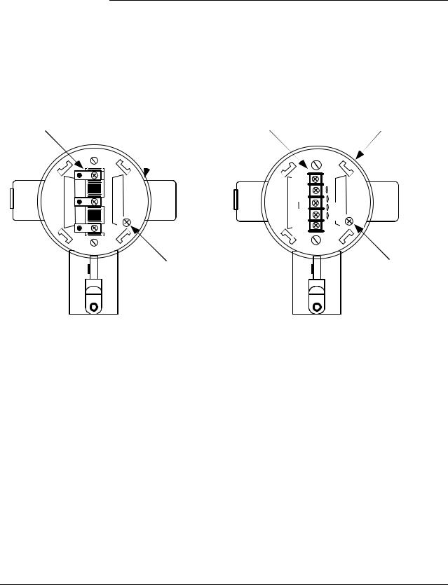
IMPORTANT
Before You Begin, Please Note
Transmitter Terminal
Blocks
Depending on your transmitter options, the transmitter may be equipped with either a 3-screw or 5-screw terminal block inside the electronics housing. This may affect how to connect the loop wiring and meter wiring to the transmitter. See Section 4.3 for the terminal block connections for each type terminal. Section 5 provides additional wiring diagrams showing alternate wiring methods.
Terminal |
Electronics |
Terminal |
Electronics |
|
Housing |
Housing |
|||
Block |
Block |
|||
|
|
SIGNAL+ |
- |
+ - TEST |
SIGNAL |
+ |
+ |
|
- |
SIGNAL |
||
L- |
- |
||
|
+ |
TEST |
|
METER |
+ |
- |
|
- |
|
Internal |
Internal |
Ground |
Ground |
Terminal |
Terminal |
3-Screw Terminal Block |
5-Screw Terminal Block |
|
|
|
|
2/05 |
ST 3000 Release 300 Installation Guide |
ix |

x |
ST 3000 Release 300 Installation Guide |
2/05 |
Section 1 —Getting Started
1.1CE Conformity (Europe) Notice
About conformity and special conditions
This product is in conformity with the protection requirements of 89/336/EEC, the EMC Directive. Conformity of this product with any other “CE Mark” Directive(s) shall not be assumed.
Deviation from the installation conditions specified in this manual, and the following special conditions, may invalidate this product’s conformity with the EMC Directive.
•You must use shielded, twisted-pair cable such as Belden 9318 for all signal/power wiring.
•You must connect the shield to ground at the power supply side of the wiring only and leave it insulated at the transmitter side.
|
|
|
|
|
ATTENTION |
|
|
ATTENTION |
|
|
|
|
The emission limits of EN 50081-2 are designed to provide reasonable |
|
|
|
|
protection against harmful interference when this equipment is operated in an |
|
|
|
|
industrial environment. Operation of this equipment in a residential area may |
|
|
|
|
cause harmful interference. This equipment generates, uses, and can radiate |
|
|
|
|
radio frequency energy and may cause interference to radio and television |
|
|
|
|
reception when the equipment is used closer than 30 meters (98 feet) to the |
|
|
|
|
antenna(e). In special cases, when highly susceptible apparatus is used in |
|
|
|
|
close proximity, the user may have to employ additional mitigating measures |
|
|
|
|
to further reduce the electromagnetic emissions of this equipment. |
|
|
|
|
|
|
2/05 |
ST 3000 Release 300 Installation Guide |
1 |

1.2Preliminary Checks
Checking ST 3000 shipment
Series and model number data
Along with this Installation Guide you should have received
•the ST 3000 Smart Transmitter you ordered, and
•an optional mounting bracket assembly, if applicable.
Before you dispose of the shipping container, be sure you have removed all the contents and visually inspected the transmitter for signs of shipping damage. Report any such damage to the carrier.
Contact us if there is a problem with the order or an item is missing.
Honeywell’s line of ST 3000 Smart Transmitters includes these two major series designations:
•Series 100
•Series 900
Each series includes several models to meet various process pressure measurement and interface requirements. Each transmitter comes with a nameplate located on the top of the electronics housing that lists its given “model number”. The model number format consists of a Key Number with several Table selections as shown below.
|
e |
|
yp |
c |
T |
|
|
si |
|
Ba |
|
Key Number
S 
 T
T 
 D
D 
 1
1 
 2
2 
 0
0
|
|
|
|
|
|
ly |
|
|
|
|
|
|
b |
|
|
|
|
|
|
|
m |
|
|
|
y |
|
|
se |
|
|
|
|
d |
|
|
As |
|
|
s |
r |
Bo |
|
e |
|
|
|
|
|
|
|
|
n |
|||
|
|
|
ng |
|
|
t |
|
ete |
|
la |
|
|
io |
|
|
|
|
|
p |
|
|||
M |
|
F |
|
|
|
O |
|
Table I |
Table II |
|
|
Table III |
|
||


 E
E 
 1
1 
 H
H

 0
0 
 0
0 
 0
0 
 0
0 
 0
0 

 S
S 
 B , 1
B , 1 
 C
C
|
|
|
ion |
|
|
|
at |
|
|
c |
|
|
fi |
|
|
Ide |
nti |
|
|
|
|
|
|
|
y |
r |
|
to |
|
ac |
|
F |
|
Table IV
X X X X
You can quickly identify what series and basic type of transmitter you have from the third and fourth digits in the key number. The letter in the third digit represents one of these basic transmitter types:
A = Absolute Pressure
D = Differential Pressure F = Flange Mounted
G = Gauge Pressure
R = Remote Seals
The number in the fourth digit matches the first digit in the transmitter Series. Thus, a “1” means the transmitter is a Series 100 and a “9” is a Series 900.
Continued on next page
2 |
ST 3000 Release 300 Installation Guide |
2/05 |

1.2 Preliminary Checks, Continued
Series and model number data, continued
ATTENTION
Earlier Release
ST3000 Transmitters
Communicating with the ST3000 Transmitter
For a complete breakdown of the table selections in your model number, please refer to the appropriate Specification and Model Selection Guide that is provided as a separate document.
Previous models of the ST 3000 transmitter with designations of Series 100, Series 100e, Series 600, and Series 900 have been supplied at various times since the ST 3000 was introduced in 1983. While all these transmitters are functionally alike, there are differences in housing and electronics design. This Installation Guide only applies for Release 300, Series 100 transmitters with software version 3.0 or greater and Release 300, Series 900 transmitters with software version b.0 or greater.
Release 300 transmitters can be identified by the “R300” designation on the nameplate.
If you have a Series 100e or a Series 900 non-release 300 transmitter, you must refer to the ST 3000 Smart Transmitter Installation Guide 34-ST-33-31 instead.
Communication with your ST 3000 Smart Transmitter can be accomplished by using any of the following interfaces:
•Honeywell’s hand-held Smart Field Communicator (SFC).
•Smartline Configuration Toolkit (SCT 3000) that runs on a variety of Personal Computer (PC) platforms.
•Global Universal Station (GUS), if the transmitter is digital integrated with Honeywell’s TPS system.
Continued on next page
2/05 |
ST 3000 Release 300 Installation Guide |
3 |

1.2 Preliminary Checks, Continued
Communicating with the ST3000 Transmitter, continued
Using the SFC:
If you ordered an SFC along with your transmitter, locate it and follow the instructions supplied with the SFC Model STS103 to prepare it for operation. Otherwise, be sure you have a fully charged SFC Model STS103 on hand to check the operation of your transmitter.
NOTE: SFC model STS103 with software version 5.0 or greater is fully compatible with all Series 100 and 900, Release 300, ST 3000 transmitters and smart meters. The SFC will operate with transmitters that have older software versions, but functions will be limited to those applicable for the transmitter software.
If your SFC is a Model STS102 instead, you must refer to the ST 3000 Smart Field Communicator for Series 3000 Transmitters Operating Guide 34-ST-11-10 for keystroke details.
Using the SCT:
The SCT 3000 Smartline Configuration Toolkit runs on a variety of PC platforms using MS-DOS 5.0 or higher and Windows 95©, Windows 98 and Windows NT 4.0. It is a bundled Microsoft Windows software and PC-interface hardware solution that allows quick, error-free configuration of Honeywell Smartline field instruments.
NOTE: SCT 3000 software Release 3.12.2 or greater is compatible with all Series 100 and 900, Release 300, ST 3000 transmitters. Please contact your Honeywell representative for more information.
Using reference data |
The ST 3000 Smart Transmitter Release 300 and SFC Smart Field |
|
Communicator Model STS 103 User’s Manual, 34-ST -25-14 was shipped |
|
separately to a person designated on the order. The User’s Manual |
|
contains complete configuration, operation, calibration, service, and |
|
replacement parts information for the transmitter, so you may want to |
|
have it on hand for reference. It also includes the same installation data |
|
contained in this installation guide to minimize cross reference. But, the |
|
optional bench check function and reference dimension drawings list are |
|
included in this guide only. |
|
Appendix A Smart Meter Reference contains configuration and |
|
operating information for using the the ST 3000 when it is equipped with |
|
the smart meter option (option SM). |
|
|
4 |
ST 3000 Release 300 Installation Guide |
2/05 |

Section 2 —Optional Bench Check
2.1Connecting Power and SCT/SFC
About the bench check
The bench check is an optional procedure for checking your transmitter before you install it by:
•Connecting a power source and an SFC (or a PC running SCT 3000 software) to the transmitter
•Running a communication test with an SFC (or SCT 3000)
•Checking the operation status and checking the configuration database
|
Also, if your transmitter was not configured at the factory, you can do so |
|
during this procedure. See the Configuration section in the ST 3000 Smart |
|
Transmitter, Release 300 and SFC Smart Field Communicator Model STS |
|
103 User’s Manual 34-ST-25-14 for details. |
|
When using the SCT 3000, configuration instructions and device |
|
templates are provided on-line to aid in configuring your transmitter. |
Factory Calibration |
|
Each ST 3000 Transmitter is factory calibrated before shipment. |
|
|
• First a full range calibration is performed. |
|
• Next, a turndown calibration is done which is typically between 25% to |
|
50% of its full range. |
|
• Then it is calibrated to a range specified by your purchase order. This |
|
means there is no need to calibrate the transmitter during installation. |
|
(If no range is specified, the transmitter is calibrated to the turndown |
|
factory default.) |
|
• If you need any calibration information, see the appropriate section in |
|
the ST 3000 Smart Transmitter, Release 300 and SFC Smart Field |
|
Communicator Model STS 103 User’s Manual. |
|
• If you have a transmitter with optional local zero and span adjustments, |
|
you may just want to go to Appendix A for the local zero and span |
|
adjustments procedure. |
Procedure |
|
Use the procedure in Table 1 to connect a power supply and an SFC |
|
|
Model STS103 to your transmitter on a bench. See Figure 1 for reference. |
|
|
|
Continued on next page |
2/05 |
ST 3000 Release 300 Installation Guide |
5 |

2.1Connecting Power and SCT/SFC, Continued
|
CAUTION |
|
|
Do not try to remove the transmitter housing end-cap before loosening the |
||||
|
|
|
|
end-cap lock on the transmitter housing. |
||||
|
|
Table 1 |
|
Connecting Power Supply and SFC to ST 3000 |
||||
|
|
|
|
|
|
|
|
|
|
|
|
|
Step |
|
|
Action |
|
|
|
|
|
|
|
|
|
|
|
|
|
1 |
Use a 1.5 mm allen wrench to loosen the end-cap lock on the |
|
|||
|
|
|
|
|
terminal side of the transmitter housing. Unscrew and remove the |
|
||
|
|
|
|
|
end cap from the housing |
|
||
|
|
|
2 |
If the transmitter is supplied with an optional integral analog meter, |
|
|||
|
|
|
|
|
unsnap the meter from the terminal block to expose the wiring |
|
||
|
|
|
|
|
connections. |
|
||
|
|
|
3 |
Observing polarity, connect a 25 Vdc power supply to the |
|
|||
|
|
|
|
|
transmitter’s SIGNAL terminals as shown in Figure 1. |
|
||
|
|
|
|
|
|
|
|
|
|
|
|
|
|
|
ATTENTION |
Be sure there is a minimum of 250 ohms resistance |
|
|
|
|
|
|
between the power supply and the transmitter. |
|
||
|
|
|
|
|
|
|
||
|
|
|
4 |
Connect the SCT or SFC to the transmitter - red lead to SIGNAL |
|
|||
|
|
|
|
|
positive and black lead to SIGNAL negative. See Figure 1. |
|
||
|
|
|
5 |
• If you are using the SCT, Select Tag ID icon from the SCT |
|
|||
|
|
|
|
|
toolbar to establish on-line commnications with the transmitter. |
|
||
|
|
|
|
|
• If you are using the SFC, go to Section 2.2. |
|
||
|
|
|
|
|
|
|
|
|
|
|
|
||||||
Figure 1 |
Typical Power Supply and SCT/SFC Connections to ST 3000. |
|||||||
ST 3000
+ |
+ Red |
25 Vdc
Power
Supply 250Ω
-
 - Black
+ |
SIGNAL |
- |
+ - TEST |
Easy connect terminals for direct SCT or SFC connections
SCT
SFC
6 |
ST 3000 Release 300 Installation Guide |
2/05 |

2.2Testing Communications
Background |
Once you connect power and the SCT or SFC to the transmitter, you are |
||||||||||||||||
|
|
|
|
|
|
|
ready to test communications with the transmitter. |
||||||||||
Procedure |
|
|
|
|
|
|
|
|
|
|
|||||||
|
|
|
|
|
The procedure in Table 2 outlines the steps using an SFC for initiating |
||||||||||||
|
|
|
|
|
|
|
communications with an ST 3000 transmitter without an assigned tag |
||||||||||
|
|
|
|
|
|
|
number. |
|
|
|
|
|
|
|
|||
Table 2 |
|
Testing Communications with Transmitter. |
|
|
|||||||||||||
|
|
|
|
|
|
|
|
|
|
|
|
|
|
||||
Step |
|
Press Key |
|
|
|
|
Read Display or Action |
Description |
|
||||||||
|
|
|
|
|
|
|
|
|
|
|
|
||||||
1 |
|
|
|
|
|
|
Slide power switch on left side of SFC to |
SFC runs its self check and displays |
|
||||||||
|
|
|
|
|
|
|
ON position. |
|
|
|
|
initial prompt. |
|
||||
2 |
|
|
|
|
|
|
|
|
|
|
|
|
|
|
|
If this prompt appears, transmitter is |
|
|
|
|
|
|
|
|
P |
U |
T |
L |
O O P |
I N |
M A N |
|
|
||
|
|
|
|
|
|
|
|
|
|
|
|
|
|
|
|
in Analog mode of operation. This is |
|
|
|
|
|
|
|
|
|
|
|
|
|
|
|
|
|
the factory default mode of |
|
|
|
|
|
|
|
|
|
|
|
|
|
|
|
|
|
operation setting. Put your control |
|
|
|
|
|
|
|
|
|
|
|
|
|
OR |
|
|
loop in the manual mode of |
|
|
|
|
|
|
|
|
|
|
|
|
|
|
|
|
operation before initiating SFC |
|
||
|
|
|
|
|
|
|
|
|
|
|
|
|
|
|
|
|
|
|
|
|
|
|
|
|
|
|
|
|
|
|
|
|
|
communications. Note that you must |
|
|
|
|
|
|
|
|
|
|
|
|
|
|
|
|
|
do this separately through the |
|
|
|
|
|
|
|
|
|
|
|
|
|
|
|
|
|
receiving device in the loop. |
|
|
|
|
|
|
|
|
|
|
|
|
|
|
|
|
|
If this prompt appears, transmitter is |
|
|
|
|
|
|
|
|
|
D E |
– X M T R |
P R E S S I D |
|
|
|||||
|
|
|
|
|
|
|
|
|
in Digital (DE) mode of operation. |
|
|||||||
|
|
|
|
|
|
|
|
|
|
|
|
|
|
|
|
|
|
|
|
|
|
|
|
|
|
|
|
|
|
|
|
|
|
|
|
|
|
|
|
|
|
|
|
|
|
|
|
|
|
|
|
||
3 |
|
|
DE READ |
|
|
|
|
|
|
|
|
|
|
Be sure any switches that may trip |
|
||
|
|
|
|
T |
A |
G |
N O . |
|
|
|
|
||||||
|
|
|
A |
|
|
|
T |
R |
I |
P S |
S E |
C U R |
E D ? ? |
|
alarms or interlocks associated with |
|
|
|
|
|
ID |
|
|
|
|
|
|||||||||
|
|
|
|
|
|
|
|
|
|
|
|
|
|
analog loop are secured or turned |
|
||
|
|
|
|
|
|
|
|
|
|
OR |
|
|
|
||||
|
|
|
|
|
|
|
|
|
|
|
|
|
|
|
|||
|
|
|
|
|
|
|
|
|
|
|
|
|
|
off. Go to Step 4. |
|
||
|
|
|
|
|
|
|
|
|
|
|
|
|
|
|
|||
|
|
|
|
|
|
|
|
|
|
|
|
Go to Step 5 |
|
|
This prompt does not appear for |
|
|
|
|
|
|
|
|
|
|
|
|
|
|
|
|
|
|
transmitters operating in DE mode. |
|
|
|
|
|
|
|
|
|
|
|
|
|
|
|
|
|
See DE transmitter display response |
|
|
|
|
|
|
|
|
|
|
|
|
|
|
|
|
|
in Step 5. |
|
4 |
|
|
NON-VOL |
|
|
Confirms that “TRIPS” are secured. Go |
Required for transmitters operating |
|
|||||||||
|
|
|
ENTER |
|
|
|
to Step 5 for display response. |
in analog mode only. |
|
||||||||
|
|
|
(Yes) |
|
|
|
|
|
|
|
|
|
|
|
|
|
|
|
|
|
|
|
|
|
|
|
|
|
|
|
|
|
|
|
|
|
|
|
|
|
|
|
|
|
|
|
|
|
|
|
|
|
|
|
|
|
|
|
|
|
|
|
|
|
|
|
|
|
|
|
|
|
|
|
|
|
|
|
|
|
|
|
|
|
|
|
|
Continued on next page |
|
2/05 |
ST 3000 Release 300 Installation Guide |
7 |

2.2Testing Communications, Continued
Procedure, continued |
|
|
|
|
|
|
|
|
|
||||
Table 2 |
Testing Communications with Transmitter, Continued |
||||||||||||
|
|
|
|
|
|
|
|
|
|
||||
Step |
Press Key |
|
|
|
|
Read Display or Action |
Description |
|
|||||
|
|
|
|
|
|
|
|
|
|
|
|
|
|
5 |
|
|
|
|
|
|
|
|
|
|
|
Message exchange is taking place |
|
|
|
|
T |
A |
G |
N O . |
|
|
|
|
|
||
|
|
|
|
S |
F |
C |
W O R K |
I |
N |
G . . . |
|
Note that communications with |
|
|
|
|
|
|
|
|
|
|
|
|
|
transmitter are blocked until [ID] key |
|
|
|
|
|
|
|
|
|
|
|
|
|
is pressed |
|
|
|
|
|
|
|
|
|
|
|
|
|
Transmitter is in analog |
|
|
|
|
|
L |
I |
N |
D P |
T |
A |
G N O . |
|
|
|
|
|
|
|
|
|
|
|
_ |
|
|
|
transmission mode. “LIN” means |
|
|
|
|
|
|
|
|
|
|
|
|
|
transmitter is set for linear output |
|
|
|
|
|
|
|
|
OR |
|
|
|
instead of square root (SQRT). “DP” |
|
|
|
|
|
|
|
|
|
|
|
|
means transmitter is differential |
|
||
|
|
|
|
|
|
|
|
|
|
|
|
|
|
|
|
|
|
|
|
|
|
|
|
|
|
pressure type instead of gauge |
|
|
|
|
|
|
|
|
|
|
|
|
|
pressure (GP) or absolute pressure |
|
|
|
|
|
|
|
|
|
|
|
|
|
(AP). Last eight columns in bottom |
|
|
|
|
|
|
|
|
|
|
|
|
|
row are blank when no tag number |
|
|
|
|
|
|
|
|
|
|
|
|
|
has been assigned to this |
|
|
|
|
|
|
|
|
|
|
|
|
|
transmitter. Go to Step 8. |
|
|
|
|
|
D E – X M T R T A G N O . |
|
|
|||||||
|
|
|
|
|
Transmitter is in digital (DE) |
|
|||||||
|
|
|
|
|
|
|
|
_ |
|
|
|
|
|
|
|
|
|
|
|
|
|
|
|
|
|
transmission mode. Last eight |
|
|
|
|
|
|
|
|
|
|
|
|
|
|
|
|
|
|
|
|
|
|
OR |
|
|
|
columns in bottom row are blank |
|
|
|
|
|
|
|
|
|
|
|
|
when no tag number has been |
|
||
|
|
|
|
|
|
|
|
|
|
|
|
|
|
|
|
|
|
|
|
|
|
|
|
|
|
assigned to this transmitter. Go to |
|
|
|
|
|
|
|
|
|
|
|
|
|
Step 7. |
|
|
|
|
|
T |
A |
G |
N O . |
|
|
|
|
|
|
|
|
|
|
|
|
|
|
|
|
||||
|
|
|
|
N O X M T R |
R E S P O N S E |
|
Communication error messages are |
|
|||||
|
|
|
|
|
|
|
|
|
|
|
|
|
|
|
|
|
|
|
|
|
|
|
|
|
|
cycled at two second intervals and |
|
|
|
|
|
|
|
|
|
|
|
|
|
display returns to initial prompt. Go |
|
|
|
|
|
|
|
|
|
|
|
|
|
to Step 6. |
|
6 |
|
|
There is a communication problem, |
Correct any wiring, resistance, or |
|
||||||||
|
|
|
check the |
|
|
|
|
|
power supply problems, and try |
|
|||
|
|
|
• power and SFC connections - Is the |
communicating again - Press [ID] |
|
||||||||
|
|
|
polarity correct; red to positive and |
key. |
|
||||||||
|
|
|
black to negative? |
|
|
|
|
If you are still not getting the |
|
||||
|
|
|
• loop resistance - Is there a minimum |
correct display, note error |
|
||||||||
|
|
|
messages and refer to |
|
|||||||||
|
|
|
of 250 ohms resistance between the |
|
|||||||||
|
|
|
Troubleshooting section in the |
|
|||||||||
|
|
|
SFC and the power supply? |
|
|||||||||
|
|
|
transmitter’s User’s Manual 34-ST- |
|
|||||||||
|
|
|
• power supply - Is power applied, is |
|
|||||||||
|
|
|
25-14 for probable cause. |
|
|||||||||
|
|
|
there greater than 11 volts at the |
|
|||||||||
|
|
|
|
|
|||||||||
|
|
|
transmitter, and are you within the |
|
|
||||||||
|
|
|
operating area on the curve in Figure |
|
|
||||||||
|
|
13? |
|
|
|
|
|
|
|
|
|||
|
|
|
|
|
|
|
|
|
|
|
|
|
|
|
|
|
|
|
|
|
|
|
|
|
|
|
|
|
|
|
|
|
|
|
|
|
|
|
|
Continued on next page |
|
8 |
ST 3000 Release 300 Installation Guide |
2/05 |

2.2Testing Communications, Continued
Procedure, continued |
|
|
|
|
|
|
|
|
|
|
|
|
|
|
|
|
|
|
|||||
Table 2 |
|
|
Testing Communications with Transmitter, Continued |
|
|
||||||||||||||||||
|
|
|
|
|
|
|
|
|
|
|
|
|
|
|
|
||||||||
Step |
Press Key |
|
|
|
|
Read Display or Action |
|
Description |
|
||||||||||||||
|
|
|
|
|
|
|
|
|
|
|
|
|
|
|
|
|
|
|
|
|
|
|
|
7 |
|
|
|
|
|
|
|
|
|
|
|
|
|
|
|
|
|
|
|
Initiates shift key selection. |
|
||
|
|
^ |
|
|
|
D |
E |
– |
X |
M T |
R |
|
T |
A |
G |
N O . |
|
|
|||||
|
|
|
SHIFT |
|
|
|
|
|
|
|
S |
H |
I |
F |
T |
– |
|
|
|
|
|
|
|
|
|
|
|
|
|
|
|
|
|
|
|
|
|
|
|
|
|
|
|
|
|
|
|
|
|
|
|
|
|
|
|
|
|
|
|
|
|
|
|
|
|
|
|
|
|
|
|
|
|
|
DE READ |
|
|
|
|
|
|
|
|
|
|
|
|
|
|
|
|
|
|
||
|
|
|
|
|
T |
A |
G |
|
N O . |
|
|
|
|
|
|
Begins upload of configuration |
|
||||||
|
|
|
A |
|
|
|
S |
F |
C |
|
W O R |
K |
I |
N |
G – |
. 3 3 % |
|
|
|||||
|
|
|
ID |
|
|
|
|
|
database from transmitter. |
|
|||||||||||||
|
|
|
|
|
|
|
|
|
|
|
|
|
|
|
|
|
|
|
|||||
|
|
|
|
|
|
|
|
|
|
|
|
|
|
|
|
|
|
|
|
Operation completion rate is shown |
|
||
|
|
|
|
|
|
|
|
L I N |
|
D P |
|
T A G |
N O . |
|
|
||||||||
|
|
|
|
|
|
|
|
|
|
|
in percent. Note that display for ID |
|
|||||||||||
|
|
|
|
|
|
|
|
|
|
|
|
|
|
|
_ |
|
|
|
|
|
|||
|
|
|
|
|
|
|
|
|
|
|
|
|
|
|
|
|
|
|
|
response reverts to style used for |
|
||
|
|
|
|
|
|
|
|
|
|
|
|
|
|
|
|
|
|
|
|
|
|||
|
|
|
|
|
|
|
|
|
|
|
|
|
|
|
|
|
|
|
|
transmitter in analog mode when |
|
||
|
|
|
|
|
|
|
|
|
|
|
|
|
|
|
|
|
|
|
|
upload is completed. |
|
||
|
|
|
|
|
|
|
|
|
|
|
|
|
|
|
|
|
|
|
|
|
|||
8 |
|
|
F/S DIR |
|
|
|
|
|
|
|
|
|
|
|
|
|
|
|
|
Initiates status check. |
|
||
|
|
|
|
|
S |
T |
A |
T |
U S |
|
|
|
|
|
|
|
|
||||||
|
|
|
U |
|
|
|
S F C |
|
W O R K I N G . . . |
|
|
|
|
|
|||||||||
|
|
|
STAT |
|
|
|
|
|
|
|
|
|
|
||||||||||
|
|
|
|
|
|
|
|
|
|
|
|
|
|
|
|
|
|
|
If messages other than this one are |
|
|||
|
|
|
|
|
|
|
|
|
|
|
|
|
|
|
|
|
|
|
|
|
|||
|
|
|
|
|
|
|
|
S |
T |
A T U S |
|
|
|
|
|
|
|
cycled in display, refer to the |
|
||||
|
|
|
|
|
|
|
|
S T A T U S |
|
C H E C K = O K |
|
|
|||||||||||
|
|
|
|
|
|
|
|
|
|
Troubleshooting section in this |
|
||||||||||||
|
|
|
|
|
|
|
|
|
|
|
|
|
|
|
|
|
|
|
|
|
|||
|
|
|
|
|
|
|
|
|
|
|
|
|
|
|
|
|
|
|
|
manual for an explanation of the |
|
||
|
|
|
|
|
|
|
|
|
|
|
|
|
|
|
|
|
|
|
|
message, the probable cause, and |
|
||
|
|
|
|
|
|
|
|
|
|
|
|
|
|
|
|
|
|
|
|
any corrective action. |
|
||
|
|
|
|
|
|
|
|
L |
I |
N |
|
D |
P |
|
|
|
|
|
|
Signals end of status messages for |
|
||
|
|
|
|
|
|
|
|
|
R |
E |
A |
D Y . . . |
|
|
|
|
display. |
|
|
||||
|
|
|
|
|
|
|
|
|
|
|
|
|
|
|
|
|
|
|
|
|
|
|
|
|
|
|
|
|
|
|
|
|
|
|
|
|
|
|
|
|
|
|
|
|
ATTENTION |
When assigned, |
|
|
|
|
|
|
|
|
|
|
|
|
|
|
|
|
|
|
|
|
|
|
|
|
|
|
|
|
|
|
|
|
|
|
|
|
|
|
|
|
|
|
|
|
|
the transmitter’s tag number also |
|
||
|
|
|
|
|
|
|
|
|
|
|
|
|
|
|
|
|
|
|
|
appears in the top row of the |
|
||
|
|
|
|
|
|
|
|
|
|
|
|
|
|
|
|
|
|
|
|
display. |
|
|
|
|
|
|
|
|
|
|
|
|
|
|
|
|
|
|
|
||||||||
9 |
|
|
|
|
|
|
You have established |
|
|
|
|
|
|
|
|
||||||||
|
|
|
|
|
|
|
|
|
|
ATTENTION |
If you want to |
|
|||||||||||
|
|
|
|
|
|
|
communications with transmitter and |
change the transmitter’s |
|
||||||||||||||
|
|
|
|
|
|
|
are ready to initiate other SFC |
|
|||||||||||||||
|
|
|
|
|
|
|
communication mode from Analog |
|
|||||||||||||||
|
|
|
|
|
|
|
operations. Go to Section 2.3. |
|
|||||||||||||||
|
|
|
|
|
|
|
(A) to digital (DE), see the |
|
|||||||||||||||
|
|
|
|
|
|
|
|
|
|
|
|
|
|
|
|
|
|
|
|
|
|||
|
|
|
|
|
|
|
|
|
|
|
|
|
|
|
|
|
|
|
|
Changing Mode of Operation |
|
||
|
|
|
|
|
|
|
|
|
|
|
|
|
|
|
|
|
|
|
|
section in the transmitter’s User’s |
|
||
|
|
|
|
|
|
|
|
|
|
|
|
|
|
|
|
|
|
|
|
Manual 34-ST-25-14 for details. |
|
||
|
|
|
|
|
|
|
|
|
|
|
|
|
|
|
|
|
|
|
|
|
|
|
|
2/05 |
ST 3000 Release 300 Installation Guide |
9 |

2.3Verifying Configuration Data
Procedure
ATTENTION
Use the procedure in Table 3 to display all the basic transmitter database parameters to be sure they are correct. Note that the values/selections shown in displays are for example purposes only.
•This procedure assumes that you have established communications with the transmitter as outlined in Table 2.
•If any parameter is not set to the correct value/selection or your transmitter was not configured, you can do so now. Refer to the Configuration Section in the ST 3000 Smart Transmitter, Release 300 and SFC Smart Field Communicator Model STS 103 User’s Manual, 34-ST-25-14 for details.
Table 3 |
|
Verifying Transmitter’s Configuration Data (Using the SFC) |
|
|||||||||||||||
|
|
|
|
|
|
|
|
|
|
|
|
|||||||
Step |
Press Key |
|
|
|
|
Read Display or Action |
Description |
|
||||||||||
|
|
|
|
|
|
|
|
|
|
|
|
|
|
|
|
|
|
|
1 |
|
DE READ |
|
|
|
|
|
|
|
|
|
|
|
|
|
This prompt only appears for |
|
|
|
|
|
T |
A |
G |
N O . |
|
|
|
|
|
|
|
|||||
|
|
A |
|
|
|
T |
R |
I |
P S |
S |
E |
C |
U R |
E D ? ? |
|
transmitters in analog mode. |
|
|
|
|
ID |
|
|
|
|
|
|||||||||||
|
|
|
|
|
|
|
|
|
|
|
|
|
|
|
|
This is only required for transmitters |
|
|
|
|
|
|
|
|
|
|
|
|
|
|
|
|
|
|
|
||
|
|
NON-VOL |
|
|
|
|
|
|
|
|
|
|
|
|
|
|||
|
|
|
|
T |
A |
G |
N O . |
|
|
|
|
|
|
|
||||
|
|
ENTER |
|
|
|
S |
F |
C |
W O R |
K |
I |
N |
G . . . |
|
in analog mode. |
|
||
|
|
(Yes) |
|
|
|
|
|
|
|
|
|
|
|
|
|
|
Transmitter’s assigned tag number |
|
|
|
|
|
|
L |
I |
N |
|
D P |
|
T |
A |
G |
N O . |
|
|
||
|
|
|
|
|
|
|
|
|
|
|||||||||
|
|
|
|
|
|
|
||||||||||||
|
|
|
|
|
|
|
|
|
|
|
|
S |
P |
T |
1 Ø Ø 1 |
|
“SPT 1001” appears in bottom row. |
|
|
|
|
|
|
|
|
|
|
|
|
|
|
|
|
|
|
|
|
2 |
|
|
|
|
|
|
|
|
|
|
|
|
|
|
|
|
Present damping time setting. |
|
|
C |
|
|
|
D A |
M |
P |
1 |
|
S |
P |
T |
1 Ø Ø 1 |
|
|
|||
|
|
DAMP |
|
|
|
|
|
|
Ø . |
3 |
|
S |
E |
C |
O N D S |
|
|
|
|
|
|
|
|
|
|
|
|
|
|
|
|
||||||
|
|
|
|
|
|
|
|
|
|
|
|
|
|
|
|
|
|
|
|
|
|
|
|
|
|
|
|
|
|
|
|
|
|
|
|
|
|
|
|
|
|
|
|
|
|
|
|
|
|
|
|
|
|
|
|
|
Continued on next page
10 |
ST 3000 Release 300 Installation Guide |
2/05 |
2.3Verifying Configuration Data, Continued
Procedure, continued |
|
|
|
|
|
|
|
|
|
|
|
|
|
|
|
|
|
|
|
|
|
|||
Table 3 |
|
Verifying Transmitter’s Configuration Data, Continued |
||||||||||||||||||||||
|
|
|
|
|
|
|
|
|
|
|
|
|
|
|
|
|
|
|
|
|
|
|
|
|
Step |
Press Key |
|
|
|
Read Display or Action |
|
|
|
|
|
Description |
|||||||||||||
|
|
|
|
|
|
|
|
|
|
|
|
|
|
|
|
|
|
|
|
|
|
|
||
3 |
|
|
|
|
|
|
|
|
|
|
|
|
|
|
|
|
|
|
|
|
|
Access configuration menu. |
||
|
B |
|
|
|
|
|
S T |
|
C |
O |
N |
F |
I |
G |
|
|
|
|
|
|||||
|
|
CONF |
|
|
C O N |
F O |
R M |
I |
T |
Y ? |
|
|
|
|
|
|
|
|
|
|||||
|
|
|
|
|
|
|
|
|
|
|
|
|
|
|
|
|
|
|
|
|
|
|
|
|
|
|
NON-VOL |
|
|
|
|
|
|
|
|
|
|
|
|
|
|
|
|
|
|
Present output conformity is linear |
|||
|
|
|
C O N |
F O |
R M I |
T |
Y |
|
|
|
|
|
|
|
||||||||||
|
|
|
|
|
|
|
|
|
|
|
|
|||||||||||||
|
|
ENTER |
|
|
|
|
|
|
|
L |
I |
N |
E A |
R |
|
|
|
|
|
|
|
|
|
|
|
|
(Yes) |
|
|
|
|
|
|
|
|
|
|
|
|
|
|
|
|
|
|
|
Exit menu selection. |
||
|
|
|
|
|
|
|
|
|
|
|
|
|
|
|
|
|
|
|
|
|
|
|||
|
|
|
|
|
|
|
|
|
|
|
|
|
|
|
|
|
|
|
|
|
|
|||
|
|
CLR |
|
|
|
|
|
S T |
|
C |
O N |
F |
I |
G |
|
|
|
|
|
|||||
|
|
(No) |
|
|
C O N F O R M I T Y ? |
|
|
|
|
|
|
|
|
|
||||||||||
|
|
|
|
|
|
|
|
|
|
|
|
|
|
|||||||||||
|
|
|
|
|
|
|
|
|
|
|
|
|
|
|
|
|
|
|
|
|
|
Call up next menu selection. |
||
|
|
H |
|
|
|
|
|
S |
T |
|
C |
O |
N |
F |
I |
G |
|
|
|
|
|
|||
|
|
NEXT |
|
|
|
M |
e |
t |
e |
r |
|
C |
o |
n |
f |
i |
g |
? |
|
|
|
|
|
|
|
|
|
|
|
|
|
|
|
|
|
|
|
|
|
|
|
|
|
|
|
|
Enters meter configuration function |
||
|
|
NON-VOL |
|
|
|
|
|
|
|
|
|
|
|
|
|
|
|
|
|
|
|
|||
|
|
|
|
|
M |
e |
t |
e |
r |
|
C |
o |
n |
f |
i |
g |
|
|
|
|
||||
|
|
ENTER |
|
|
S |
F |
C |
|
W |
O |
R |
K |
I |
N |
G |
. |
. |
. |
|
|
|
and confirms that local smart meter |
||
|
|
(Yes) |
|
|
|
|
|
|
|
|
|
|
|
|
|
|
|
|
|
|
|
is present. Timed prompt - See next |
||
|
|
|
|
|
M |
e |
t |
e |
r |
|
C |
o |
n |
f |
i |
g |
|
|
|
|
||||
|
|
|
|
|
|
|
|
|
|
|
display. |
|||||||||||||
|
|
|
|
|
|
|
|
|
|
|
||||||||||||||
|
|
|
|
|
M |
e |
t |
e |
r |
|
B |
d |
|
P |
r |
e |
s |
e |
n |
t |
|
|||
|
|
|
|
|
|
|
|
|
|
|
||||||||||||||
|
|
|
|
|
|
|
|
|
|
|
|
|
|
|
|
|
|
|
|
|
|
|
ATTENTION |
If prompt “No Meter |
|
|
|
|
|
|
|
|
|
|
|
|
|
|
|
|
|
|
|
|
|
|
|
|
|
|
|
|
|
|
|
|
|
|
|
|
|
|
|
|
|
|
|
|
|
|
|
Present” appears, prompt times out |
||
|
|
|
|
|
|
|
|
|
|
|
|
|
|
|
|
|
|
|
|
|
|
in a few seconds, as described |
||
|
|
|
|
|
|
|
|
|
|
|
|
|
|
|
|
|
|
|
|
|
|
above, and calls up the “Configure |
||
|
|
|
|
|
|
|
|
|
|
|
|
|
|
|
|
|
|
|
|
|
|
Meter?” prompt. This means that |
||
|
|
|
|
|
|
|
|
|
|
|
|
|
|
|
|
|
|
|
|
|
|
you can access the meter |
||
|
|
|
|
|
|
|
|
|
|
|
|
|
|
|
|
|
|
|
|
|
|
configuration function without the |
||
|
|
|
|
|
|
|
|
|
|
|
|
|
|
|
|
|
|
|
|
|
|
local smart meter installed. If prompt |
||
|
|
|
|
|
|
|
|
|
|
|
|
|
|
|
|
|
|
|
|
|
|
“Mtr not Supportd” appears, prompt |
||
|
|
|
|
|
|
|
|
|
|
|
|
|
|
|
|
|
|
|
|
|
|
times out and returns to previous ST |
||
|
|
|
|
|
|
|
|
|
|
|
|
|
|
|
|
|
|
|
|
|
|
CONFIG prompt. This means that |
||
|
|
|
|
|
|
|
|
|
|
|
|
|
|
|
|
|
|
|
|
|
|
you are working with a pre-release |
||
|
|
|
|
|
|
|
|
|
|
|
|
|
|
|
|
|
|
|
|
|
|
300 transmitter that does not |
||
|
|
|
|
|
|
|
|
|
|
|
|
|
|
|
|
|
|
|
|
|
|
support the local smart meter option |
||
|
|
|
|
|
|
|
|
|
|
|
|
|
|
|
|
|
|
|
|
|
|
and, therefore, can not access the |
||
|
|
|
|
|
|
|
|
|
|
|
|
|
|
|
|
|
|
|
|
|
|
meter configuration function. |
||
|
|
|
|
|
|
|
|
|
|
|
|
|
|
|
|
|
|
|
|
|
|
Prompt asks if you want to configure |
||
|
|
|
|
|
|
M |
e |
t |
e |
r |
|
C |
o |
n |
f |
i |
g |
|
|
|
|
smart meter. |
||
|
|
|
|
|
C |
o |
n |
f |
i |
g |
u |
r |
e |
|
M |
e |
t |
e |
r |
? |
|
|
|
|
|
|
NON-VOL |
|
|
|
|
|
|
|
|
|
|
|
|
|
|
|
|
|
|
Calls up present meter Engineering |
|||
|
|
|
|
|
|
M |
e |
t |
e |
r |
|
E |
n |
g |
|
U |
n |
i |
t |
s |
|
|||
|
|
ENTER |
|
|
|
|
|
|
Unit selection. |
|||||||||||||||
|
|
|
|
" |
H |
2 |
O |
_ |
3 |
9 |
F |
|
|
|
|
|
|
|
|
|
||||
|
|
(YES) |
|
|
|
|
|
|
|
|
|
|
|
Exit menu selection. |
||||||||||
|
|
|
|
|
|
|
|
|
|
|
|
|
|
|
|
|
|
|
|
|
|
|||
|
|
|
|
|
|
|
|
|
|
|
|
|
|
|
|
|
|
|
|
|
|
|||
|
|
CLR |
|
|
|
|
|
S |
T |
|
C |
O |
N |
F |
I |
G |
|
|
|
|
|
|
|
|
|
|
(No) |
|
|
|
M |
e |
t |
e |
r |
|
C |
o |
n |
f |
i |
g |
? |
|
|
|
|
|
|
|
|
|
|
|
|
|
|
|
|
|
|
|
|
|
|
|
|
|
|
|
|
|
|
|
|
|
|
|
|
|
|
|
|
|
|
|
|
|
|
|
|
|
|
||||||
4 |
|
|
|
|
|
|
|
|
|
|
|
|
|
|
|
|
|
|
|
|
|
SFC will display range values in |
||
|
D |
|
|
U |
N |
I |
T S |
|
1 |
|
S |
P |
T |
|
1 Ø Ø 1 |
|
||||||||
|
|
UNITS |
|
|
|
|
|
|
|
|
|
|
" |
H |
2 |
O _ |
3 9 F |
|
inches of water @ 39º F (4º C). |
|||||
|
|
|
|
|
|
|
|
|
|
|
|
|
|
|
|
|
|
|
|
|
|
|
|
|
|
|
|
|
|
|
|
|
|
|
|
|
|
|
|
|
|
|
|
|
|
|
|
|
|
Continued on next page
2/05 |
ST 3000 Release 300 Installation Guide |
11 |

2.3Verifying Configuration Data, Continued
Procedure, continued
Table 3 |
|
Verifying Transmitter’s Configuration Data, Continued |
||||||||||||||||||
Step |
Press Key |
|
|
|
Read Display or Action |
Description |
||||||||||||||
|
|
|
|
|
|
|
|
|
|
|
|
|
|
|
|
|
|
|
|
|
5 |
|
|
|
|
|
|
|
|
|
|
|
|
|
|
|
|
|
|
|
Present Lower Range Value setting. |
|
E |
|
|
L |
R |
V |
|
1 |
|
|
|
S |
P |
T |
|
1 Ø Ø 1 |
|
|||
|
|
LRV |
|
|
|
Ø |
. Ø Ø Ø Ø |
|
" |
H 2 O _ 3 9 F |
|
|
||||||||
|
|
0% |
|
|
|
|
|
|
|
|||||||||||
|
|
|
|
|
|
|
|
|
|
|
|
|
|
|
|
|
|
|
|
|
|
|
|
|
|
|
|
|
|
|
|
|
|
|
|
|
|
|
|
|
|
6 |
|
|
|
|
|
|
|
|
|
|
|
|
|
|
|
|
|
|
|
Present Upper Range Value setting. |
|
F |
|
|
U R |
V |
|
1 |
|
|
|
S |
P |
T |
|
1 Ø Ø 1 |
|
||||
|
|
URV |
|
|
|
3 |
Ø Ø . |
Ø Ø |
|
" |
H |
2 |
O _ 3 9 F |
|
|
|||||
|
|
100% |
|
|
|
|
|
|
|
|||||||||||
|
|
|
|
|
|
|
|
|
|
|
|
|
|
|
|
|
|
|
||
|
|
|
|
|
|
|
|
|
|
|
|
|
|
|
|
|
|
|
|
|
7 |
|
|
|
|
|
|
|
|
|
|
|
|
|
|
|
|
|
|
|
Initiate shift key selection. |
|
^ |
|
|
|
U R |
V |
|
1 |
|
|
|
S |
P |
T |
|
1 Ø Ø 1 |
|
|||
|
|
SHIFT |
|
|
|
|
|
|
|
S |
H |
I |
F |
T |
– |
|
|
|
|
|
|
|
|
|
|
|
|
|
|
|
|
|
|
|
|
|
|
|
|
|
Access DE configuration menu. |
|
|
DE CONF |
|
|
|
|
|
|
|
|
|
|
|
|
||||||
|
|
|
|
D E |
|
C O N |
F |
|
S |
P T |
|
1 Ø Ø 1 |
|
|||||||
|
|
MENUI |
|
|
|
S |
F |
C |
|
W O R |
K |
I |
N |
G . . . |
|
These parameters apply for |
||||
|
|
ITEM |
|
|
|
|
|
|
|
|
|
|
|
|
|
|
|
|
transmitters in DE mode only. |
|
|
|
|
|
|
|
|
|
|
|
|
|
|
|
|
|
|
|
|
||
|
|
|
|
|
|
|
|
|
|
|
|
|
|
|
|
|
Present output mode setting for |
|||
|
|
|
|
|
|
D E |
|
C O N |
F |
|
S |
P |
T |
|
1 Ø Ø 1 |
|
||||
|
|
|
|
|
|
S |
i |
n |
g |
l |
e |
|
R |
n |
g |
|
w |
/ S V |
|
transmitter in DE mode. |
|
|
|
|
|
|
|
|
|
|
|
|
|
|
|
|
|
|
|
|
|
|
|
H |
|
|
D E |
|
C O N |
F |
|
S |
P |
T |
|
1 Ø Ø 1 |
|
Present broadcast format setting for |
||||
|
|
|
|
|
|
|
|
|
|
|||||||||||
|
|
NEXT |
|
|
|
w |
/ |
D B |
|
( |
6 |
|
B |
y |
t |
e ) |
|
transmitter in DE mode. |
||
|
|
|
|
|
|
|
|
|
|
|
|
|
|
|
|
|
|
|
|
Present failsafe mode setting for |
|
|
|
|
|
|
|
|
|
|
|
|
|
|
|
|
|||||
|
|
H |
|
|
D E |
|
C O N |
F |
|
S |
P |
T |
|
1 Ø Ø 1 |
|
|||||
|
|
NEXT |
|
|
F |
/ |
S |
|
= |
|
B |
/ |
O |
|
H i |
|
|
transmitter in DE mode. |
||
|
|
|
|
|
|
|
|
|
|
|
|
|
|
|
|
|
|
|
|
|
|
|
|
|
|
|
|
|
|
|
|
|
|
|
|
|
|
||||
|
|
CLR |
|
|
L I N |
|
|
D P |
|
S |
P T |
|
1 Ø Ø 1 |
|
Exit DE configuration menu. |
|||||
|
|
|
|
|
R |
E |
A |
D |
Y . . . |
|
|
|
|
|
||||||
|
|
(No) |
|
|
|
|
|
|
|
|
|
|||||||||
|
|
|
|
|
|
|
|
|
|
|
|
|
|
|
|
|
|
|
|
|
|
|
|
|
|
|
|
|
|
|
|
|
|
|
|
|
|
|
|
|
|
8 |
|
|
|
|
|
|
|
|
|
|
|
|
|
|
|
|
|
|
|
Initiate shift key selection. |
|
^ |
|
|
|
L |
I |
N |
|
|
D |
P |
|
S |
P |
T |
|
1 Ø Ø 1 |
|
||
|
|
SHIFT |
|
|
|
|
|
|
|
S |
H |
I |
F |
T |
– |
|
|
|
|
|
|
|
|
|
|
|
|
|
|
|
|
|
|
|
|
|
|
|
|
|
|
|
|
|
|
|
|
|
|
|
|
|
|
|
|
|
|
|
|
|
|
|
|
|
F/S DIR |
|
|
|
|
|
|
|
|
|
|
|
|
|
|
|
Default failsafe direction for analog |
||
|
|
|
F |
/ |
S |
|
D |
I |
R |
|
S |
P |
T |
|
1 Ø Ø 1 |
|
||||
|
|
U |
|
|
F |
/ |
S |
A |
F |
E |
|
U |
P S |
C |
A L E |
|
output. This applies for transmitter in |
|||
|
|
STAT |
|
|
|
|
||||||||||||||
|
|
|
|
|
|
|
|
|
|
|
|
|
|
|
|
|
|
analog mode only. |
||
|
|
|
|
|
|
|
|
|
|
|
|
|
|
|
|
|
|
|
|
|
|
|
|
|
|
|
|
|
|
|
|
|
|
|
|
|
|
|
|
|
|
9 |
|
|
|
|
|
|
|
|
|
|
|
|
|
|
|
|
|
|
|
Initiate shift key selection. |
|
^ |
|
|
|
F |
/ |
S |
|
D |
I |
R |
|
S |
P |
T |
|
1 Ø Ø 1 |
|
||
|
|
SHIFT |
|
|
|
|
|
|
|
S |
H |
I |
F |
T |
– |
|
|
|
|
|
|
|
|
|
|
|
|
|
|
|
|
|
|
|
|
|
|
|
|
||
|
|
|
|
|
|
|
|
|
|
|
|
|
|
|
|
|
|
|
|
|
|
|
URL |
|
|
|
|
|
|
|
|
|
|
|
|
|
|
|
Factory set Upper Range Limit. This |
||
|
|
|
|
U R |
L |
|
1 |
|
|
|
S |
P |
T |
|
1 Ø Ø 1 |
|
||||
|
|
Y |
|
|
|
4 |
Ø Ø . |
Ø Ø |
|
" |
H |
2 |
O _ 3 9 F |
|
can not be changed. |
|||||
|
|
SPAN |
|
|
|
|
|
|||||||||||||
|
|
|
|
|
|
|
|
|
|
|
|
|
|
|
|
|
|
|
||
|
|
|
|
|
|
|
||||||||||||||
|
|
|
|
|
|
|
||||||||||||||
10 |
|
|
|
|
Turn off power and SFC. Remove power |
This completes bench check unless |
||||||||||||||
|
|
|
|
|
leads and SFC leads from transmitter. |
you want to change default failsafe |
||||||||||||||
|
|
|
|
|
Replace integral meter, if applicable; |
direction for analog output and/or |
||||||||||||||
|
|
|
|
|
replace end-cap; and tighten end-cap |
position of optional write protect |
||||||||||||||
|
|
|
|
|
lock |
|
|
|
|
|
|
|
|
|
|
|
|
|
jumper. If you do want to change |
|
|
|
|
|
|
|
|
|
|
|
|
|
|
|
|
|
|
|
|
|
failsafe direction or write protect |
|
|
|
|
|
|
|
|
|
|
|
|
|
|
|
|
|
|
|
|
jumper, go to Section 2.4 or 2.5, |
|
|
|
|
|
|
|
|
|
|
|
|
|
|
|
|
|
|
|
|
respectively. Otherwise, you can |
|
|
|
|
|
|
|
|
|
|
|
|
|
|
|
|
|
|
|
|
now install transmitter. |
|
|
|
|
|
|
|
|
|
|
|
|
|
|
|
|
|
|
|
|
|
12 |
ST 3000 Release 300 Installation Guide |
2/05 |

2.4Changing Default Failsafe Direction
Background
Analog and DE mode differences
ATTENTION
Transmitters are shipped with a default failsafe direction of upscale. This means that the transmitter’s output will be driven upscale (maximum output) when the transmitter detects a critical status.
You can change the direction from upscale to downscale (minimum output) by cutting jumper W1 on the printed wiring assembly (PWA).
If your transmitter is operating in the analog mode, an upscale failsafe action will drive the transmitter’s output to greater than 21 mA or a downscale action will drive its output to less than 3.8 mA.
If your transmitter is operating in the DE mode, an upscale failsafe action will cause the transmitter to generate a “+ infinity” digital signal, or a downscale failsafe action will cause it to generate a “– infinity” digital signal. The STIMV IOP module interprets either signal as “not a number” and initiates its own configured failsafe action for the control system. The STDC card initiates the failsafe mode configured through the transmitter when either signal is generated.
The failsafe direction display that you can access through the SFC only shows the state of the failsafe jumper in the transmitter as it correlates to analog transmitter operation. The failsafe action of the digital control system may be configured to operate differently than indicated by the state of the jumper in the transmitter.
Procedure |
The procedure in Table 4 outlines the steps for cutting the failsafe jumper |
|
on the transmitter’s PWA. Figure 2 shows the location of the failsafe |
|
jumper on the PWA for Release 300 transmitters. |
The nature of the integrated circuitry used in the transmitter’s PWA makes it susceptible to damage by stray static discharges when it is removed from the transmitter. Follow these tips to minimize chances of static electricity damage when handling the PWA.
•Never touch terminals, connectors, component leads, or circuits when handling the PWA.
•When removing or installing the PWA, hold it by its edges or bracket section only. If you must touch the PWA circuits, be sure you are grounded by staying in contact with a grounded surface or wearing a grounded wrist strap.
•As soon as the PWA is removed from the transmitter, put it in an electrically conductive bag or wrap it in aluminum foil to protect it.
Continued on next page
2/05 |
ST 3000 Release 300 Installation Guide |
13 |
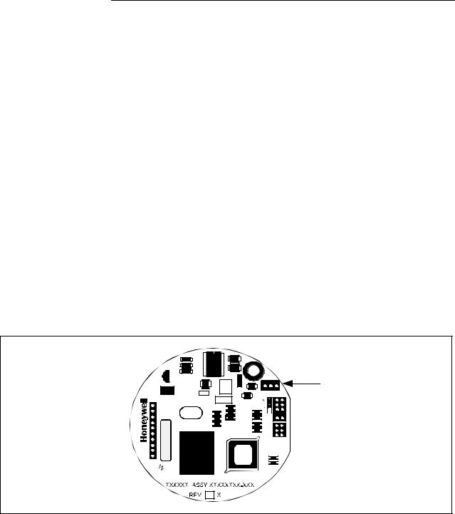
2.4Changing Default Failsafe Direction, Continued
Procedure, continued
Table 4 |
Cutting Failsafe Direction Jumper |
|
|
|
|
|
Step |
Action |
|
|
|
|
1 |
With transmitter on bench and no power applied. Loosen end-cap |
|
|
lock and unscrew end cap from electronics side of transmitter |
|
|
housing. |
|
|
|
|
2 |
• If applicable, unsnap Local Smart Meter from PWA mounting |
|
|
bracket and unplug cable from connector on back of meter |
|
|
assembly. |
|
|
• Loosen two retaining screws and carefully pull mounting bracket |
|
|
and PWA from housing. |
|
|
• Using retaining clip remove flex-tape connector from PWA. |
|
|
• Remove 2-wire power connector from PWA, and then remove |
|
|
PWA and mounting bracket assembly. |
|
|
|
|
3 |
With component side of PWA facing you, locate failsafe jumper W1 |
|
|
and cut it in half with small wire cutter such as dykes. See Figure 2. |
|
|
This changes failsafe action from upscale to downscale. |
|
|
|
|
4 |
Reverse applicable previous steps to replace PWA. |
|
|
|
|
6 |
Turn ON transmitter power. |
|
|
|
Figure 2 Location of Failsafe Direction Jumper on PWA.
Power
Connector


 Meter
Meter
Connector
Failsafe
Direction
Jumper 

|
|
|
|
|
|
|
|
|
|
|
|
|
|
|
14 |
ST 3000 Release 300 Installation Guide |
2/05 |
||
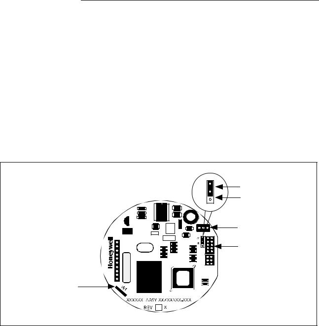
2.5Optional Write Protect Jumper
Write protect option |
The ST 3000 transmitters are available with a “write protect option”. It |
|
consists of a jumper located on the transmitter’s PWA that you can |
|
position to allow read and write access or read only access to the |
|
transmitter’s configuration database. When the jumper is in the read |
|
only position, you can only read/view the transmitter’s configuration |
|
and calibration data. Note that the factory default jumper position is for |
|
read and write access. |
There is no need to check the jumper position unless you want to change it. Refer to the steps in Table 4 to remove the PWA from the transmitter and Figure 3 to reposition the jumper.
Figure 3 shows the location of the write protect jumper on the PWA for
Release 300 transmitters.
Figure 3 Write Protect Jumper Location and Selections.
W |
Read and |
|
R |
Write |
|
Read Only |
||
|
Power |
Connector |
Meter |
Connector |
Failsafe
Direction
Jumper
|
|
|
|
|
|
|
|
|
|
|
|
|
|
|
|
|
|
2/05 |
ST 3000 Release 300 Installation Guide |
15 |
|
||

2.6Setting Range Values Using Local Adjustments
Local zero and span option
About local adjustments
For transmitter applications that do not require an SFC nor digital integration with Honeywell’s TPS systems, ST 3000 transmitters are available with optional local zero and span adjustments.
The transmitter’s range values can be set by using the pushbuttons on the face of the local zero and span option or smart meter. Refer to the procedure for setting the range values to applied pressures using local zero and span adjustments in Appendix A Smart Meter Reference in this guide.
16 |
ST 3000 Release 300 Installation Guide |
2/05 |
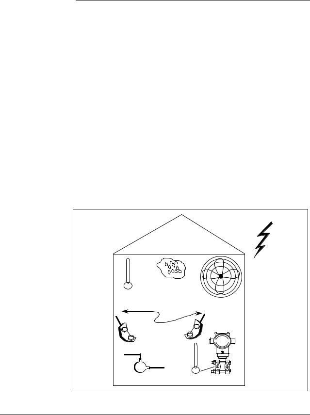
Section 3 —Preinstallation Considerations
3.1Considerations for ST 3000 Transmitter
Evaluate conditions The ST 3000 transmitter is designed to operate in common indoor industrial environments as well as outdoors. To assure optimum performance, evaluate these conditions at the mounting area relative to published transmitter specifications and accepted installation practices for electronic pressure transmitters.
•Environmental Conditions
–Ambient Temperature
–Relative Humidity
•Potential Noise Sources
–Radio Frequency Interference (RFI)
–Electromagnetic Interference (EMI)
•Vibration Sources
–Pumps
–Motorized Valves
–Valve Cavitation
•Process Characteristics
–Temperature
–Maximum Pressure Rating
Figure 4 illustrates typical mounting area considerations to make before installing a transmitter.
Figure 4 Typical Mounting Area Considerations Prior to Installation
|
|
Lightning |
|
|
(EMI) |
Relative |
|
|
Humidity |
|
|
Ambient |
|
|
Temperature |
Large Fan Motors |
|
|
|
|
|
(EMI) |
|
Transceivers |
|
|
(RFI) |
|
|
Pump |
Meter Body |
|
(vibration) |
Temperature |
21003 |
Continued on next page
2/05 |
ST 3000 Release 300 Installation Guide |
17 |

3.1Considerations for ST 3000 Transmitter, Continued
Temperature limits |
Table 5 lists the operating temperature limits for the various types of |
||||||
|
|
transmitters with silicone fill fluids. See transmitter specifications for |
|||||
|
|
temperature limits of transmitter with alternative fill fluids. |
|
||||
Table 5 |
Operating Temperature Limits (Transmitters with Silicone Fill Fluids) |
|
|||||
|
|
|
|
|
|||
Transmitter Type and Model |
Ambient Temperature |
Process Interface Temperature |
|||||
|
|
|
°C |
°F |
°C |
|
°F |
Draft Range |
STD110 |
-40 to 70 |
-40 to 158 |
-40 to 70 |
|
-40 to 158 |
|
Differential PressureSTD125 |
-40 to 85 |
-40 to 185 |
-40 to 85 |
|
-40 to 185 |
||
STD120, STD130, STD170 |
-40 to 93 |
-40 to 200 |
-40 to 125 |
|
-40 to 257 |
||
|
STD904, STD924, |
|
|
|
|
|
|
|
STD930, STD974 |
-40 to 85 |
-40 to 185 |
-40 to 125 |
|
-40 to 257 |
|
Gauge Pressure |
|
|
|
|
|
|
|
STG140, STG170, STG180, |
|
|
|
|
|
||
STG14L, STG17L, STG18L |
-40 to 93 |
-40 to 200 |
-40 to 125 |
|
-40 to 257 |
||
|
|
STG14T |
-40 to 93 |
-40 to 200 |
-40 to 150 † |
|
-40 to 302 † |
|
|
STG93P |
-15 to 65 |
5 to 149 |
-15 to 95 †† |
|
5 to 203 †† |
|
STG944, STG974 |
-40 to 85 |
-40 to 185 |
-40 to 125 |
|
-40 to 257 |
|
|
STG90L, STG94L, |
|
|
|
|
|
|
|
STG97L, STG98L |
-40 to 85 |
-40 to 185 |
-40 to 110 |
|
-40 to 230 |
|
Absolute Pressure |
STA122 |
-40 to 93 |
-40 to 200 |
See Specification Sheet |
|||
|
|
STA140 |
-40 to 93 |
-40 to 200 |
-40 to 80 |
|
-40 to 176 |
|
|
STA922 |
-40 to 85 |
-40 to 185 |
See Specification Sheet |
||
|
|
STA940 |
-40 to 85 |
-40 to 185 |
-40 to 80 |
|
-40 to 176 |
Flange Mounted |
|
|
|
|
|
|
|
STF128, STF132, STF924, |
-40 to 93 |
-40 to 200 |
-40 to 175 |
|
-40 to 350 |
||
STF932 |
|
|
|
||||
Pseudo-Flanged Head |
|
|
|
|
|
||
STF12F, STF13F, STF92F, |
-40 to 93 |
-40 to 200 |
-40 to 93 |
|
-40 to 200 |
||
STF93F |
|
|
|
||||
STF14F |
|
|
-40 to 85 |
-40 to 185 |
-40 to 85 |
|
-40 to 185 |
Gauge Pressure Flange Mount |
-40 to 93 |
-40 to 200 |
-40 to 150 † |
|
-40 to 302 † |
||
STF14T |
|
|
|
||||
Remote Diaphragm Seals |
|
|
|
|
|
||
STR12D, STR13D, STR14G, |
|
|
|
|
|
||
|
STR17G, STR14A |
See Specification Sheet |
See Specification Sheet |
||||
|
STR93D, STR94G |
-40 to 85 |
-40 to 185 |
See Specification Sheet |
|||
†Process temperatures above 125 °C (257 °F) require a reduction in the maximum ambient temperature as follows:
Process Temperature |
Ambient Temperature Limit |
150 °C (302 °F) |
50 °C (122 °F) |
140 °C (284 °F) |
60 °C (140 °F) |
125 °C (257 °F) |
85 °C (185 °F) |
†† Process temperatures above 65 °C (149 °F) require a 1:1 reduction in maximum ambient temperature. NOTE: For transmitters with local meter option see Table A-2.
NOTE: Transmitters with other fill fluids (CTFE, Neobee, Etc.) have different Operating Temperature Limits. For more specific information, refer to the appropriate Specification and Model Selection Guide or transmitter nameplate
18 |
ST 3000 Release 300 Installation Guide |
2/05 |

3.1Considerations for ST 3000 Transmitter, Continued
Pressure ratings |
Table 6 lists maximum working pressure for a given transmitter Upper |
|
Range Limit (URL). |
|
The maximum allowable working pressure (MAWP) is the pressure |
|
used for the approval body safety calculations. |
Table 6 Transmitter Maximum Allowable Working Pressure (MAWP) Ratings
Transmitter Type |
Upper Range Limit |
MAWP |
|
(URL) |
|
|
|
|
Draft Range |
10 inches H2O (25 |
50 psi (3.5 bar) |
|
mbar) |
|
|
|
|
Differential Pressure |
400 inches H2O (1 bar) |
3000 psi (210 bar) |
|
100 psi (7 bar) |
3000 psi (210 bar) |
|
|
|
|
3000 psi (210 bar) |
3000 psi (210 bar) |
|
|
|
Gauge Pressure |
100 psi (7 bar) |
100 psi (7 bar) |
|
|
|
|
300 psi (21 bar) |
300 psi (21 bar) |
|
|
|
|
500 psi (35 bar) |
500 psi (35 bar) |
|
|
|
|
3000 psi (210 bar) |
3000 psi (210 bar) |
|
|
|
|
6000 psi (415 bar) |
6000 psi (415 bar) |
|
|
|
|
10000 psi (690 bar) |
10000 psi (690 bar) |
|
|
|
Flange Mount |
400 inches H2O (1 bar) |
Per selected flange and material |
|
|
(ANSI/ASME 150#, 300#, DN |
|
100 psi (7 bar) |
|
|
PN40) |
|
|
|
|
Remote Seal |
400 inches H2O (1 bar) |
Lesser MAWP of either Remote |
|
|
Seal selected or transmitter |
|
100 psi (7 bar) |
|
|
pressure rating |
|
|
|
|
Absolute Pressure |
780 mmHg Absolute |
780 mmHg Absolute |
|
(1 bar) |
(1 bar) |
|
|
|
|
500 psia (35 bar) |
500 psia (35 bar) |
|
|
|
Note: Maximum Allowable Working Pressure (MAWP) may vary with materials of construction and process temperature. For more specific information, refer to the appropriate Specification and Model Selection Guide or transmitter nameplate
Note: To convert bar values to kilopascals (kPa), multiply by 100. For example, 3.5 bar equals 350 kPa.
2/05 |
ST 3000 Release 300 Installation Guide |
19 |
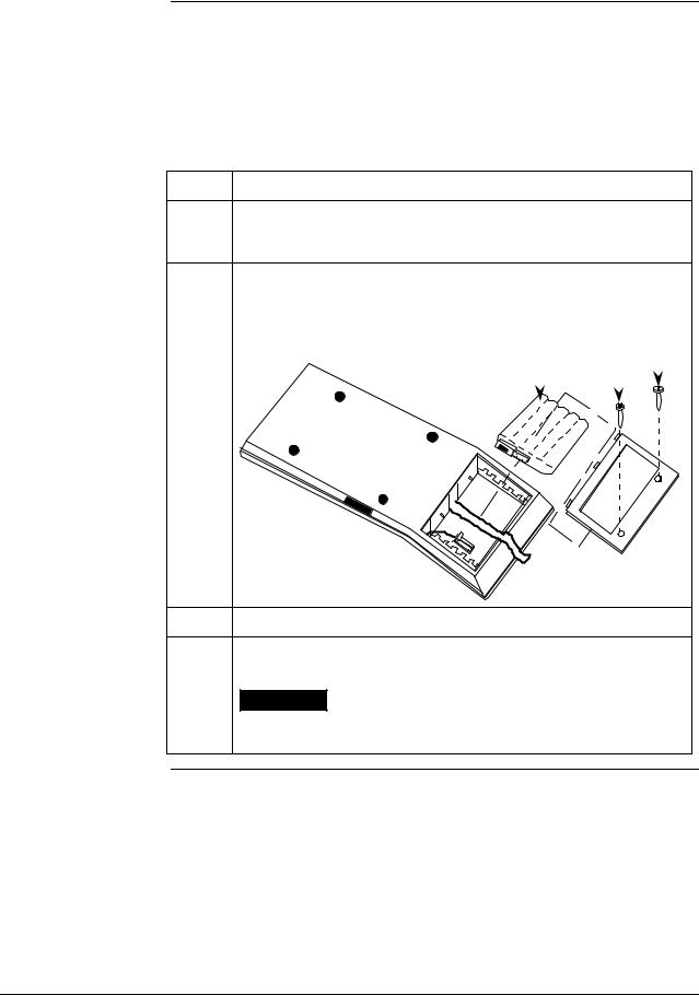
3.2Considerations for SFC/SCT
Install SFC battery pack
If the SFC battery pack was removed for shipping and/or storage, you will have to install the battery pack and charge the batteries before you can operate the SFC.
The procedure in Table 7 outlines the steps for the battery pack.
Table 7 Installing and Charging SFC Battery Pack
Step |
Action |
1Turn SFC face down on working surface. Use metric hex wrench (2.5 mm) to remove screws in battery compartment cover and remove cover.
2Insert battery pack in compartment and connect plug in compartment to pin on battery back
Example - Battery pack installation.
Battery Pack |
|
Hex Screws |
|
|
|
|
|
||||
|
|||||
|
|
|
|
|
|
|
|
|
|
|
|
|
|
|
|
|
|
|
|
|
|
|
|
21004
3Replace cover and tighten hex screws
4Connect lead from battery charger to recessed connector on left side of SFC.
WARNING The SFC battery charger is not intrinsically safe. Always recharge the SFC battery pack in a nonhazardous location. The SFC itself is an intrinsically safe device.
Continued on next page
20 |
ST 3000 Release 300 Installation Guide |
2/05 |
 Loading...