


S9361A
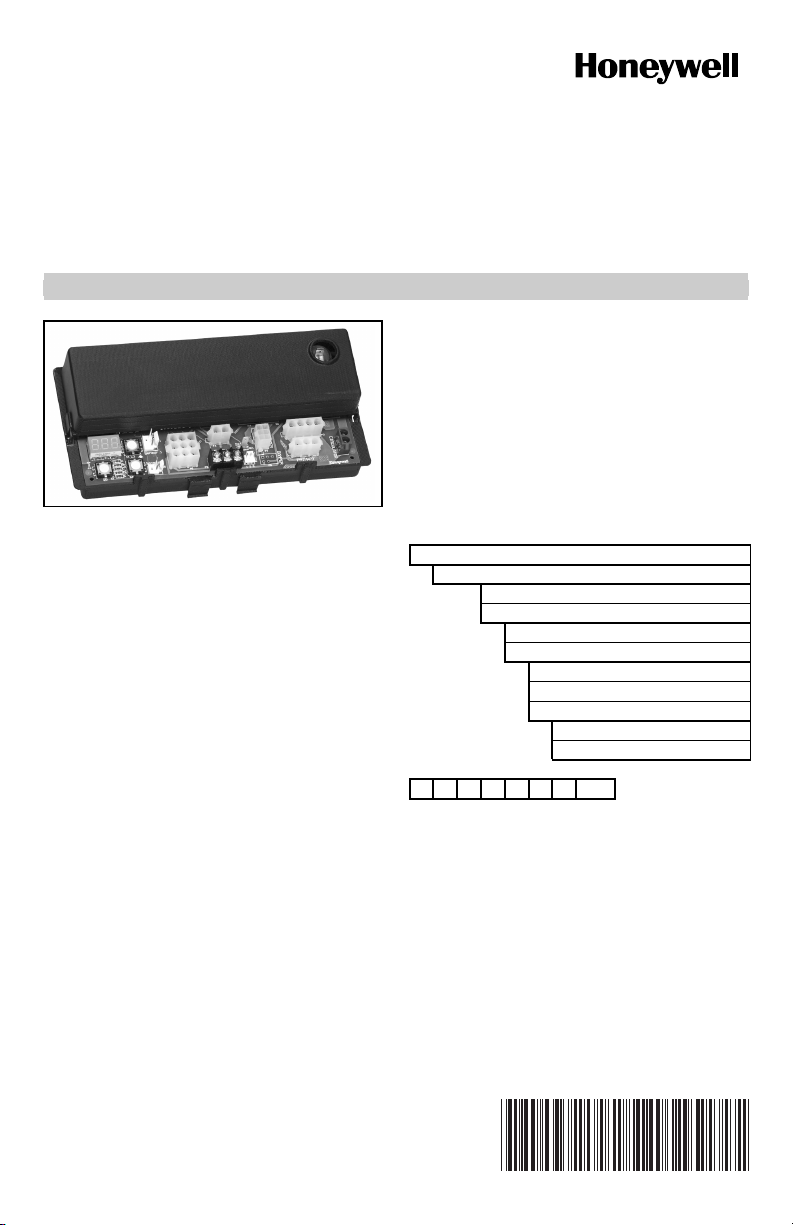
S9360A, S9361A, S9370A, S9371A
Integrated Boiler Controllers
INSTALLATION INSTRUCTIONS
SPECIFICATIONS
IMPORTANT:
The specifications given in this publication do
not include normal manufacturing tolerances.
Therefore, an individual unit may not match the
listed specifications exactly. Also, this product is
tested and calibrated under closely controlled
conditions, and some minor differences in
performance can be expected if those
conditions are changed.
Model Numbers
APPLICATION
These integrated boiler control modules provide ignition
sequence, flame monitoring and safety shutoff for either
intermittent pilot spark ignition or direct hot surface
ignition heating systems. They also provide limit rated
water temperature control and display interface capability
for either “on-board” or remote user interface
applications.
• S9360A—Spark Ignition, Intermittent Pilot, Remote
Display.
• S9361A—Spark Ignition, Intermittent Pilot, “On board”
Display.
• S9370A—Hot Surface Ignition, Remote Display.
• S9371A—Hot Surface Ignition, “On board” Display.
• Enabled with EnviraCOM™ communication capability
to support remote monitoring and diagnostics.
• Limit-rated Temperature Sensing Probe.
• One or Two Sensor Models.
S—Switching Control
93—Integrated Hydronic Control Platform
6—Spark Ignition
7—Hot Surface Ignition
0—Remote Display Required
1—Integrated On-Board Display
A—Boiler Control
B—Water Heater Control
C—Pool Heater Control
1—No Circulator
2—On/Off Circulator
S9360A1000
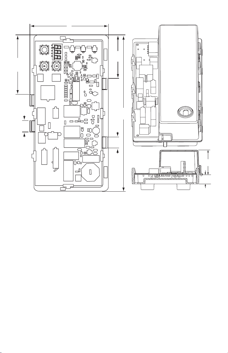
Dimensions:
See Fig. 1.
69-2076-01
S9360A, S9361A, S9370A, S9371A INTEGRATED BOILER CONTROLLERS
111
I
2 x 84.5
2 x 15
Fig. 1. S936X Integrated Boiler Controller, dimensions in in. (mm).
Electrical Ratings:
Line Voltage: 120 Vac, 60 Hz (220 Vac, 50 Hz on specific
model numbers).
Transformer:
Nominal 24 Vac (maximum 30 Vac, minimum 18 Vac).
5.0 VA plus external loads (gas valve, vent damper, etc.)
On/Off Circulator:
Full Load: 7.4A at 120 Vac (0.75 to 0.8 power factor
[PF]). (220 Vac TBD.)
Locked Rotor: 44.4A at 120 Vac (0.4 to 0.5 PF). (220
Vac TBD.)
Inducer (Optional):
Full Load: 6A at 120 Vac (0.75 to 0.8 PF). (220 Vac
TBD.)
Locked Rotor: 17.48A at 120 Vac (0.4 to 0.5 PF). (220
Vac TBD.)
Vent Damper (Optional):
Full Load: 0.5A at 24 Vac.
In Rush: 1A at 24 Vac.
Main Valve:
Full Load: 2A at 24 Vac (0.5 to 0.6 PF).
In Rush: 6A at 24 Vac (0.5 to 0.6 PF)
Pilot Valve (Optional):
Full Load: 2A at 24 Vac (0.5 to 0.6 PF)
In Rush: 6A at 24 Vac (0.5 to 0.6 PF).
Hot Surface Igniter (HSI) (Optional):
2 x 61
220.5
2 x 15
1-3/8
(35)
5/8
(16)
M24217
Full Load: 4.5A at 120 Vac.
Warm-up Time:
18 seconds for first trial for ignition; this varies by
model, as does the time for the second trial for ignition (recommended for Norton igniter model 201 or
270 or equivalent)
Ambient Ratings:
Humidity: 0 to 95 percent relative humidity,
noncondensing.
Operating Ambient Temperature: -30°F to +150°F.
Shipping Ambient Temperature: -40°F to +175°F.
Flame Monitoring (May vary by model):
Flame Establishing Period (FEP): Maximum 2 seconds.
Flame Failure Response Time (FFRT):
Maximum: 2 seconds @ 1 µA.
Flame Stabilization Time: 4 seconds. Time from ignit-
ing the main burner and detecting loss of flame (the
flame current is allowed to be under the flame lost
threshold for this time while waiting for burner to
stabilize).
Flame Lost Threshold: 0.23 µA.
Ignition Cables:
Use cable types recommended in Table 1.
69-2076—01 2

S9360A, S9361A, S9370A, S9371A INTEGRATED BOILER CONTROLLERS
Table 1. Recommended Ignition Cables.
Cable Type
UL Style
3217
UL Style
3257
Transformer Requirement:
Add current ratings of module, pilot valve, main valve,
vent damper and any other components of the control
system to determine transformer size requirement.
Approvals:
Varies with control model.
ANSI Z21.20 Automatic Gas Ignition Systems and
Components.
ANSI Z21.23 Gas Appliance Thermostats.
EN298: Automatic Gas Burner Control Systems
ANSI Z21.87: Automatic Gas Shutoff Devices for Hot
Water Supply Systems.
UL353 Limit Controls.
Vol tag e
Rating (rms)
10,000 150 302
10,000 250 484
Temperature Rating
°C °F
PLANNING THE INSTALLATION
Automatic Ignition Control domestic and commercial
boiler systems are used on a wide variety of equipment.
Some of these applications may make heavy demands on
the controls, either because of frequent cycling, or
because of moisture, corrosive chemicals, dust or
excessive heat in the environment. In these situations,
special steps may be required to prevent nuisance
shutdowns and premature control failures. These
applications require Honeywell Engineering review;
contact your Honeywell Sales Representative for
assistance.
Frequent Cycling
These controls are designed for use on domestic and
commercial boiler systems that typically cycle less than
10,000 cycles per year. In an application with significantly
greater cycling rates, we recommend monthly checkout
because the controls may wear out more quickly.
High Humidity or Dripping Water
Over time, dripping water or high ambient humidity can
create unwanted electrical paths on the module circuit
board, causing the module to fail. Never install an
appliance where water can drip on the controls.
In addition, high ambient humidity can cause the control
to corrode and finally fail.
Where the appliance may be installed in a humid
atmosphere, make sure air circulation around the module
and gas control is adequate to prevent condensation. It is
also important to regularly check out the system. A NEMA
4 enclosure may be needed.
Corrosive Chemicals
Corrosive chemicals can also attack the module and gas
control and eventually cause a failure. Where chemicals
may be used routinely for cleaning, make sure the
cleaning solution cannot reach the controls. Where
chemicals are likely to be suspended in the air, as in some
industrial and agricultural applications, protect the module
from exposure with a NEMA 4 enclosure.
Dust or Grease Accumulation
Heavy accumulation of dust or grease may cause the
controls to malfunction. Where dust or grease may be a
problem, provide covers for the module and gas control
that limit environmental contamination. A NEMA 4
enclosure is recommended for the module.
Heat
The controls can be damaged by excessively high
temperatures. Make sure the maximum ambient
temperature at the control locations will not exceed the
rating of the control. If the appliance normally operates at
very high temperatures, insulation, shielding, and air
circulation may be necessary to protect the controls.
Proper insulation or shielding should b provided by the
appliance manufacturer; make sure adequate air
circulation is maintained when the appliance is installed.
INSTALLATION AND CHECKOUT
Water or Steam Cleaning
Once a module or gas control has been wet, it may
operate unreliably and must be replaced. If the appliance
is likely to be cleaned with water or steam, the controls
and associated wiring should be covered so that water or
steam cannot reach them. The controls should be high
enough above the bottom of the cabinet so they will not
be subjected to flooding or splashing during normal
cleaning procedures. If necessary, shield the controls to
protect them from splashing water. A NEMA 4 enclosure
is recommended.
When Installing This Product…
1. Read these instructions carefully. Failure to follow
them could damage the product or cause a
hazardous condition.
2. Check the ratings given in the instructions and on
the product to make sure they are suitable for your
application.
3. Installer must be a trained, experienced service
technician.
4. After installation is complete, check out product
operation as provided in these instructions.
3 69-2076—01
S9360A, S9361A, S9370A, S9371A INTEGRATED BOILER CONTROLLERS
WARNING
Fire or Explosion Hazard.
Can cause severe injury, death or property
damage.
1. The module can malfunction if it gets wet,
leading to accumulation of explosive gas.
• Never install where water can flood, drip or
condense on module.
• Never try to use a module that has been
wet—replace it.
2. Liquefied petroleum (LP) gas is heavier than air
and will not vent upward naturally.
• Do not light pilot or operate electric switches,
lights, or appliances until you are sure the
appliance area is free of gas.
3. If a new gas control is to be installed, turn off
gas supply before starting installation. Conduct
Gas Leak Test according to gas control
manufacturer instructions after the gas control
is installed.
4. If module must be mounted near moisture or
water, provide suitable waterproof enclosure.
WARNING
Electrical Shock Hazard.
Can cause severe injury, death or property
damage.
Disconnect power supply before beginning wiring
to prevent electrical shock or equipment damage.
Perform Preinstallation Safety Inspection
The preinstallation checks described in ANSI Standard
Z21.71 must be done before a replacement module is
installed. If a condition which could result in unsafe
operation is detected, the appliance should be shut off
and the owner advised of the unsafe condition. Any
potentially unsafe condition must be corrected before
proceeding with the installation.
Maintenance Requirements in Severe
Environments
Regular preventive maintenance is important in any
application, but especially so in commercial, agricultural,
and industrial applications, because:
1. In such applications, particularly commercial, the
equipment can operate 100,000 to 200,000 cycles
per year. Such heavy cycling can wear out the gas
control in one to two years. A normal boiler application, for which the controls were intended, typically
operate fewer than 10,000 cycles per year.
2. Exposure to water, dirt, chemicals, and heat can
damage the module or the gas control and shut
down the control system. A NEMA 4 enclosure can
reduce exposure to environmental contaminants.
The maintenance program should include regular
checkout of the system as outlined under Checkout.
WARNING
Fire or Explosion Hazard.
Can cause severe injury, death or property
damage.
Do not attempt to take the module apart or to
clean it. Improper reassembly and cleaning may
cause unreliable operation, leading to an
accumulation of explosive gas.
Maintenance frequency must be determined individually
for each application. Some considerations are:
Cycling frequency. Appliances that may cycle more than
10,000 times annually should be checked monthly.
Intermittent use. Appliances that are used seasonally
should be checked before shutdown and again before the
next use.
Consequence of unexpected shutdown. Where the cost of
an unexpected shutdown would be high, the system
should be checked more often.
Dusty, wet, or corrosive environment. Since these
environments can cause the controls to deteriorate more
rapidly, the system should be checked more often.
Any control should be replaced if it does not perform
properly on checkout or troubleshooting. In addition,
replace any module if it is wet or looks like it ever has
been wet. Protective enclosures as outlined under
Planning the Installation are recommended regardless of
checkout frequency.
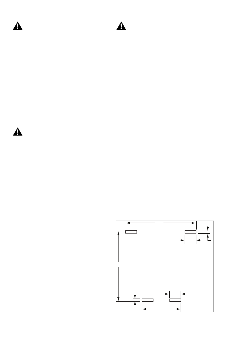
Mount Module
Select a location close enough to the burner to allow a
short (3 ft. [0.9 m] maximum), direct cable route to the
igniter. Ambient temperature at the module must be within
the range listed under Specifications. The module must
be protected from water, moisture, corrosive chemicals
and excessive dust and grease. Refer to Fig. 2 and 3 for
recommended slot/hole pattern in appliance.
99.5
16
100
4
16
4
69-2076—01 4
55
Fig. 2. Recommended slot/hole pattern in appliance
(in mm).
M24198
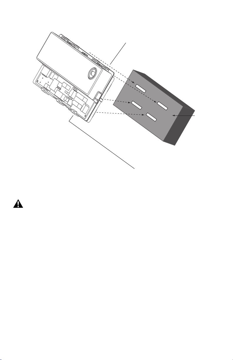
S9360A, S9361A, S9370A, S9371A INTEGRATED BOILER CONTROLLERS
WATER
HEATER
M24229
Fig. 3. Align module with slots in control box.
CONTROL
BOX
Wire the System
WARNING
Electrical Shock Hazard.
Can cause severe injury, death or property
damage.
Disconnect the power supply before making wiring
connections to prevent electrical shock or
equipment damage.
Check the wiring diagram furnished by the appliance
manufacturer for circuits differing from the wiring hookup
shown in Fig. 4 and 5. Carefully follow any special
instructions affecting the general procedures outlined
below.
IMPORTANT
1. All wiring must comply with applicable local
electrical codes and ordinances.
2. When installing a hot surface igniter, the
leadwires should be kept as short as possible
and should not be allowed to rest against
grounded metal surfaces.
3. A common ground is required for the S93XX and
the main burner. The 24V “secondary” plug internally grounds one side of the transformer. Any
auxiliary controls or limits must not be in the
grounded leg. In addition, the appliance should
be earth-grounded.
4. Make sure the transformer has adequate VA.
The ignition module requires at least 0.2A at 24
Vac. Add the current draws of all other devices in
the control circuit, including the gas control, and
multiply by 24 to determine the total VA
requirements of these components. Add this
total to 5.0 VA (for the module). The result is the
minimum transformer VA rating. Use a Class II
transformer if replacement is required.
5. Check that L1 (hot) and L2 (neutral) are wired to
the proper terminals.
Connect Ignition Cable (S936XAXXXX)
Use Honeywell ignition cable or construct an ignition
cable that conforms to suitable national standards, such
as Underwriters Laboratories Inc. See Specifications
section. To construct a cable, fit one end (the module end)
with 1/4 in. connector receptacle and the other with a
connector to match the pilot assembly. Protect both ends
with insulated boots.
5 69-2076—01
 Loading...