


RTH7400D
Programmable Thermostat
OWNER’S GUIDE
The RTH7400D Thermostat provides electronic control of 24 Vac heating and cooling systems or 750 mV heating systems.
For assistance with your Honeywell product, please visit www.honeywell.com/yourhome or call Honeywell Customer Care toll free at 1-800-468-1502.
Read and Save these Instructions
Patents Pending |
|
® U.S. Registered Trademark |
|
© 2004 Honeywell International Inc. |
69-1726-1 |
All Rights Reserved |

Contents
Prepare for Installation ............................................................ |
3 |
Follow Important Instructions .................................................. |
5 |
Remove Old Thermostat ......................................................... |
6 |
Follow Special Instructions...................................................... |
7 |
Label Old Thermostat Wires ................................................... |
10 |
Mount New Wallplate to Wall .................................................. |
11 |
Connect Wires to New Wallplate............................................. |
15 |
Install Batteries........................................................................ |
23 |
Attach New Thermostat to Wallplate ....................................... |
24 |
Configure Installer Setup......................................................... |
26 |
Customer Assistance .............................................................. |
62 |
Limited One-Year Warranty..................................................... |
63 |
69-1726—1 |
2 |

Step 1. Prepare for Installation
1.Check that the following items are included:
WALLPLATE
THERMOSTAT
MOUNTING SCREWS (2)
AND WALL ANCHORS (2)
OWNER'S GUIDE
WIRE LABELS
CAUTION CARD
OWNER'S GUIDE
 CAUTION
TURN OFF POWER to system at the furnace, or at the fuse/circuit breaker panel before you begin.
Match the letter of your old thermostat wire with the terminal of the corresponding letter on your new thermostat or base.
|
|
|
|
|
|
|
Ó |
N |
|
|
|
|
|
|
Mon |
|
|
|
|
fusibles-interruptor té |
|
|
|
|
|
|
|
|
|
|
|
|
|
B |
B |
Y2 |
C |
E |
F |
F |
|
|
|
|
|
|
|||||||||
|
|
|
|
|
|
G |
G H |
H |
L |
O |
P |
P |
|
|
|
|
|
|
|
R |
R |
RC |
RH |
T |
U |
U |
|
V/VR V/VR |
W |
W1 |
W2 |
W3 |
W3 |
Read and save these instructions
X |
X2 |
Y1 |
Y1 |
ell.com/yourhome |
M22278


 If any of the items shown above are missing, call


 Honeywell Customer Care at 1-800-468-1502


 before returning the thermostat to the store.
3 |
69-1726—1 |

Step 1. Prepare for Installation (Cont)
2.Check that you have everything required for the installation:
•Two AA alkaline batteries
•No. 2 Phillips screwdriver and standard pocket screwdriver
•Drill
•Drill bit—use 3/16 in. for drywall; use 7/32 in. for plaster
•Level (optional)
•Hammer
•Pencil
•Electrical tape
69-1726—1 |
4 |
Step 2. Follow Important Instructions
1.Do not connect the wires to the new thermostat based on wire color because damage can occur to the heating and/or cooling system.
These Installation Instructions explain later how to use the enclosed wire labels to correctly mark the wires connected to your old thermostat.
OLD THERMOSTAT
|
YELLOW |
|
|
WHITE |
! |
Y |
W |
|
|
RED |
DO NOT WIRE |
|
|
NEW THERMOSTAT |
G |
|
BASED ON |
GREEN |
|
WIRE COLOR. |
|
R |
|
RC |
ORANGE |
|
|
|
M22034 |
5 |
69-1726—1 |
Step 3. Remove Old Thermostat
1.Turn off power at the heating and/or cooling system or fuse/circuit breaker panel.
2.Remove the cover from the old thermostat.
3.Remove the old thermostat from the wall or wallplate. Do not remove the wires.
|
OLD THERMOSTAT |
|
WALLPLATE |
Y |
W |
|
THERMOSTAT |
G |
|
R |
COVER |
C |
|
. |
|
.2 18 |
|
L |
|
O |
|
.25 |
NGER |
|
.3 |
.9 .7 .5
.4
M22036
 MERCURY NOTICE
If you are replacing a thermostat that contains mercury in a sealed tube, do not place your old thermostat in the trash.
Contact your local waste management authority for instructions regarding recycling and the proper disposal of an old thermostat containing mercury in a sealed tube.
69-1726—1 |
6 |
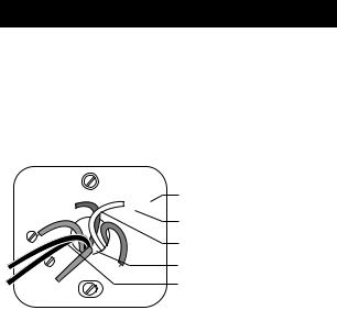
Step 4. Follow Special Instructions
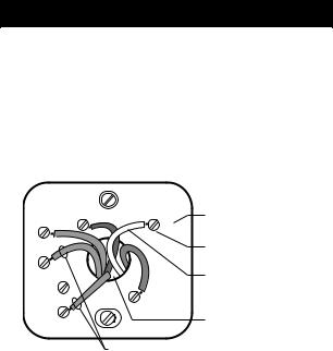
1.If you have two C and/or C1 wires connected to your old thermostat, do not connect them to your new thermostat.
2.Disconnect the C and/or C1 wires. Make sure they do not touch each other or any other wires.
3.Wrap the bare end of each C and/or C1 wire with electrical tape.
OLD THERMOSTAT
Y |
W |
LETTER |
DESIGNATION |
||
G |
|
SCREW |
|
|
TERMINAL |
C |
|
WIRE |
|
R |
|
C |
|
WIRE HOLE |
|
|
DO NOT CONNECT TO NEW
THERMOSTAT
M22201
7 |
69-1726—1 |
Step 4. Follow Special Instructions (Cont)
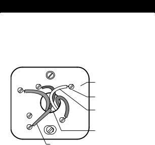
4.If you have only one C and/or C1 wire connected to your old thermostat, connect this wire to C on the new thermostat.
OLD THERMOSTAT
Y |
W |
LETTER |
DESIGNATION |
||
G |
|
SCREW |
|
|
TERMINAL |
|
|
WIRE |
|
R |
|
C |
|
WIRE HOLE |
|
|
CONNECT TO THE "C" ON THE
NEW THERMOSTAT
M22223
69-1726—1 |
8 |
Step 4. Follow Special Instructions (Cont)
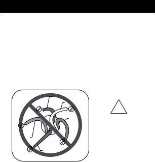
5.If you find any wires not connected to your old thermostat, do not connect them to your new thermostat.
6.Wrap the end of the wires that are not connected with electrical tape.
OLD THERMOSTAT
Y

 W
W
G
 R
R
RC
LETTER DESIGNATION
SCREW TERMINAL
WIRE
WIRE HOLE
WIRES NOT CONNECTED – DO NOT CONNECT TO
NEW THERMOSTAT
M22040
9 |
69-1726—1 |
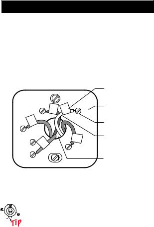
Step 5. Label Old Thermostat Wires
1.As you disconnect each wire, use the enclosed wire labels to wrap a wire label around each wire that matches the letter designation. Do not allow the wires to fall into the wall opening after the wires are disconnected.
2.Remove any remaining part of the old thermostat from the wall.
OLD THERMOSTAT
Y |
Y |
W |
W |
|
|
||
G |
|
|
|
G |
|
|
R |
RC |
|
|
|
|
|
|
|
|
|
|
R |
RC |
|
|
|
WIRE LABEL
LETTER DESIGNATION
SCREW
TERMINAL
WIRE
WIRE HOLE
M22039
When connecting the wires to the new thermostat, refer to the wire labels. Do not connect wires to your new thermostat based on the color of the wire.
69-1726—1 |
10 |
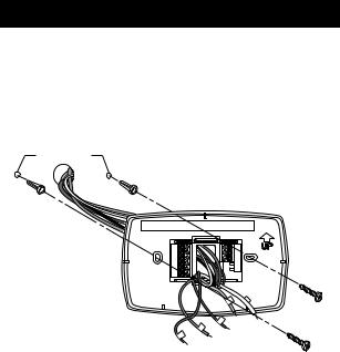
Step 6. Mount New Wallplate to Wall
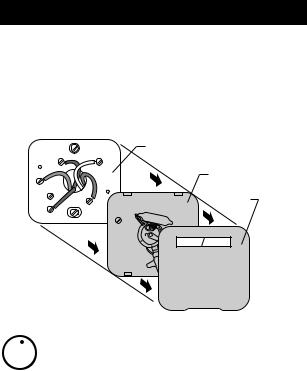
1.Separate the wallplate from the thermostat as shown.
WALLPLATE
WIRE HOLE
THERMOSTAT
M22267
11 |
69-1726—1 |
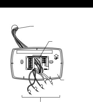
Step 6. Mount New Wallplate to Wall (Cont)
2.Pass the labeled wires through the wire hole on the wallplate.
WALL OPENING
WIRE HOLE
WALLPLATE
LABELED WIRES |
M22279 |
69-1726—1 |
12 |
Step 6. Mount New Wallplate to Wall (Cont)
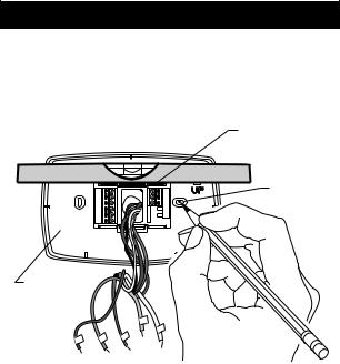
3.Position the wallplate on the wall with the arrow pointing up. Level the wallplate (for appearance only) and mark the two mounting holes with
a pencil.
PLACE LEVEL ON
SUPPORT TABS
LEVEL
MARK
MOUNTING
HOLES (2)
WALLPLATE
M22292
13 |
69-1726—1 |
Step 6. Mount New Wallplate to Wall (Cont)
4.Move the wallplate aside and drill holes at the locations marked on the wall. Drill 3/16 in. holes for drywall or 7/32 in. holes for plaster.
5.Tap the wall anchors into the drilled holes until even with the wall surface.
DRILLED
HOLES (2)
WALL
ANCHORS (2)
WALLPLATE
|
MOUNTING |
M22293 |
SCREWS (2) |
6.Position the wallplate over the wall anchors.
7.Insert the mounting screws into the wall anchors. Check leveling, if desired, and tighten the mounting screws.
69-1726—1 |
14 |
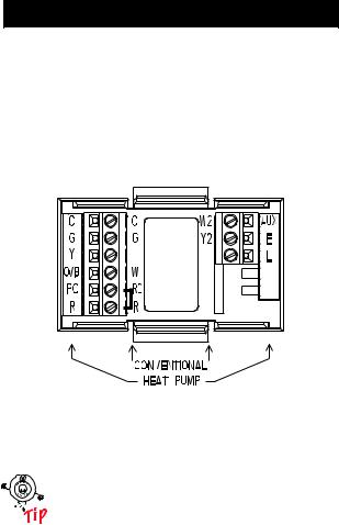
Step 7. Connect Wires to New Wallplate
1.Match the labeled wires to the letter designations on the wallplate.
2.Select the correct letter designations to follow for your system. If you have a standard heating and/or cooling system, use the CONVENTIONAL letter designations. If you have a heat pump system, use the HEAT PUMP letter designations to wire the new thermostat.
M22294
See table on page 30 to help you determine if you have a CONVENTIONAL or HEAT PUMP system.
15 |
69-1726—1 |
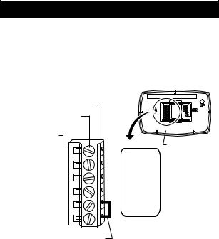
Step 7. Connect Wires to New Wallplate (Cont)
3.If wires are to be connected to both Rc and R, loosen the Rc and R screw terminals and remove the metal jumper wire.
4.If only one of the terminals, Rc or R, is to be connected, leave the metal jumper wire in place.
TERMINAL BLOCK
SCREW TERMINALS
LETTER DESIGNATIONS
WALLPLATE
C
G
Y
O/B
RC
R
METAL JUMPER WIRE |
M22295 |
69-1726—1 |
16 |
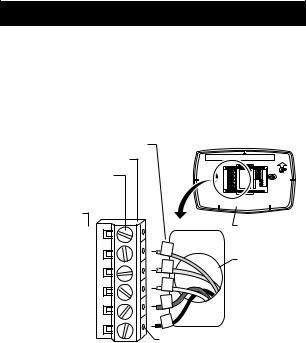
Step 7. Connect Wires to New Wallplate (Cont)
5.Loosen the screw terminals. Insert the labeled wires into the holes on the side of the terminal block that match the letter designations. Tighten the screw terminals.
6.If any of the labeled wires do not match the letter designations, see next page for wire connections.
LABELED WIRES
TERMINAL BLOCK
SCREW TERMINALS
CONVENTIONAL LETTER DESIGNATIONS
WALLPLATE
C |
|
|
G |
G |
|
WIRE HOLE |
||
|
||
Y |
Y |
|
|
||
W |
W |
|
C |
||
|
||
|
R |
|
RC |
|
|
|
R |
|
R |
|
|
|
INSERT WIRE IN HOLE |
|
|
M22325 |
17 |
69-1726—1 |
Step 7. Connect Wires to New Wallplate (Cont)
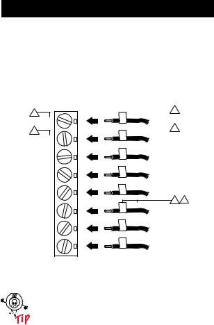
7.Compare letter designations on your old and new thermostats. Use the information below if you are wiring a CONVENTIONAL System. Use the information on page 20 if you are wiring a Heat Pump system.
CONVENTIONAL |
|
Possible letter |
letter designations |
|
designations on |
on the new thermostat |
|
the labeled wires |
1
RC
1
R
W
Y
G
C
Y2
W2
 RC
RC
 R
R
 W
W
 Y
Y
 G
G
 C
C
 Y2
Y2
 W2
W2
 2 or R
 2 or RH, 4, V
or W1, H
or Y1, M
or F
3 4
or C1, X, B
M22208
Do not connect more than one wire to each terminal. Be sure to read the notes referenced in the numbered triangles above. These numbered notes appear on the next page.
69-1726—1 |
18 |

Step 7. Connect Wires to New Wallplate (Cont)
NOTES FOR CONVENTIONAL HEATING AND COOLING SYSTEMS
1If wires will be connected to both RC and R on the new thermostat, remove metal jumper wire between RC and R. Leave metal jumper wire in place if only one of the terminals, RC or R, will be connected on the new thermostat.
2If wires were connected to both R and RH terminals on the old thermostat, remove metal jumper wire between RC and R on the new thermostat. Connect the old R to the new RC and the old RH to the new R.
3If two C and/or C1 wires were connected to the old thermostat, do not connect them to the new thermostat. Wrap the bare end of each wire separately with electrical tape and do not use.
4If one C and/or C1 wire was connected to the old thermostat, the wire should be connected to the "C" letter designation on the new thermostat.
M22246
19 |
69-1726—1 |
Step 7. Connect Wires to New Wallplate (Cont)
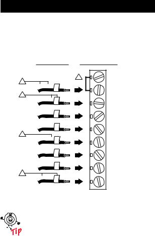
8.Compare letter designations on your old and new thermostats. Use the information below if you are wiring a HEAT PUMP system.
Possible letter |
|
HEAT PUMP letter |
|
designations on |
designations on the |
||
the labeled wires |
|
new thermostat |
|
2 |
|
1 |
RC |
|
|
|
|
VR or V or |
R |
|
|
|
|
|
R |
3 |
|
|
|
H or B, |
O |
|
|
|
|
|
O/B |
Y1 or M or |
Y |
|
Y |
|
|
|
|
F or |
G |
|
G |
|
|
|
|
3 |
|
|
|
X or B, |
C |
|
C |
|
|
|
|
F or |
L |
|
L |
|
|
|
|
X2 or X, |
E |
|
E |
|
|
|
|
4 |
|
|
|
AUX, W1, W or W2 |
|
|
|
|
|
|
AUX |
M22210
Be sure to read the note referenced in the numbered triangles above. These numbered notes appear on the next page.
69-1726—1 |
20 |
 Loading...