


Q7230A
Table of contents
 Loading...
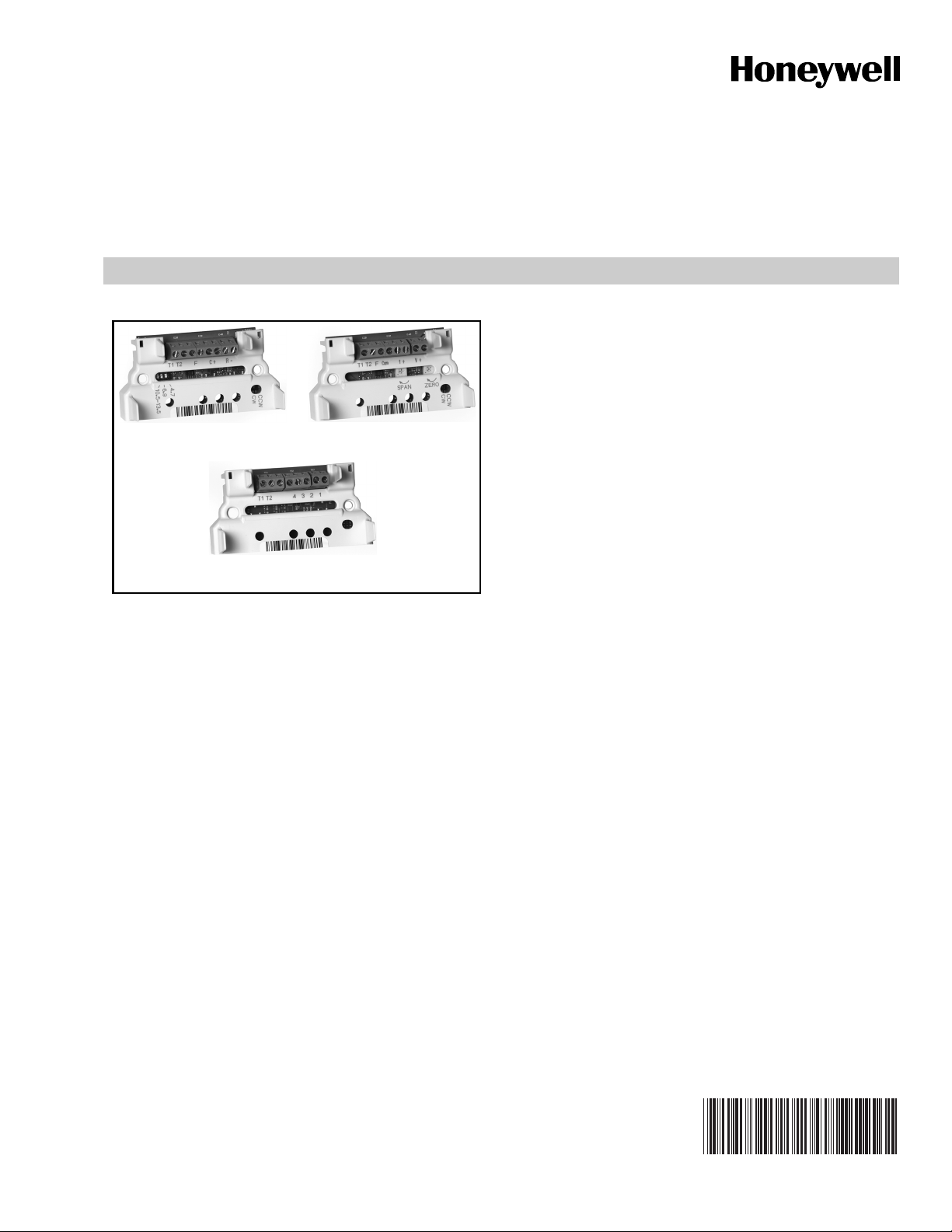
Q7130A, Q7230A, Q7330A
Q7130A Q7230A
Q7330A
Modutrol IV Interface Modules
FEATURES
• Mounts inside the wiring box of any Series 90 Modutrol
IV Motor (M91XX models). Module protected from
weather by the Modutrol IV NEMA 3 wiring box.
• Mates to quick-connect terminals in motor wiring box
and provides screw terminals for control wiring
connections.
• Features solid state circuitry with surface mount
components.
• Plastic enclosure provides easy handling and
protection for circuitry.
• Q7130A provides selectable voltage range (4-7, 6-9, or
10.5-13.5 Vdc). Adapts M91XX Modtrol IV Motor to
function as M71XX model for M734H,J, M744D,
M745G,P replacements. Includes reversing switch to
allow replacement of electrically normally open or
electrically normally closed motors.
APPLICATION
The Q7130, Q7230, and Q7330 Modutrol IV Interface
Modules are used with Series 90 Modutrol IV Motors (M91XX)
for conversion to electronic (Series 70) control.
• Q7230A provides current or voltage control (4-20 mA
and 2-10 Vdc) with adjustable zero and span. Adapts
the M91XX Modutrol IV Motor to function as M72XX
model for M744S,T,Y or M745S,T,Y replacements.
Includes reversing switch to allow replacement of
electrically normally open or electrically normally
closed motors.
• Q7330A is an interface to W936 and W945 controls.
Adapts the M91XX Modutrol IV Motor to function as
M73XX model for M734D, M744A, M745A replacements.
INSTALLATION INSTRUCTIONS
63-2235-05
Q7130A, Q7230A, Q7330A MODUTROL IV INTERFACE MODULES
SPECIFICATIONS
IMPORTANT:
The specifications given in this publication do not
include normal manufacturing tolerances. Therefore,
this unit may not exactly match the listed specifications. Also, this product is tested and calibrated
under closely controlled conditions and some minor
differences in performance can be expected if those
conditions are changed.
Models:
Q7130A Modutrol IV Interface Module:
Used with M91XX Modutrol IV Motor to replace M71XX
Motor applications. Module controls only one motor.
See Table 1.
Q7230A Modutrol IV Interface Module:
Used with M91XX Modutrol IV Motor to replace M72XX
Motor applications. Module controls only one motor.
See Table 1.
Q7330A Modutrol IV Interface Module:
Used with M91XX Modutrol IV Motor to replace M73XX
Motor applications. Module controls only one motor.
See Table 1.
Electrical Ratings:
Input Voltage: 24 Vac, 50/60 Hz.
Power Consumption: 2 VA.
Input Impedance:
Q7130A: >100k ohms.
Q7230A: voltage input >100k ohms; current input 67 ohms.
Temperature Rating: -40° F to +150° F [-40° C to + 66° C].
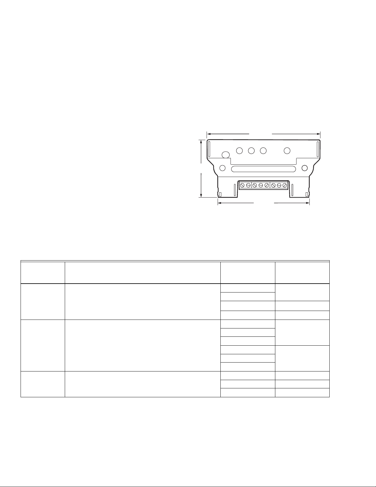
Dimensions: See Fig. 1.
3-25/32 (96)
1-59/64
(49)
3-5/64 (78)
M27211
Fig. 1. Q7130,Q7230,Q7330 Modutrol IV Interface Module
dimensions in in. (mm).
Table 1. Interface Module Function/Application Chart.
And Replaces
This Model Provides Interface For
These Old Style
a
Motors
When Used with
Series 90 Models:
Q7130A Selectable voltage ranges: 4-7, 6-9, or 10.5 to 13.5 Vdc M734H M9164D1009
M734J
M744D
b
M9184D1021
M745G M9185A1018
Q7230A Adjustable zero and span, voltage or current M9184D1021
control (includes 4-20 mA and 2-10 Vdc).
M744S M9184D1021
M744T
M744Y
M745S M9185D1004
M745T
M745Y
Q7330A W936 or W945 control interface. M734D M9164D1009
M744A M9184D1021
M745A M9185D1004
a
Refer to customer.honeywell.com for cross-reference details.
b
M744D1037 and M744D1045 do not apply.
63-2235—05 2
Q7130A, Q7230A, Q7330A MODUTROL IV INTERFACE MODULES
CAUTION
CAUTION
INSTALLATION
When Installing This Product…
1. Read these instructions carefully. Failure to follow them
could damage the product or cause a hazardous condition.
2. Check the ratings and description given in this specification to make sure the product is suitable for your
application.
3. Installer must be a trained, experienced service technician.
4. After installation is complete, check out product operation as provided in these instructions.
Disconnect power before installation to prevent
electrical shock or equipment damage.
IMPORTANT:
For ease of adjustment, make all stroke and auxiliary
switch adjustments before installing the interface
module. After installation, access to the stroke adjust
cams and auxiliary switches inside the motor is
restricted. For complete details on performing these
adjustments, refer to the specification sheet packed
with the Modutrol Motor.
SETTINGS AND ADJUSTMENTS
Module Adjustments
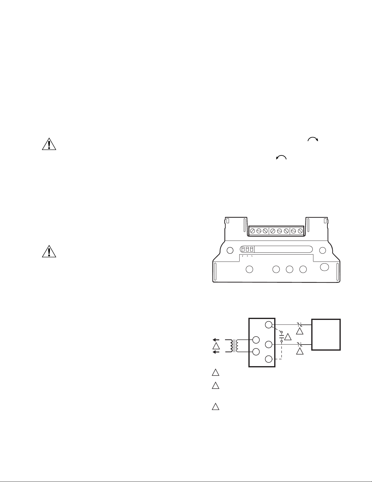
Q7130A Adjustments (Fig. 2)
The Q7130A provides selectable range, two-wire voltage
control (4-7, 6-9 or 10.5-13.5 Vdc). It includes a clockwise/
counterclockwise (cw/ccw) switch for replacing electrically
normally open or electrically normally closed motors. Remove
film on switch before use.
1. Select desired voltage range using the three-position
switch.
2. Select desired rotation. Select cw for electrically normally closed (motor drives clockwise , as viewed
from power end, to open with an increase in control signal). Select ccw for electrically normally open (motor
drives counterclockwise , as viewed from power
end, to close with an increase in control signal).
3. See Fig. 3 for typical system wiring.
4. Set controller to drive motor to fully open position and
then to fully closed position to check for proper operation. (See Table 2.)
Installing Terminal Block
When installing the terminal block on the motor
quick connects, push the board straight down.
Rocking or tilting of the board can damage the
electrical connectors and result in an inoperative
wiring module.
1. Disconnect power from the M91XX Modutrol IV Motor to
prevent electrical shock or equipment damage.
2. Remove wiring box cover from the motor by removing
four screws.
3. Disconnect all field wiring from the motor.
4. If motor has an internal transformer, make sure trans-
former is not powered and disconnect secondary wires
from T1 and T2 terminals. Clip quick-connect terminations from transformer secondary (brown) wires. Trim
1/8 to 1/4 in. (3 to 6 mm) of insulation from the ends of
the wire. Tin wire ends with solder.
5. Plug terminal block onto quick-connect terminals inside
wiring box.
6. Connect field wiring to screw terminals on terminal
block. See Fig. 2, 4, and 8 for terminal designations.
Trim wire ends neatly and tin with solder.
7. Position circuit module and secure.
T1
10.5-13.5
6.9
4.7
F
T2
C+
A–
Fig. 2. Q7130A terminals and adjustments.
MOTOR
+
3
3
MODULATING
DC VOLTAGE
SOURCE
–
C
2
24V
T1
R
T2
F
L1
(HOT)
1
L2
TRANSFORMER
1
POWER SUPPLY. ADD DISCONNECT MEANS AND OVERLOAD
PROTECTION AS REQUIRED.
2
OPTIONAL NORMALLY OPEN SWITCH. WITH CCW SELECTION,
MOTOR WILL RUN TO FULLY CLOSED; WITH CW SELECTION
MOTOR WILL RUN TO FULLY OPEN WHEN THIS SWITCH CLOSES
(AS LONG AS POWER IS APPLIED TO T1, T2 TERMINALS).
3
OPTIONAL NORMALLY CLOSED SWITCHES. FINE SILVER OR
DRY CONTACTS REQUIRED. WITH CCW SELECTION, MOTOR
WILL RUN TO FULLY OPEN; WITH CW SELECTION, MOTOR WILL
RUN TO FULLY CLOSED WHEN SWITCH IN EITHER C OR R
LEAD IS OPENED.
CW
CCW
M27212
M505C
Fig. 3. Typical system wiring for Q7130A Interface Module
and M91XX Modutrol Motor.
3 63-2235—05
Loading...