


 Loading...
L404F,T,V
PressureTrol® Controllers
PRODUCT DATA
FEATURES
APPLICATION
L404F PressureTrol® Controllers provide operating control with automatic limit protection for pressure systems of up to 2070 kPa, or 300 psi.
L404T,V PressureTrol® Controllers are for use on oil burner systems for pressures up to 1035 kPa or 150 psi.
•Models available in a series of control ranges, and pressure scales in kPa and psi.
•All models automatically reset and have an adjustable differential.
•Models have snap switch to open or close a circuit on a pressure rise.
•Case has a clear plastic cover so setpoints can be observed.
•1/4 inch—18 NPT connection for pipe on diaphragm assembly.
•Ground screw terminal.
L404F:
•Controllers may be used with steam, air, or noncombustible gases, or fluids noncorrosive to the pressure sensing element.
L404T:
•High pressure limits, break a circuit on oil pressure rise above setpoint.
L404V:
•Low pressure limits, makes a circuit on oil pressure rise above setpoint.
|
Contents |
Application ........................................................................ |
1 |
Features ........................................................................... |
1 |
Specifications ................................................................... |
2 |
Ordering Information ........................................................ |
2 |
Installation ........................................................................ |
4 |
Settings and Adjustments ................................................. |
6 |
Checkout .......................................................................... |
7 |
71-2429-06
L404F,T,V PRESSURETROL® CONTROLLERS
SPECIFICATIONS
Model:
L404F,T,V PressureTrol® Controllers. See Table 1.
Table 1. Models with kPa—psi and Other Pressure Scales.
|
|
|
Subtractive Differentiala |
Maximum Diaphragm |
||||
|
Operating Ranges |
|
pressure |
|||||
Model Number |
kPa |
psi |
kPa |
|
psi |
kPa |
|
psi |
L404F1060 |
15 to 100 |
2 to 15 |
15 to 40 |
2 to |
6 |
170 |
|
25 |
L404F1078 |
35 to 350 |
5 to 50 |
40 to 100 |
6 to |
14 |
590 |
|
85 |
L404F1094 |
140 to 2070 |
20 to 300 |
140 to 345 |
20 to 50 |
2410 |
|
350b |
|
L404F1102 |
70 to 1035 |
10 to 150 |
70 to 150 |
10 to 22 |
1550 |
|
225 |
|
L404F1219c |
15 to 100 |
2 to 15 |
15 to 40 |
2 to |
6 |
170 |
|
25 |
L404F1243c |
35 to 350 |
5 to 50 |
40 to 100 |
6 to |
14 |
590 |
|
85 |
L404F1227c |
70 to 1035 |
10 to 150 |
70 to 150 |
10 to 22 |
1550 |
|
225 |
|
L404F1235c |
140 to 2070 |
20 to 300 |
140 to 345 |
20 to 50 |
2410 |
|
350b |
|
L404F1300c |
415 to 1240 |
60 to 180 |
40 fixed |
6.0 Fixed |
1550 |
|
225 |
|
L404F1326 |
0 to 100 |
0 to 15 |
15 to 40 |
2 to |
6 |
170 |
|
25 |
L404F1334 |
0 to 350 |
0 to 50 |
40 to 100 |
6 to |
14 |
590 |
|
85 |
L404F1342 |
35 to 1000 |
5 to 145 |
70 to 150 |
10 to 22 |
1550 |
|
225 |
|
L404F1359 |
70 to 2000 |
10 to 290 |
140 to 345 |
20 to 50 |
2410 |
|
350b |
|
L404F1367 |
7 to 55 |
1 to 8 |
5 to 14 |
0.75 to 2 |
170 |
|
25 |
|
|
|
|
|
|
|
|
|
|
L404F1375d |
35 to 350 |
5 to 50 |
40 to 100 |
6 to |
14 |
590 |
|
85 |
L404F1383d |
70 to 1035 |
10 to 150 |
70 to 150 |
10 to 22 |
1550 |
|
225 |
|
L404F1391d |
140 to 2070 |
20 to 300 |
140 to 345 |
20 to 50 |
2410 |
|
350b |
|
L404F1409d |
15 to 100 |
2 to 15 |
15 to 40 |
2 to |
6 |
170 |
|
25 |
L404F1441 |
0.35 to 3.5 Kg/cm2 |
5 to 50 psi |
0.4 to 1.0 Kg/cm2 |
6 to |
14 psi |
6 Kg/cm2 |
|
85 psi |
L404T1055 |
35 to 350 |
5 to 50 |
40 to 100 |
6 to |
14 |
590 |
|
85 |
|
|
|
|
|
|
|
|
|
L404T1063 |
70 to 1035 |
10 to 150 |
70 to 150 |
10 to 22 |
1550 |
|
225 |
|
|
|
|
|
|
|
|
|
|
L404V1087d |
70 to 1035 |
10 to 150 |
70 to 150 |
10 to 22 |
1550 |
|
225 |
|
L404V1095d |
35 to 350 |
5 to 50 |
40 to 100 |
6 to |
14 |
590 |
|
85 |
aNominal at midscale operating range.
bBrass bellows instead of stainless steel diaphragm.
cModels with 1/4-19 BSPT thread instead of 1/4-18 NPT thread.
dMake-on-rise models with terminal B omitted for miswiring compliance.
ORDERING INFORMATION
When purchasing replacement and modernization products from your TRADELINE® wholesaler or distributor, refer to the TRADELINE® Catalog or price sheets for complete ordering number.
If you have additional questions, need further information, or would like to comment on our products or services, please write or phone:
1.Your local Honeywell Automation and Control Products Sales Office (check white pages of your phone directory).
2.Honeywell Customer Care 1885 Douglas Drive North
Minneapolis, Minnesota 55422-4386
In Canada—Honeywell Limited/Honeywell Limitée, 35 Dynamic Drive, Toronto, Ontario M1V 4Z9.
International Sales and Service Offices in all principal cities of the world. Manufacturing in Australia, Canada, Finland, France, Germany, Japan, Mexico, Netherlands, Spain, Taiwan, United Kingdom, U.S.A.
71-2429—06 |
2 |
L404F,T,V PRESSURETROL® CONTROLLERS
Table 2. Conversion Table.
|
Operating Range Conversions |
Subtractive Differential Conversions |
||||
kg/cm2 |
|
kPa |
psi |
kg/cm2 |
kPa |
psi |
0.1 to 1.05 |
|
15 to 100 |
2 to 15 |
0.15 to 0.4 |
15 to 40 |
2 to 6 |
|
|
|
|
|
|
|
0.4 to 3.5 |
|
35 to 350 |
5 to 50 |
0.4 to 1.0 |
40 to 100 |
6 to 14 |
|
|
|
|
|
|
|
0.7 to 10.0 |
|
70 to 1035 |
10 to 150 |
0.7 to 1.6 |
70 to 150 |
10 to 22 |
|
|
|
|
|
|
|
1.5 to 20.0 |
|
140 to 2070 |
20 to 300 |
1.5 to 3.5 |
150 to 300 |
20 to 50 |
|
|
|
|
|
|
|
Table 3. Switch Ratings (Amperes).
Switch State |
120 Vac |
240 Vac |
Full Load |
8.0 |
5.1 |
Locked Rotor |
48.0 |
30.6 |
Pressure Sensing Element: Stainless steel diaphragm (140 to 2070 kPa models) has brass bellows.
Maximum Ambient Temperature: 66°C (150°F). Also, refer to note under Mounting.
Adjustment Means: Screws on top of control case. Scales are marked in psi or kPa.
Mounting Means: 1/4 inch-18 NPT connection on diaphragm assembly; or surface mounts using holes in back of case.
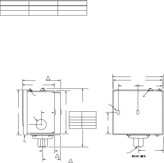
Dimensions: See Fig. 1.
Switching Action: Snap switch breaks R-B (closes R-W) on pressure rise. Make-on-rise devices omit terminal B.
Grounding Means: Ground screw terminal marked with a circled ground symbol.
Accessories:
50024585-001 Brass Steam Trap. (Please refer to the applicable Equipment/Application Standards for compliance.)
14026 Steel Steam Trap. (Please refer to the applicable Equipment/Application Standards for compliance.)
118023 Steel Steam Trap for BSPT Models.
33312B Knurled Knob—fits on top of adjusting screws. 4074BWJ Range Stop—range stop screw, Part No. 107194,
and wrench, Part No. 23466, to limit setpoint range.
Approvals:
Underwriters Laboratories Inc. Listed: file no. MP466, vol. 10, guide no. MBPR.
Canadian Standard Association certified: file no. LR1620, guide no. 400E-0.
|
|
|
|
|
4-1/2 (115) |
|
|
|
1 |
|
|
4-11/32 (111) |
|
|
3-1/4 (83) |
|
|
|||
|
2-3/4 (70) |
|
|
1-61/64 (50) |
1-15/16 (49) |
|
|
|
|
|
|
||
|
DIFFERENIAL |
|
|
|
MAIN SCALE |
|
|
ADJUSTMENT |
|
|
|
||
|
|
|
|
ADJUSTMENT |
||
|
|
SCREW |
|
|
3/16 X 11/32 |
|
|
|
|
|
SCREW |
||
|
|
|
|
|
(5 X 9) |
|
|
|
|
DIMENSION |
|
||
|
|
|
KNOCKOUT |
|
||
|
|
3-3/4 |
|
"A" |
|
|
|
|
|
|
|
||
3-7/8 |
HOLE FOR |
(95) |
(SEE TAB) |
|
|
|
(99) |
|
|
|
|
|
|
1/2 INCH |
1-3/16 |
PSI |
DIMENSION |
|
|
|
|
|
|
||||
|
CONDUIT |
(30) |
|
|
||
|
RANGE |
"A" |
|
|
||
|
|
|
|
|
||
|
|
|
2 TO 15 |
123 |
|
|
|
|
|
5 TO 50 |
126 |
1-13/16 |
|
|
|
|
|
|
|
|
|
|
|
10 TO 150 |
126 |
(46) |
|
|
|
|
20 TO 300 |
146 |
|
|
|
13/16 (21) |
|
|
|
|
|
|
CLEAR |
|
|
|
|
|
|
PLASTIC |
|
|
|
|
|
|
COVER |
|
|
|
|
|
|
|
1-1/16 (27) |
|
|
|
2-1/8 (54) |
|
|
|
|
1/4 –18 NPT |
|
|
|
|
|
|
|
|
|
|
|
1 |
|
|
|
|
|
|
1-1/2 (38) |
|
|
|
|
|
|
|
1 15 TO 100 kPa (2 TO 15 PSI) SCALE MODELS ONLY. |
M19635B |
||
|
|
|
|
|
|
|
Fig. 1. L404F,T,V approximate dimensions in inches (millimeters in parentheses).
3 |
71-2429—06 |
Loading...